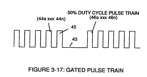
Figure (3-17)
Gated Pulse Train
How it is written
- (3-17) 2×
Drawings 2
-
Captioned as this figure · Gated Pulse Frequency generator (80)
-
Captioned as this figure · WFC 422DA - Illustrations
On this figure 5
- 42 Clock Signal
- 45 Non-Combustible Gases
- 46 Ionized Ambient Air Gases
- 71 Magnetic Field Coupling
- T2 Duty Cycle of Pulse Train
Where it is named · 2
Gated Pulse Frequency generator (80) 1×
-
Gated Pulse Circuit (80) of Figure (3-5) switches "off' and "on" sections of incoming clock signal (42) to form gated pulse (45) which is, in turn, duplicated in succession to produce gated pulse train (46a xxx 46n) of Figure (3-17).
Water Fuel Injector 1×
-
As incoming gated pulse-train (46a xxx 46n) of Figure (3-17) is electronically "tuned" to adjust pulse off- time (T2) to compensate for "rise" and "fall" of magnetic field coupling (71a xxx 71n) for a predetermined resonant pulse-frequency established and determined by the dielectric value of natural water in direct relationship to resonant cavity geometrical configuration