(19)
Pulse-Train Signal
Also written digital signal · input signal · signal
Where it is first named
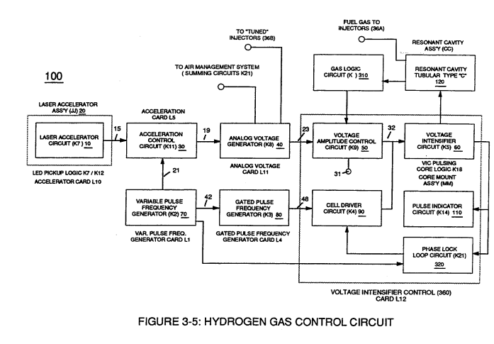
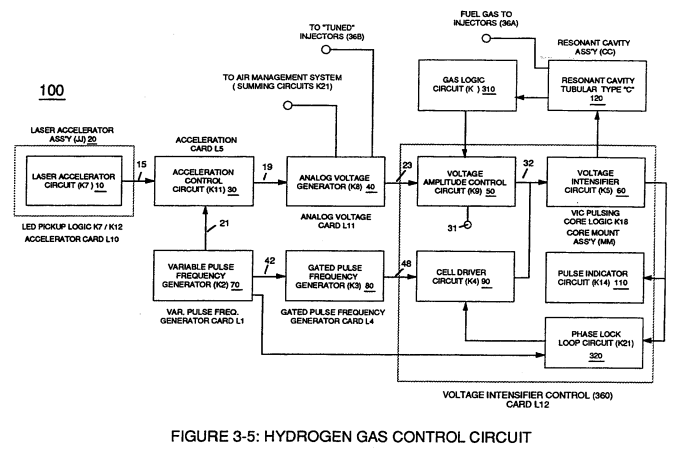
Finally, circuit (30) reproduces the variable controlled pulse-shape (16) in a continuous repetitive manner (16a xxx 16n) of Figure (3-13) and electrically transmits the resultant pulse-train signal (19) to Analog Voltage Circuit (40), as shown in Figure (3-5).
How it is written
- (19) 5×
Drawings 30
-
Stanley A. Meyer Page.13 of 28° · WFC 417 — WFC 417
-
I, is the forward current through LED cluster-Array; Vo¢ is volts applied (typically 5 volts). Stanley A. Meyer Page 14 of 28 · WFC 417 — WFC 417
-
Copyright © 1983 by Stanley A Meyer Stanley A. Meyer Page16 of 28 · WFC 417 — WFC 417
-
Page 20 · WFC 417 — WFC 417
-
Figure (1-19) · Thermal Explosive Energy
-
Figure (3-5) · Acceleration Control Circuit (30)
-
Analog Voltage Circuit (40), as shown in Figure (3-5) · Acceleration Control Circuit (30)
-
Figure (3-5) · Acceleration Control Circuit (30)
-
Figure (3-5) · Analog Voltage generator (40)
-
Figure (3-19) · Cell Driver Circuit (90)
-
Figure (3-19) · Voltage Intensifier Circuit (60)
-
Figure (3-5) · Laser Distributor
-
Carries this number · WFC 422DA - Illustrations
-
Carries this number · WFC 422DA - Illustrations
-
3-4 Inner Core Bobbin · Voltage Intensifier Coil Assembly
-
3-6 Pulsing Core · Voltage Intensifier Coil Assembly
-
Carries this number · Electronic Circuit Design
-
Carries this number · Electronic Circuit Design
-
Carries this number · Electronic Circuit Design
-
Carries this number · Water Fuel Injector (Taper Resonant Cavity Chamber)
-
Carries this number · Water Fuel Injector (Taper Resonant Cavity Chamber)
-
The Following Page 1-7 was not available · Water Fuel Injector (Taper Resonant Cavity Chamber)
-
Carries this number · Steam Resonator Assembly
-
Carries this number · In-Line Circuit Components
-
Carries this number · 8-1 - Propagating "Resonant Action" By Voltage Tickling of State Space
-
Carries this number · Wobbling Effect
-
The figure it sits on · Analog Voltage generator (40)
-
The figure it sits on · WFC 422DA - Illustrations
-
3-5 Outer Core Bobbin · Voltage Intensifier Coil Assembly
-
3-14 WFC Voltage Ignition Wire · Voltage Intensifier Coil Assembly
Where it is named · 5
Acceleration Control Circuit (30) 1×
-
pulse-train signal (19)
Finally, circuit (30) reproduces the variable controlled pulse-shape (16) in a continuous repetitive manner (16a xxx 16n) of Figure (3-13) and electrically transmits the resultant pulse-train signal (19) to Analog Voltage Circuit (40), as shown in Figure (3-5).
Analog Voltage generator (40) 3×
-
digital signal (19)
The generated digital signal (19) being electrically transmitted from accelerated control circuit (30) of Figure (3-5) is, now, electronically detected, translated, and converted into a analog voltage signal (22) which is continuously proportionate to input signal (19) by Analog Voltage Generator Circuit (40) of Figure (3-5).
-
input signal (19)
The generated digital signal (19) being electrically transmitted from accelerated control circuit (30) of Figure (3-5) is, now, electronically detected, translated, and converted into a analog voltage signal (22) which is continuously proportionate to input signal (19) by Analog Voltage Generator Circuit (40) of Figure (3-5).
-
signal (19)
As pulse width (17ax) of signal (19) changes so does analog voltage level output (23) of Figure (3-14).
Water Fuel Injector (Taper Resonant Cavity Chamber) 1×
-
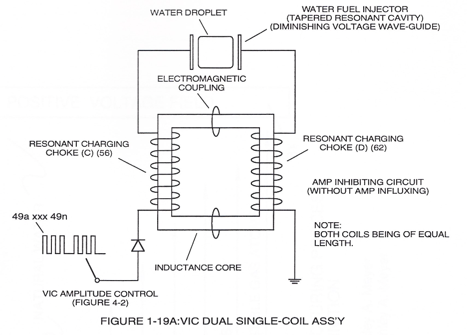
… Together, the resistive valve of Stainless Steel wire-coil (56/57) and its inductance generated electromagnetic field (62) of Figure (19) opposes the movement of electrons since the dielectric valve of wire-coils (56/57) inhibits electron exchange while the generated inductance field (62) locks onto the electromagnetic field of the electrons ...generated coil inductance field (62) being greater in electromagnetic... …