(Z2)
Resonant Choke Coils Electromagnetic Fields Intensity
Also written Resonant Charging Chokes
Where it is first named
Switching Diode (55) of Figure (3-22) prevents Bidirectional electron flow (current flow in one direction only) since Blocking Diode (55) only conducts "current flow" in the direction of schematic-arrow while being placed in-line with VIC Circuit impedance interaction (R1 + Z2 + Z3 + Re), as mathematically extrapolated in Circuit Equation (Eq 9)
How it is written
- (56/Z2 – 62/Z3) 1× with (56) Resonant Charging Choke, (62) Resonant Charging Chokes, (Z3) Resonant Choke Coils Electromagnetic Fields Intensity
- (R1 + Z2 + Z3 + Re) 1× with (R1), (Z3) Resonant Choke Coils Electromagnetic Fields Intensity, (Re) Water
- (Z2) 1×
- (+Z2 / -Z3) 1× with (Z3) Resonant Choke Coils Electromagnetic Fields Intensity
- (Z2 - Z3) 1× with (Z3) Resonant Choke Coils Electromagnetic Fields Intensity
Drawings 28
-
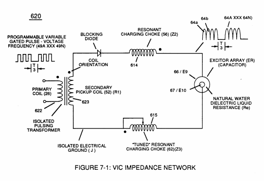
(620) of Figure (7-1) · Instant Explosion of Water
-
(620) of Figure (7-1) · Resistance (Rs)
-
(614) of Figure (7-1) · Inductance (FL)
-
Inductor (614) of Figure (7-1) · Inductance (FL)
-
(614) of (7-1) · Inductance (FL)
-
(750) of Figure (7-14) · Inductance Reactance (Rs - Cd - FL)
-
Carries this number · WFC 426 - Illustrations
-
(620) of Figure (7-1) · 8-6 - VIC Voltage Sync-Pulse Circuit
-
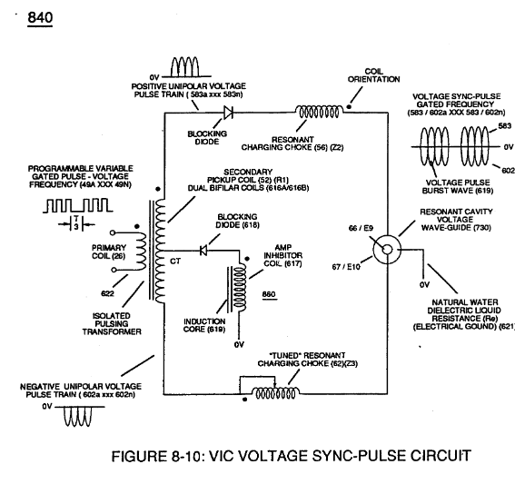
(840) of Figure (8-10) · 8-6 - VIC Voltage Sync-Pulse Circuit
-
Carries this number · WFC 427 Illustrations
-
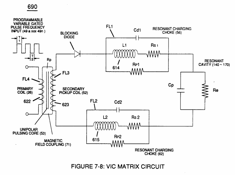
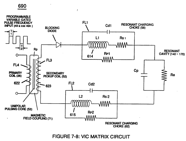
The figure it sits on · VIC Matrix Circuit
-
(T2) of Figure (7-8) · Instant Explosion of Water
-
Figure (7-8) · Resistance (Rs)
-
(690) of Figure (7-8) · Resistance (Rs)
-
(690) of Figure (7-8) · Inductance (FL)
-
(690) of Figure (7-8) · Capacitance (Cd)
-
(690) of Figure (7-8) · Inductance Reactance (Rs - Cd - FL)
-
Figure (7-8) · Inductance Reactance (Rs - Cd - FL)
-
(690) of Figure (7-8) · Taper Resonant Capacitor (ERt)
-
690 of Figure 7-8 · Circuit Resistance
-
(52) of Figure (7-8) · Electron Bounce Phenomenon
-
(690) of Figure (7-8) · 8-2 - Traveling Voltage Wave-Guides
-
(52) of Figure (7-8) · 8-3 - Electrical Voltage-Pulse Wave-Transmission
-
(Cp) of Figure (7-8) · 8-4 - State Space (Sp)
-
(690) of Figure (7-8) · 8-6 - VIC Voltage Sync-Pulse Circuit
-
(Cp) of (7-8) · 8-6 - VIC Voltage Sync-Pulse Circuit
-
(690) of Figure (7-8) · Propagating Electrical Stress
-
The figure it sits on · WFC 429 - Illustrations
Where it is named · 5
Instant Explosion of Water 1×
-
Switching Diode (55) of Figure (3-22) prevents Bidirectional electron flow (current flow in one direction only) since Blocking Diode (55) only conducts "current flow" in the direction of schematic-arrow while being placed in-line with VIC Circuit impedance interaction (R1 + Z2 + Z3 + Re), as mathematically extrapolated in Circuit Equation (Eq 9)
Circuit Resistance 1×
-
(Z2) is determined by inductance field strength (FL1) and resistive value (RS1) (typically 11.6 KQ) of stainless steel (s/s) wire-coil (56) (LI) when being exposed to external magnetic coupling field strength (Rp),
8-3 - Electrical Voltage-Pulse Wave-Transmission 1×
-
Resonant Charging Chokes (56/Z2 – 62/Z3)
The newly established leading voltage edge (Vpa) and trailing voltage edge (Vpb) being uniform in shape/configuration since both Resonant Charging Chokes (56/Z2 – 62/Z3) resistive values are the same (Typically 11.6 kΩ each) and incoming signal (49a xxx 49n) is electrically linked with Water-Gap Capacitor (Cp) of Figure (7-8) having dielectric liquid of Water (85) there between.
8-6 - VIC Voltage Sync-Pulse Circuit 2×
-
Resonant Choke Coils Electromagnetic Fields Intensity (+Z2 / -Z3)
… allowing Inductor Resonant Choke Coils Electromagnetic Fields Intensity (+Z2 / -Z3) to be, in turn, free of Electromagnetic variances of intensity (Z2 - Z3).
-
… allowing Inductor Resonant Choke Coils Electromagnetic Fields Intensity (+Z2 / -Z3) to be, in turn, free of Electromagnetic variances of intensity (Z2 - Z3).