patent · US5721795A
High efficiency ejection of light from optical wave guide, by holographically produced light scattering means
24 February 1998
Page 1 — bibliographic record
United States Patent (19) 11 Patent Number: 5,721.795 Pelka 45 Date of Patent: Feb. 24, 1998 54 HIGH EFFICIENCY EJECTION OF LIGHT 4,194,949 3/1980 Stark ....................................... 202/180 FROM OPTICAL WAVE GUIDE, BY 4,337,759 7/1982 Popovich et al...... ... 126/438 HOLOGRAPHICALLY PRODUCED LIGHT 4,749.248 6/1988 Aberson, Jr. et al. .................... 385/37 SCATTERING MEANS 4,755,921 7/1988 Nelson ................. ... 362/307 5,150,966 9/1992 Nelson .................................... 362/337 5,340,715 8/1994 Slovacek et al. ..................... 38.5/12X (75) Inventor: David G. Pelka, Los Angeles, Calif. 5,404,869 4/1995 Parkyn, Jr. et al. .................... 26W699 5,525,466 6/1996 Slovacek et al. ..................... 385.712 X (73) Assignee: TR Technologies, Inc.. Carson City,
Va. FOREIGN PATENT DOCUMENTS
(21) Appi. No.: 649,284 1325087 8/1973 United Kingdom. 22) Filed: May 17, 1996 1546791 5/1979 United Kingdom.
51) int. Cl. ............... G02B 6/34 1546793 5/1979 United Kingdom. 52 U.S. C. ...... ... 385/37:385/12: 385/38; 1557472 12/1979 United Kingdom. 385/129; 385/901 1561129 2/1980 United Kingdom.
58 Field of Search .................................. 385/37, 12,38, 2239940 12/1993 United Kingdom.
References Cited
Primary Examiner-Phan T. H. Palmer 56 Attorney, Agent, or Firm-William W. Haefliger
1421,506 7/1922 Limpert. Radiant electromagnetic energy transmitting apparatus, 3,915,148 10/1975 Fletcher et al. ......................... 26/27 comprising an elongated body consisting of electromagnetic 3,941,993 3/1976 Hubert ..................................... 240/14 3,970,070 7/1976 Meyer et al ... 126/271 energy transmitting material, the energy injected into the 4,002,031 1/1977 Bell ................. ... 126/271 body to travel therein and to be trapped during the travel by 4,022,186 5/1977 Northrup, Jr. ... 126/271 total internal reflecting off walls defined by the body, and 4,074,704 2/1978 Gellert ................ ... 126/270 there being at least one site within the body having varie 4,103,673 8/1978 Woodworth et al. ... ... 126/27 gated surface relief acting to scatter incident radiant energy 4,108,540 8/1978 Anderson et al. .. ... 350/211 for ejection from the body as rays defining a selected solid 4,116,223 9/1978 Vasilantone ..... ... 126/27 angle.
4,124,017 11/1978 Paul ........... ... 126/270 4,136,670 1/1979 Davis ..... ... 126/271 4,171,695 10/1979 Sletten .................................... 126/438 24 Claims, 4 Drawing Sheets
Page 2
Drawing sheet — no readable text.
Page 3
Drawing sheet — no readable text.
Page 4
Drawing sheet — no readable text.
Page 5
Drawing sheet — no readable text.
Page 6
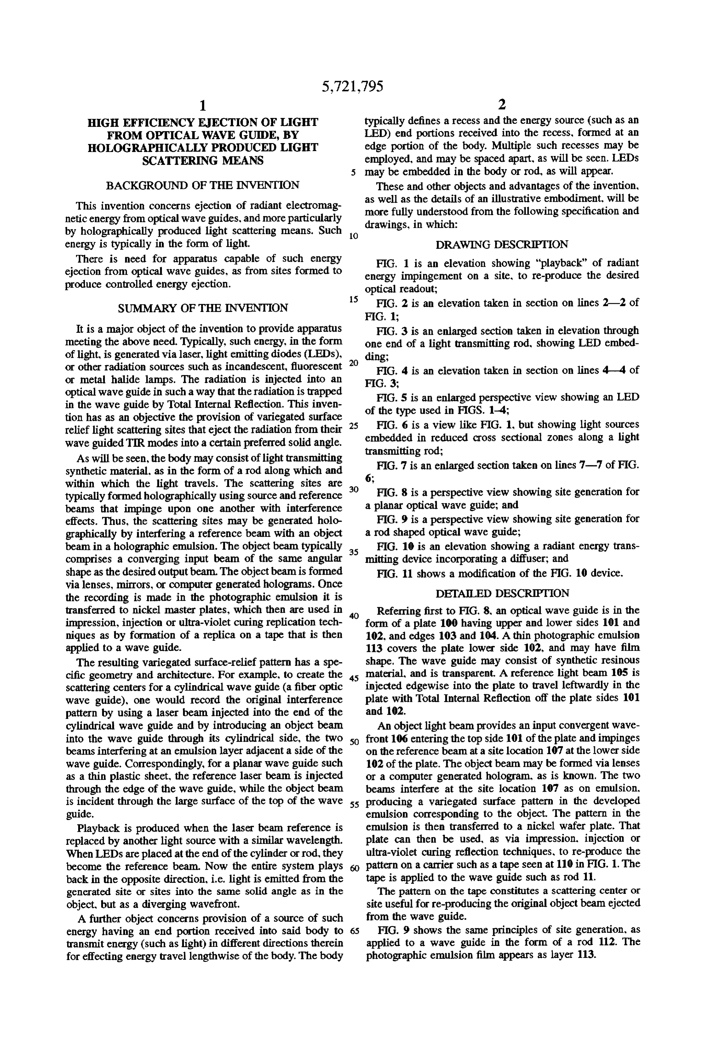
HIGH EFFICIENCY EJECTION OF LIGHT typically defines a recess and the energy source (such as an FROM OPTICAL WAVE GUIDE, BY LED) end portions received into the recess, formed at an HOLOGRAPHICALLY PRODUCED LGBT edge portion of the body. Multiple such recesses may be SCATTERNG MEANS employed, and may be spaced apart, as will be seen. LEDs may be embedded in the body or rod, as will appear.
BACKGROUND OF THE INVENTION These and other objects and advantages of the invention, This invention concerns ejection of radiant electromag as well as the details of an illustrative embodiment, will be more fully understood from the following specification and netic energy from optical wave guides, and more particularly drawings, in which:
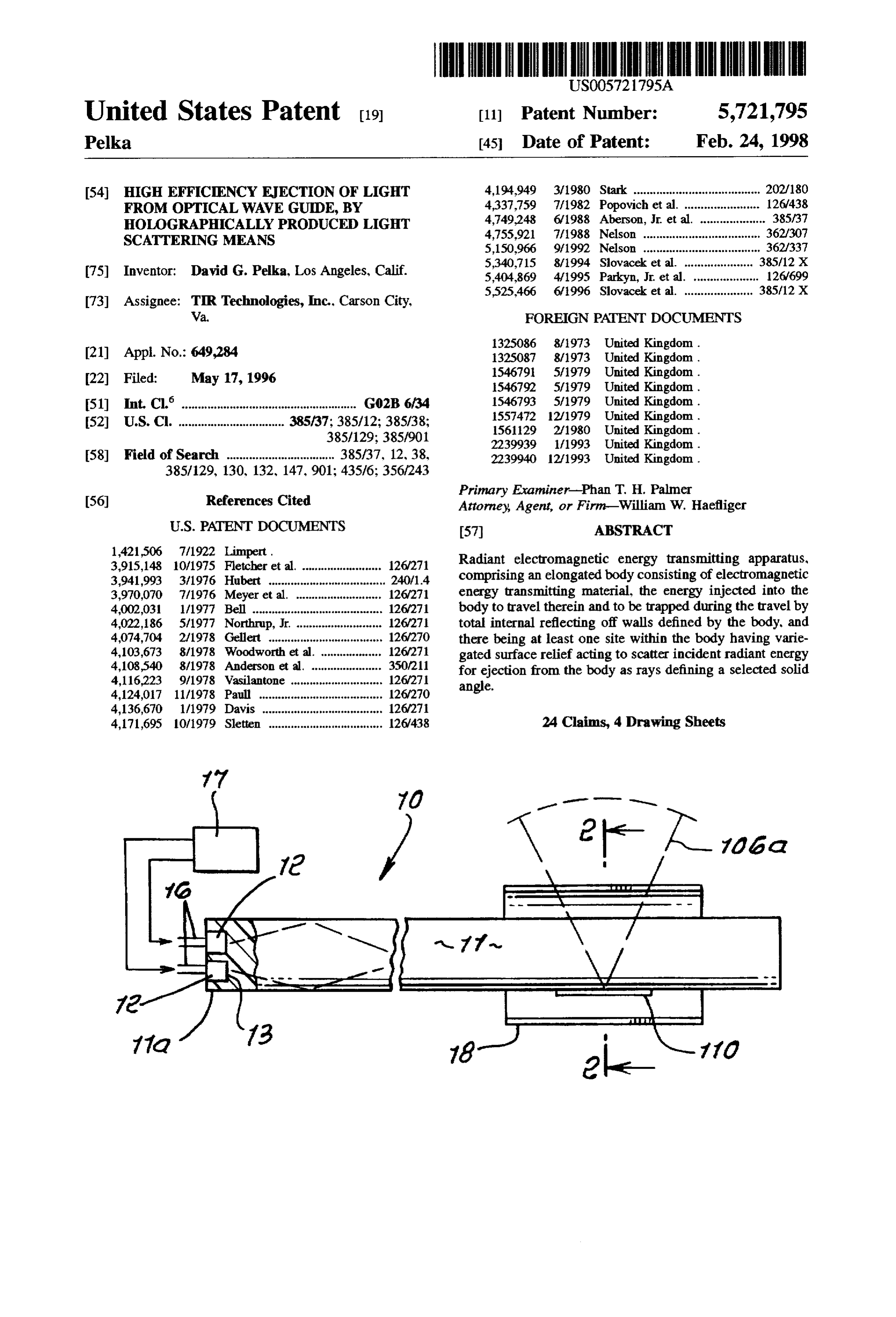
by holographically produced light scattering means. Such 10 energy is typically in the form of light. DRAWING DESCRIPTION There is need for apparatus capable of such energy FIG. 1 is an elevation showing "playback" of radiant ejection from optical wave guides, as from sites formed to energy impingement on a site, to re-produce the desired produce controlled energy ejection. optical readout;
15 FIG. 2 is an elevation taken in section on lines 2-2 of
SUMMARY OF THE INVENTION
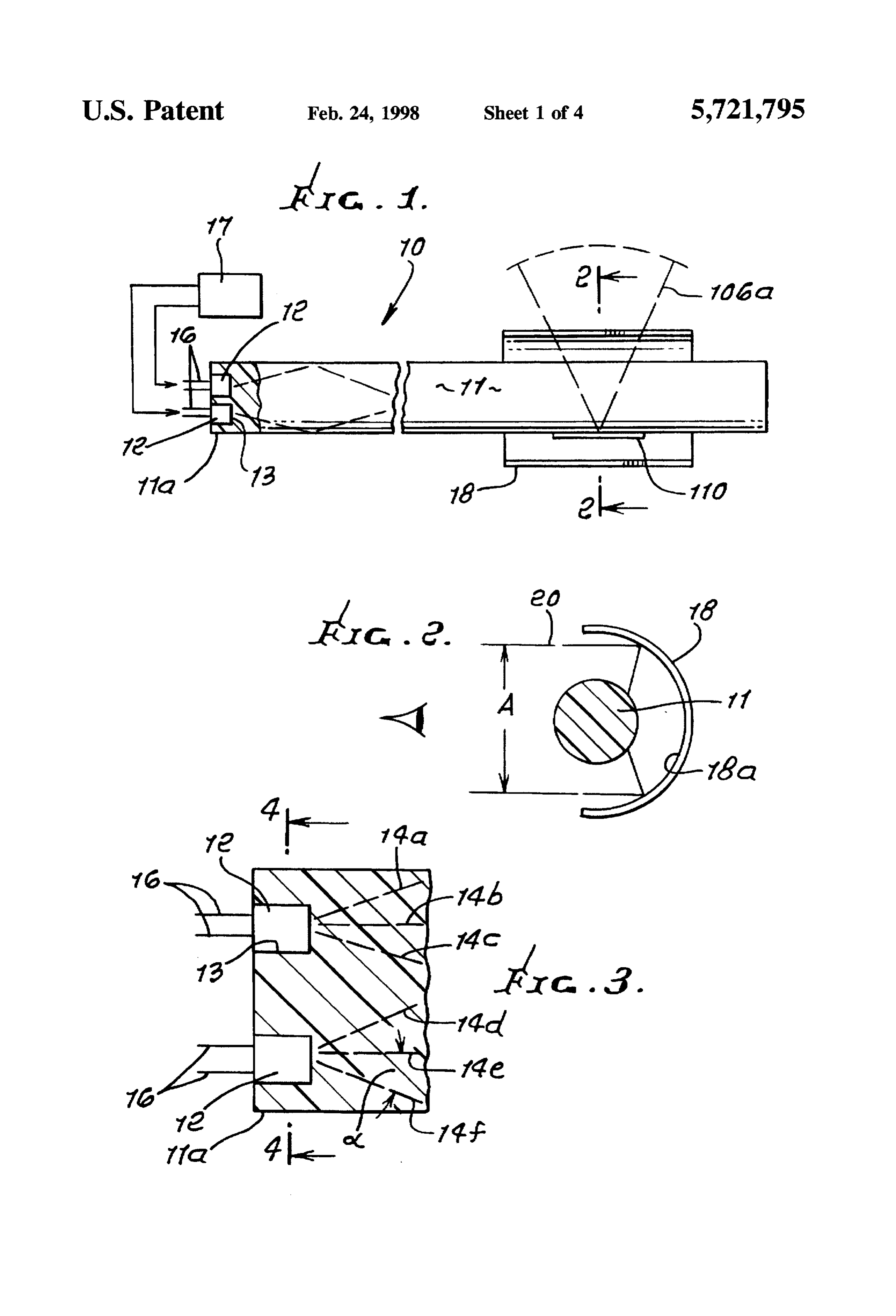
It is a major object of the invention to provide apparatus FIG. 3 is an enlarged section taken in elevation through meeting the above need. Typically, such energy, in the form one end of a light transmitting rod, showing LED embed of light, is generated via laser, light emitting diodes (LEDs), 20 ding;
or other radiation sources such as incandescent, fluorescent FIG. 4 is an elevation taken in section on lines 4-4 of or metal halide lamps. The radiation is injected into an FIG. 3;
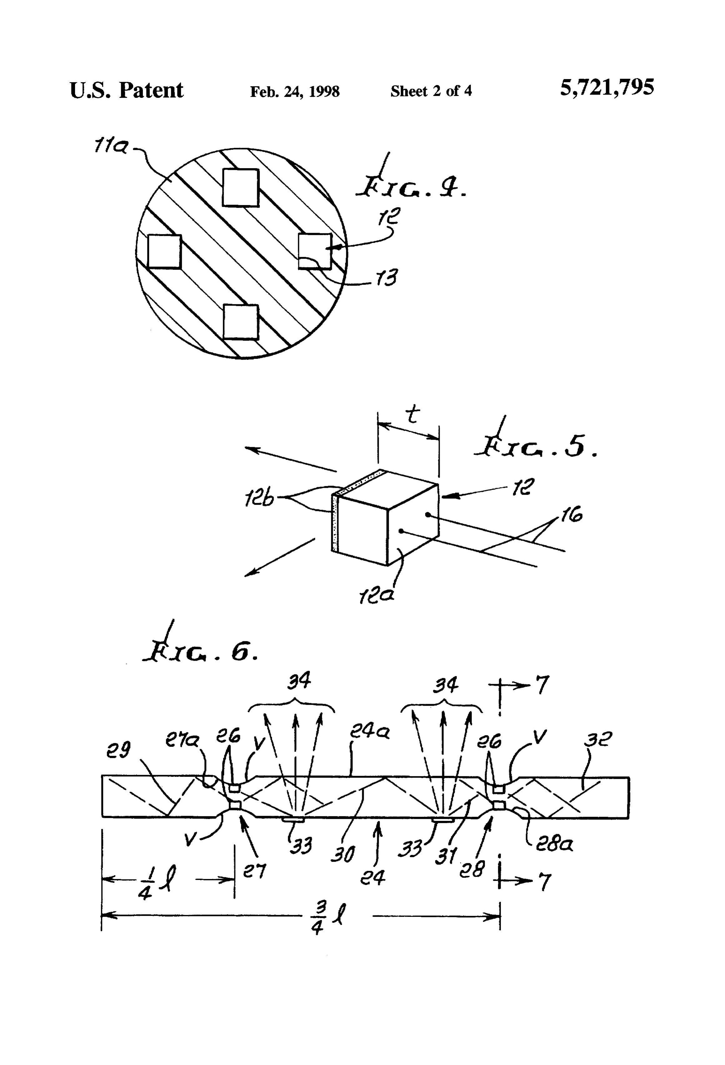
optical wave guide in such a way that the radiation is trapped in the wave guide by Total Internal Reflection. This inven of FIG. 5 is an enlarged perspective view showing an LED tion has as an objective the provision of variegated surface 25 FIG. 6 isused the type
view like FIG. 1, but showing light sources relief light scattering sites that eject the radiation from their embedded in reduced cross sectional zones along a light wave guided TIR modes into a certain preferred solid angle. transmitting rod;
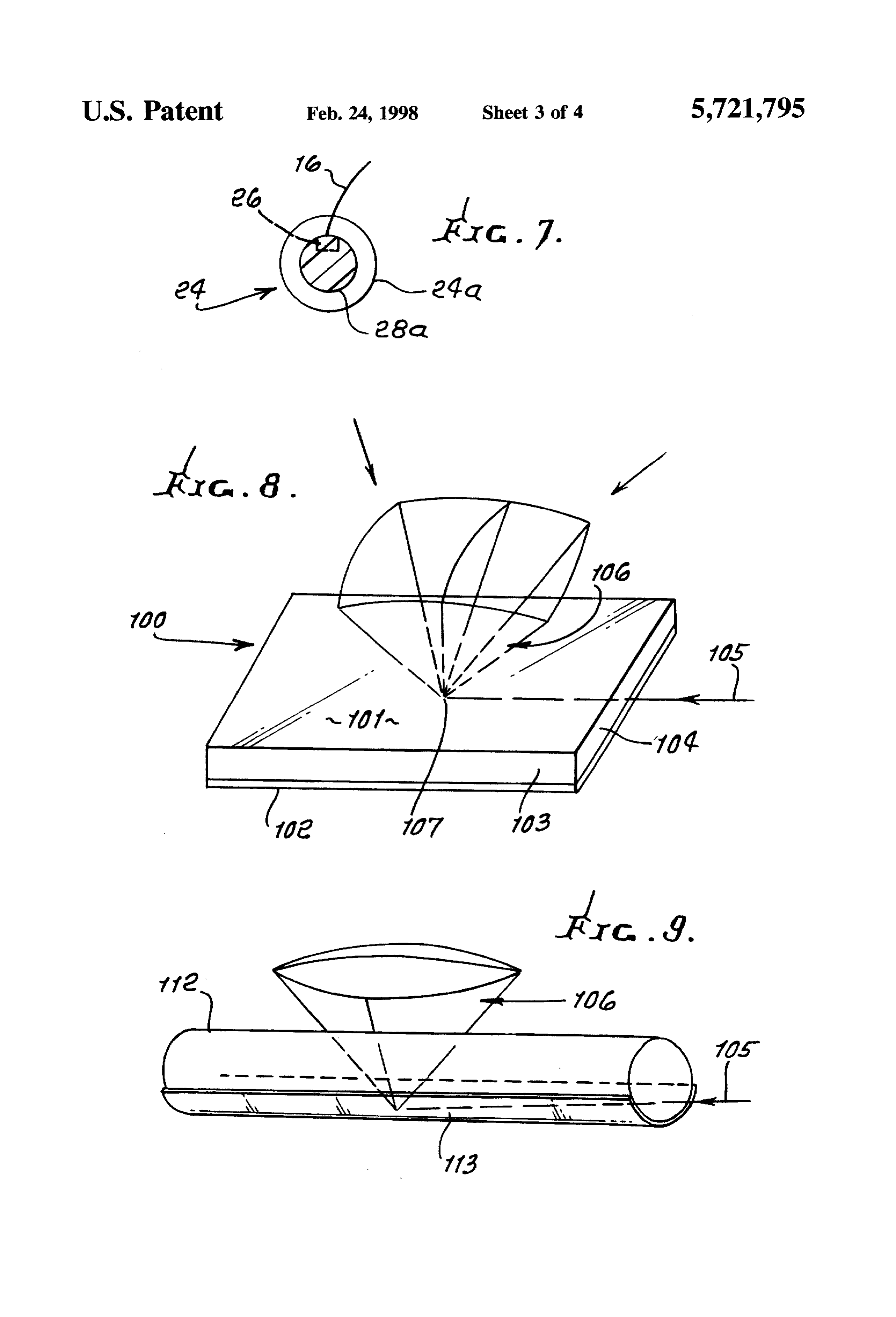
As will be seen, the body may consist of light transmitting synthetic material. as in the form of a rod along which and 6; FIG. 7 is an enlarged section taken on lines 7-7 of FIG. within which the light travels. The scattering sites are typically formed holographically using source and reference 30 FIG. 8 is a perspective view showing site generation for beams that impinge upon one another with interference a planar optical wave guide; and effects. Thus, the scattering sites may be generated holo FIG. 9 is a perspective view showing site generation for graphically by interfering a reference beam with an object a rod shaped optical wave guide;
beam in a holographic emulsion. The object beam typically 35 FIG. 10 is an elevation showing a radiant energy trans comprises a converging input beam of the same angular mitting device incorporating a diffuser; and shape as the desired output beam. The object beam is formed FIG. 11 shows a modification of the FIG. 10 device. via lenses, mirrors, or computer generated holograms. Once the recording is made in the photographic emulsion it is DETALED DESCRIPTION transferred to nickel master plates, which then are used in Referring first to FIG. 8, an optical wave guide is in the impression, injection or ultra-violet curing replication tech form of a plate 100 having upper and lower sides 101 and niques as by formation of a replica on a tape that is then 102, and edges 103 and 104. A thin photographic emulsion applied to a wave guide. 113 covers the plate lower side 102, and may have film The resulting variegated surface-relief pattern has a spe shape. The wave guide may consist of synthetic resinous cific geometry and architecture. For example, to create the 45 material, and is transparent. A reference light beam 105 is scattering centers for a cylindrical wave guide (a fiber optic injected edgewise into the plate to travel leftwardly in the wave guide), one would record the original interference plate with Total Internal Reflection off the plate sides 101 pattern by using a laser beam injected into the end of the and 102.
cylindrical wave guide and by introducing an object beam An object light beam provides an input convergent wave into the wave guide through its cylindrical side, the two SO front 106 entering the top side 101 of the plate and impinges beams interfering at an emulsion layer adjacent a side of the on the reference beam at a site location 107 at the lower side wave guide. Correspondingly, for a planar wave guide such 102 of the plate. The object beam may be formed via lenses as a thin plastic sheet, the reference laser beam is injected or a computer generated hologram, as is known. The two through the edge of the wave guide, while the object beam beams interfere at the site location 107 as on emulsion, is incident through the large surface of the top of the wave 55 producing a variegated surface pattern in the developed guide. emulsion corresponding to the object. The pattern in the Playback is produced when the laser beam reference is emulsion is then transferred to a nickel wafer plate. That replaced by another light source with a similar wavelength. plate can then be used, as via impression, injection or When LEDs are placed at the end of the cylinder or rod, they ultra-violet curing reflection techniques, to re-produce the become the reference beam. Now the entire system plays pattern on a carrier such as a tape seen at 110 in FIG. 1. The back in the opposite direction, i.e. light is emitted from the tape is applied to the wave guide such as rod 11. generated site or sites into the same solid angle as in the The pattern on the tape constitutes a scattering center or object, but as a diverging wavefront. site useful for re-producing the original object beam ejected A further object concerns provision of a source of such from the wave guide.
energy having an end portion received into said body to 65 FIG. 9 shows the same principles of site generation, as transmit energy (such as light) in different directions therein applied to a wave guide in the form of a rod 112. The for effecting energy travel lengthwise of the body. The body photographic emulsion film appears as layer 113.
Page 7
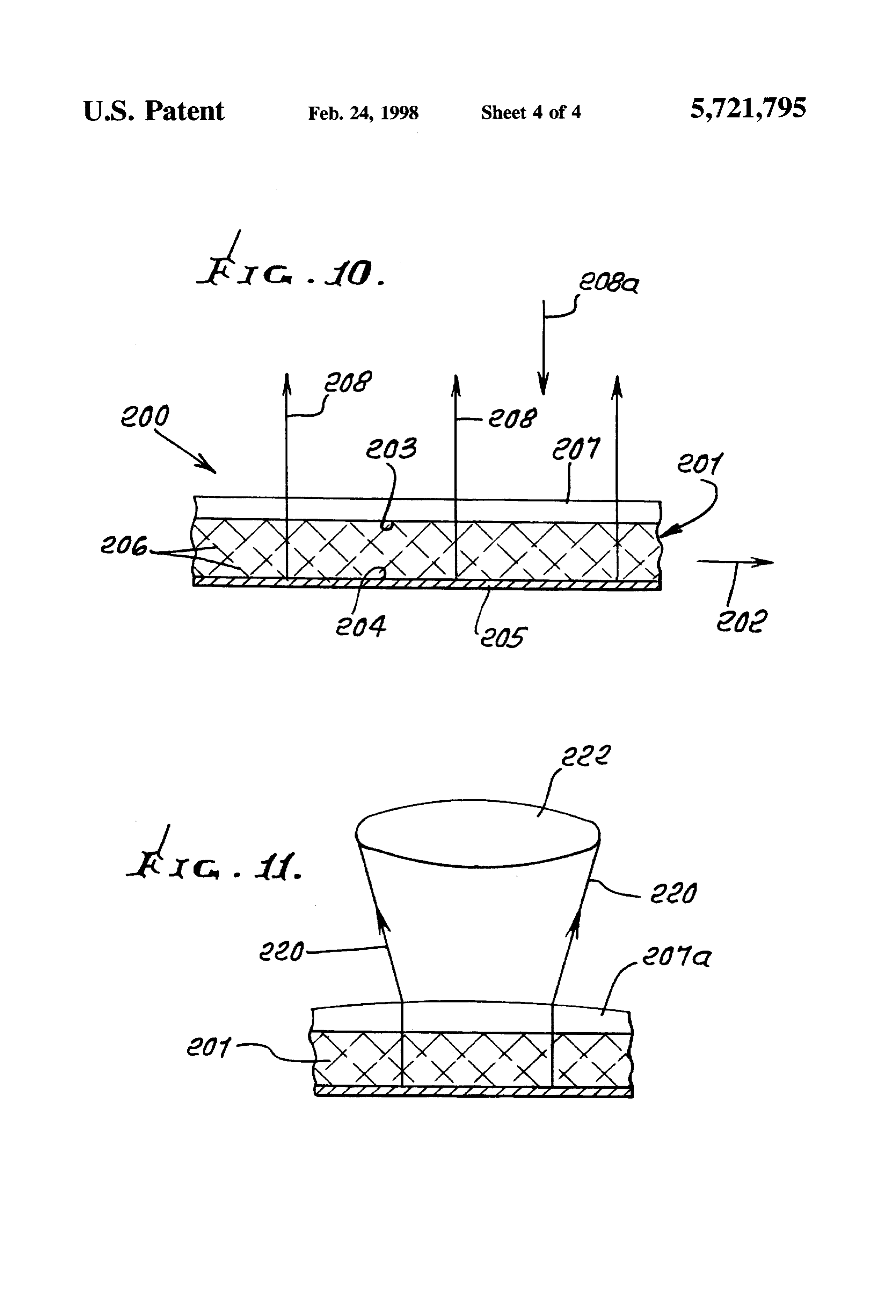
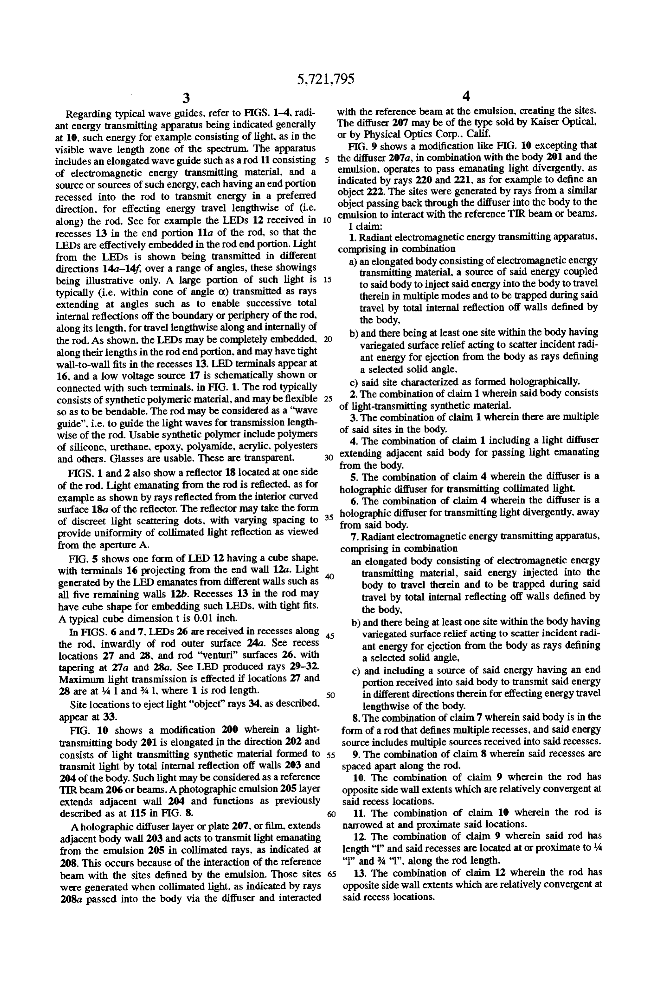
Regarding typical wave guides, refer to FIGS. 1-4, radi with the reference beam at the emulsion, creating the sites. ant energy transmitting apparatus being indicated generally The diffuser 207 may be of the type sold by Kaiser Optical, at 10, such energy for example consisting of light, as in the or by Physical Optics Corp., Calif.
visible wave length zone of the spectrum. The apparatus FIG. 9 shows a modification like FIG. 10 excepting that includes an elongated wave guide such as a rod 11 consisting the diffuser 207a, in combination with the body 201 and the of electromagnetic energy transmitting material, and a emulsion, operates to pass emanating light divergently, as source or sources of such energy, each having an end portion indicated by rays 220 and 221, as for example to define an object 222. The sites were generated by rays from a similar recessed into the rod to transmit energy in a preferred object passing back through the diffuser into the body to the direction, for effecting energy travel lengthwise of (i.e. emulsion to interact with the reference TIR beam or beams. along) the rod. See for example the LEDs 12 received in 10
I claim:
recesses 13 in the end portion 11a of the rod, so that the 1. Radiant electromagnetic energy transmitting apparatus, LEDs are effectively embedded in the rod end portion. Light comprising in combination from the LEDs is shown being transmitted in different a) an elongated body consisting of electromagnetic energy directions 14a-14f over a range of angles, these showings transmitting material, a source of said energy coupled being illustrative only. A large portion of such light is 15 to said body to inject said energy into the body to travel typically (i.e. within cone of angle or) transmitted as rays therein in multiple modes and to be trapped during said extending at angles such as to enable successive total travel by total internal reflection off walls defined by internal reflections off the boundary or periphery of the rod, the body.
along its length, for travel lengthwise along and internally of the rod. As shown, the LEDs may be completely embedded, 20 b) variegatedand there being at least one site within the body having surface relief acting to scatter incident radi along their lengths in the rod end portion, and may have tight ant energy for ejection from the body as rays defining wall-to-wall fits in the recesses 13. LED terminals appear at a selected solid angle.
16, and a low voltage source 17 is schematically shown or c) said site characterized as formed holographically. connected with such terminals, in FIG. 1. The rod typically 2. The combination of claim 1 wherein said body consists consists of synthetic polymeric material, and may be flexible of light-transmitting
synthetic material.
so as to be bendable. The rod may be considered as a "wave guide", i.e. to guide the light waves for transmission length of 3.said The combination of claim 1 wherein there are multiple sites in the body.
wise of the rod. Usable synthetic polymer include polymers 4. The combination of claim 1 including a light diffuser of silicone, urethane, epoxy, polyamide, acrylic, polyesters extending adjacent said body for passing light emanating and others. Glasses are usable. These are transparent. from the body.
FIGS. 1 and 2 also show a reflector 18 located at one side 5. The combination of claim 4 wherein the diffuser is a of the rod. Light emanating from the rod is reflected, as for holographic diffuser for transmitting collimated light. example as shown by rays reflected from the interior curved 6. The combination of claim 4 wherein the diffuser is a surface 18a of the reflector. The reflector may take the form 35 holographic diffuser for transmitting light divergently, away of discreet light scattering dots, with varying spacing to from said body.
provide uniformity of collimated light reflection as viewed 7. Radiant electromagnetic energy transmitting apparatus, from the aperture A. comprising in combination
FIG. 5 shows one form of LED 12 having a cube shape, an elongated body consisting of electromagnetic energy with terminals 16 projecting from the end wall 12a. Light transmitting material, said energy injected into the generated by the LED emanates from different walls such as body to travel therein and to be trapped during said all five remaining walls 12b. Recesses 13 in the rod may travel by total internal reflecting off walls defined by have cube shape for embedding such LEDs, with tight fits. the body,
A typical cube dimension t is 0.01 inch. b) and there being at least one site within the body having In FIGS. 6 and 7. LEDs 26 are received in recesses along 45 variegated surface relief acting to scatter incident radi the rod, inwardly of rod outer surface 24a. See recess ant energy for ejection from the body as rays defining locations 27 and 28, and rod "venturi" surfaces 26, with a selected solid angle, tapering at 27a and 28a. See LED produced rays 29-32. c) and including a source of said energy having an end Maximum light transmission is effected if locations 27 and portion received into said body to transmit said energy 28 are at 4 1 and %. 1, where 1 is rod length. in different directions therein for effecting energy travel Site locations to eject light "object" rays 34, as described, lengthwise of the body.
appear at 33. 8. The combination of claim 7 wherein said body is in the FIG. 10 shows a modification 200 wherein a light form of a rod that defines multiple recesses, and said energy transmitting body 201 is elongated in the direction 202 and source includes multiple sources received into said recesses. consists of light transmitting synthetic material formed to 55. 9. The combination of claim 8 wherein said recesses are transmit light by total internal reflection off walls 203 and spaced apart along the rod.
204 of the body. Such light may be considered as a reference 10. The combination of claim 9 wherein the rod has TIR beam 206 or beams. A photographic emulsion 205 layer opposite side wall extents which are relatively convergent at extends adjacent wall 204 and functions as previously said recess locations.
described as at 115 in FIG. 8. 11. The combination of claim 10 wherein the rod is Aholographic diffuser layer or plate 207, or film, extends narrowed at and proximate said locations. adjacent body wall 203 and acts to transmit light emanating 12. The combination of claim 9 wherein said rod has from the emulsion 205 in collimated rays, as indicated at length "l" and said recesses are located at or proximate to 4 208. This occurs because of the interaction of the reference "l" and % "I", along the rod length.
beam with the sites defined by the emulsion. Those sites 65 13. The combination of claim 12 wherein the rod has were generated when collimated light, as indicated by rays opposite side wall extents which are relatively convergent at 208a passed into the body via the diffuser and interacted said recess locations.
Page 8
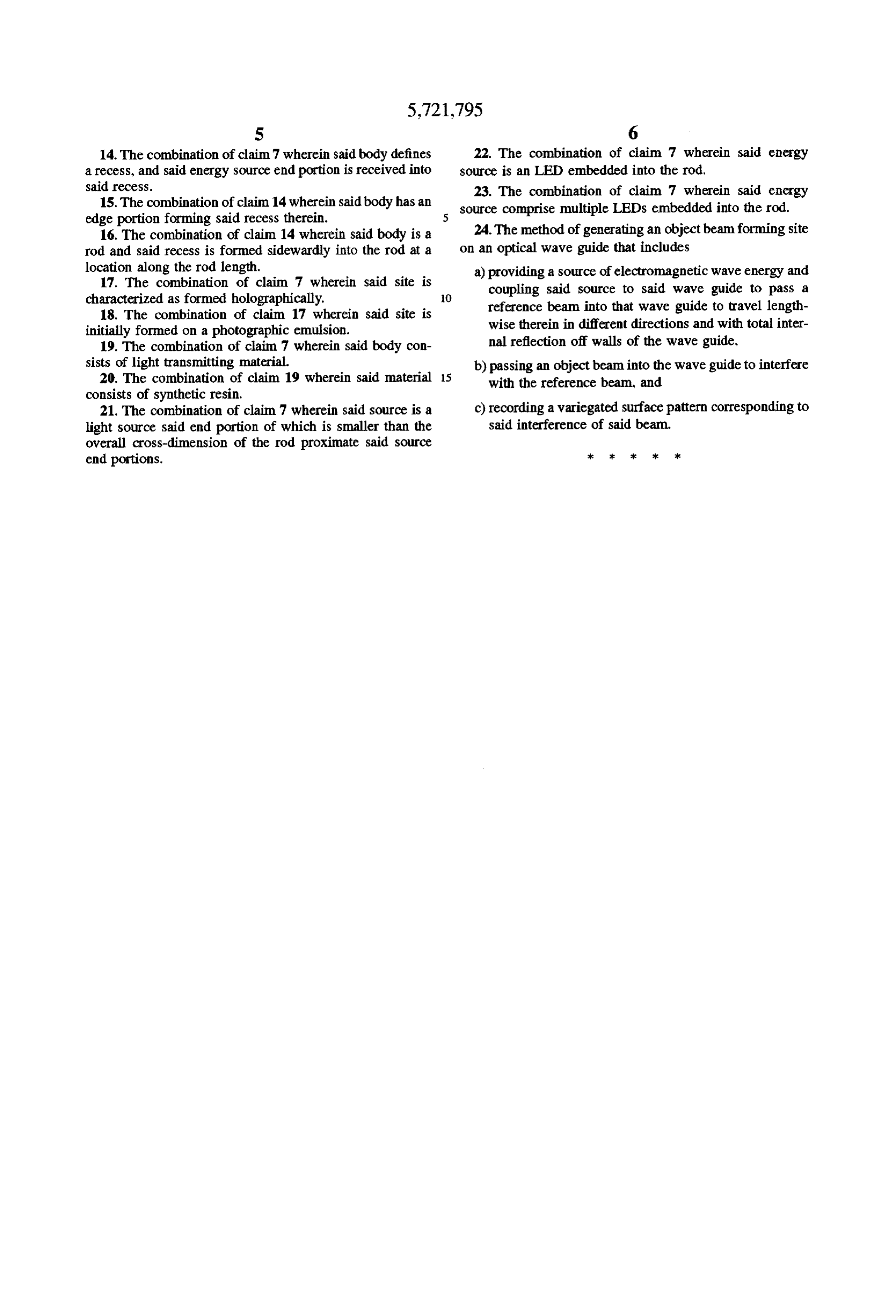
S 6 14. The combination of claim 7 wherein said body defines 22. The combination of claim 7 wherein said energy a recess, and said energy source end portion is received into source is an LED embedded into the rod, said recess. 23. The combination of claim 7 wherein said energy 15. The combination of claim 14 wherein said body has an source comprise multiple LEDs embedded into the rod. edge portion forming said recess therein. 5 16. The combination of claim 14 wherein said body is a 24. The method of generating an object beam forming site rod and said recess is formed sidewardly into the rod at a on an optical wave guide that includes location along the rod length. a) providing a source of electromagnetic wave energy and 17. The combination of claim 7 wherein said site is coupling said source to said wave guide to pass a characterized as formed holographically, O reference beam into that wave guide to travel length 18. The combination of claim 17 wherein said site is initially formed on a photographic emulsion. wise therein in different directions and with total inter 19. The combination of claim 7 wherein said body con nal reflection off walls of the wave guide, sists of light transmitting material. b) passing an object beam into the wave guide to interfere 20. The combination of claim 19 wherein said material 15 with the reference beam, and consists of synthetic resin.
21. The combination of claim 7 wherein said source is a c) recording a variegated surface pattern corresponding to light source said end portion of which is smaller than the said interference of said beam. overall cross-dimension of the rod proximate said source end portions. 3k se ck sk 2k
Provenance
- Collection
- Patents citing this work
- Original assignee
- TIR Technologies Inc
- Current assignee
- Teledyne Technologies Inc
- Pages
- 8
- Method
- pdftotext (the PDF's own text layer) + pdftoppm 300dpi page scans
- Patent office record
- patents.google.com →
- Source
- Google Patents citing-documents table
- Inventors
- David G. Pelka; TIR Technologies Inc
- Published
- 1998-02-24
- Transcribed from
- patentimages.storage.googleapis.com →