patent · US4749248
Device for tapping radiation from, or injecting radiation into, single made optical fiber, and communication system comprising same
7 June 1988
Page 1 — bibliographic record
United States Patent (19) 11 Patent Number: 4,749,248 Aberson, Jr. et al. 45) Date of Patent: Jun. 7, 1988 54, DEVICE FORTAPPENGRADIATION FROM, Optical Engineering, vol. 17(5), pp. 470-479 (1978), by OR INJECTING RADIATION INTO, SINGLE A. M. Glass, "The Photorefractive Effect'. MADE OPTICAL FIBER, AND Primary Examiner-Eugene R. LaRoche
COMMUNICATION SYSTEM COMPRISING
SAME Assistant Examiner-James C. Lee
Attorney, Agent, or Firm-Eugen E. Pacher 75 Inventors: James A. Aberson, Jr., Atlanta; Ian 57 ABSTRACT A. White, Roswell, both of Ga.
73 Assignee: American Telephone and Telegraph Optical radiation can be efficiently removed from, or Company AT&T Bell Laboratories, injected into, single mode optical fiber at an intermedi Murray Hill, N.J. ate point along the fiber, by causing quasi-resonant coupling of the guided mode LPol to an appropriate 21 Appl. No.: 795,482 tunneling leaky (TL) mode, e.g., LP11. Such coupling is (22 Filed: Nov. 6, 1985 caused by means of a "grating' in the fiber, with the grating being formed by impressing a periodic (or pseu 51 Int. Cl'................................................ GO2B 6/34 do-periodic) modulation on the fiber, or by causing a 52 U.S. C. .............................. 350/96.19; 350/96.15; periodic (or pseudo-periodic) variation of the refractive 350/96.16 index of the fiber by means of the photoelastic or the 58) Field of Search ................ 350/96.15, 96.16, 96.19 photorefractive effect. The nominal grating spacing 56) References Cited A(z) is chosen such that ()a=(27T/A)>go1-27tnci/No,
gation constant of the LPol mode, inci is the refractive 3,883,221 5/1975 Rigrod ............................. 350/96.9 index of the fiber cladding, and Nois the wavelength of 3,931,518 1/1976 Miller .................................. 250/227 the radiation to be coupled from or into the fiber. Fur 4,135,780 1/1979 Dyott ............................... 350/96.15 thermore, A(z) is to be chosen such that 2-Aol-As,
where 3sis the propagation constant of the selected TL
OTHER PUBLICATIONS mode. In order for the coupling to be quasi-resonant, it Theory of Dielectric Optical Waveguides, Academic is necessary that as the attenuation constant of the Press, 1974, by D. Marcuse, pp. 95-157. selected TL mode, be relatively small, typically <1 Digest of Technical Papers of the Conference on Optical dB/cm. By appropriately choosing A(z) and/or the Fiber Communication, New Orleans, La., Jan. 1984, by amplitude function of the grating, it is possible to in N. Lagakos, pp. 56-58. crease the coupling efficiency above what is possible First International Conference on Optical Fibre Sensors, with a constant spacing, constant amplitude grating. London, Apr. 1983, pp. 117-121. Devices according to the invention can be advanta Appl. Phys. Lett. 41(2), 15 Jul. 1982, "Microbend Optical geously used not only as radiation couplers but also as Fiber Tapped Delay Line for Gigahertz Signal Process filters and, if they are of the photorefractive type, as ing', by K. P. Jackson et al., pp. 139-141. amplitude modulators.
Applied Optics, vol. 10, No. 10, Oct. 1971, “Weakly
Guiding Fibers', by D. Gloge, pp. 2252-2258. 17 Claims, 4 Drawing Sheets
Page 2
Drawing sheet — no readable text.
Page 3
Drawing sheet — no readable text.
Page 4
Drawing sheet — no readable text.
Page 5
Drawing sheet — no readable text.
Page 6
with multimode fiber but also with single mode fiber,
DEVICE FORTAPPING RADIATION FROM, OR this type of coupler has in fact only been used in con INJECTING RADIATION INTO, SINGLEMADE junction with multimode fibers. The reason for this is as OPTICAL FIBER, AND COMMUNICATION follows. It is generally understood in the art that the SYSTEM COMPRSNG SAME coupling process between bound modes in multimode fiber is a resonance process, and that consequently the
FIELD OF THE INVENTION coupling parameters can be adjusted to result in effi This invention pertains to devices for coupling opti cient resonant power transfer into high order bound cal power from and/or into optical fiber, and to optical O modes, and from there nonresonantly into TL modes. fiber communication systems comprising such devices. On the other hand, the theory teaches that, in single
BACKGROUND OF THE INVENTION
mode fiber, the coupling between LPol, the bound mode, and a TL mode, e.g., LP11, is nonresonant, such
Optical communications has undergone very rapid that the radiation amplitude in LPo1 decreases exponen development, to the point where optical fiber transmis tially with distance along the propagation direction, due sion systems are becoming almost commonplace. Opti 15 to the continuous transfer to the TL mode of a constant cal fiber is not only used for trunk (i.e., long-haul) appli fraction of the power in LPo1. See, for instance, page cations, but also to transfer information over short dis 112 of the above cited book by Marcuse, where it is tances, e.g., in local area networks, and potentially, in stated that, for the case of a single-mode guide, the the subscriber loop. power coupled into TL (radiation) modes is radiated In many applications it is necessary, or at least desir 20 from the guide and does not interact with the guided able, to inject optical power into a fiberguide at inter mode. Since such nonresonant coupling cannot be mediate locations, and/or to extract optical power from tuned to result in efficient power transfer between LPol the fiberguide at such locations, without the need for and TL modes, it is generally accepted in the art that breaking or terminating the fiberguide, and without fiber taps of the "grating' type cannot be made to func requiring special preparation of the coupling point in 25 tion efficiently in single mode fiber. the fiberguide. Such couplers have been known in the The fact that microbending-induced mode coupling art for some time. See, for instance, co-assigned U.S. in multimode fibers can involve a resonance mechanism Pat. No. 3,931,518, (518), issued Jan. 6, 1976, to S. E. has also been used to construct highly sensitive fiber Miller, which teaches a particular embodiment of a optic displacement sensors. See, for instance, N. Laga coupler type which will herein be referred to as a "grat 30 kos, Digest of Technical Papers of the Conference on Opti ing' coupler. cal Fiber Communication, New Orleans, La., January The 518 patent teaches that optical power can be coupled from an optical fiber by impressing a periodic 1984, pp. 56-58.
deformation onto the fiber, with the periodicity of the on G.Optical F. Lipscomb et al, First International Conference Fiber Sensors, London, April 1983, pp.
deformation chosen such as to induce coupling between 117-121, report
on the result of experiments with single appropriate modes of radiation. In this fashion power mode and multimode optical fiber, in which a single can be transferred resonantly from lower to higher bend was induced in the fiber by bending the latter order guided or bound modes, and nonresonantly from the higher bound modes to the so-called tunneling leaky around a cylindrical mandrel. Interference effects be (TL) modes, which are then removed from the cladding tween bound modes and TL modes were observed in of the fiberguide with the aid of a dielectric body that is both types of fiber. In particular, it was observed that in contact with the fiberguide at a point downstream the bending causes some of the core-mode power to from the periodic deformation region and which has a convert into the cladding-mode power and, at specific refractive index which is approximately equal to or angles, some of the cladding-mode power to convert greater than the index of refraction of the cladding. back into core-mode power. It will be noted that the For an exposition of the relevant theory, see, for interference effects in the single-bend configuration of instance, D. Marcuse, Theory of Dielectric Optical Wave Lipscomb et all are not the desired resonance coupling guides, Academic Press, 1974, especially pages 95-157. effects that are of concern in this application. In this Briefly, it can be shown that it is possible to provide a respect, see also pages 156-157 of the above cited book coupling mechanism in multimode fiber such that the (i, 50 by Marcuse.
j)'th and (p, q)'th bound modes are coupled to produce K. P. Jackson et al Applied Physics Letters, Vol. 41(2), complete, energy exchange over a coupling length pp. 139-141 (1982) report on a tapped single mode opti Lic=t/Rjpg, where the coupling constant Ripa de cal fiber delay line. The taps were formed by urging a pends upon fiber parameters such as the core radius, the tapping pin against the fiber, thereby inducing a 1.5 mm refractive index difference between core and cladding, 55 bend radius in the fiber. No resonant coupling is in the operating wavelength, the fiber profile shape, and, volved in this technique.
in a coupler as disclosed in 518, on the amplitude of the Since single mode optical fiber is rapidly becoming distortion of the fiber. As the distortion amplitude in the fiber type of choice for long distance transmission, creases, the coupling length Lc decreases. Thus, a prior and is considered to be a promising medium even for art coupler as disclosed in 518 can be tuned for maxi 60 short-haul applications in which a multiplicity of send mum efficiency by adjusting the amplitude of the distor ing and/or receiving stations are connected by a single tions of the multimode fiber, to result in resonant energy or dual fiber transmission path, it is clear that it would transfer from low to higher order bound modes. be very desirable to have available efficient means for Although 518 teaches that optical power can be coupling optical power into, and/or out of, single mode coupled from the single guided mode (usually referred 65 optical fiber without breaking the fiber and without to as the LPo1 mode) of single mode fiber to one or more permanently changing the characteristics of the fiber in of the TL modes of such fiber, and that, therefore, cou the coupling region. This application discloses such plers of the type disclosed in 518 could be used not only coupling means.
Page 7
GLOSSARY OF TERMS that Qas (2TA)> go1-2arnel/Ao, where A is the aver age repeat spacing, go is the propagation constant of
An "optical fiber' (or fiberguide, or other equivalent the LPo mode in the fiber, and nois the refractive index term) is an elongated body comprising an interior re of the fiber cladding. Furthermore, in such a device gion (the core) having a higher refractive index (at the according to the invention the grating spacing A(z) is signal wavelength A) than the region surrounding the chosen such that (2 - 301-6, where 3s is the propa core, the cladding. Optical fiber can comprise cladding gation constant of a TL mode LPs in the fiber. This having a multiplicity of regions differing from each other with respect to the refractive index, and typically energy of choice repeat distance can result in quasi-resonant transfer between LPo1 and LPs (and adjacent is enveloped by a coating, or multiple coatings. The O modes), provided coating typically is a polymer and may be transparent the distance NA. A the power loss from LPsis small over (and in fiber used in practicing the invention typically is typical upper limit on the attenua transparent) to the radiation coupled into or from the tionThe constant an of the LP mode is about 1 dB/cm. grating can be produced by any appropriate fiber.
means, including by urging one, or a pair of, suitably
In optical communications systems frequently two or 15 corrugated more lengths of fiber are spliced or otherwise joined bodies against the fiber, thereby impressing together to form a continuous optical transmission path deformations on the fiber, or by appropriately changing from a first fiber end to a second fiber end. One end the refractive index of the fiber, for instance by means often can be considered to be the input end and the of the photorefractive or of the photoelastic effect. other the output end of the transmission path. However, 20 The grating can have constant amplitude, or the an it is possible to operate a system such that a given path plitude can be a function of z. Furthermore, the grating carries signals in both directions, with sending and re can be periodic, i.e., with A being constant, or it can be ceiving means at each fiber end. pseudo-periodic, with the repeat spacing being a func The radiation guided in an optical fiber, or radiated tion of z. Appropriately shaped nonconstant amplitude therefrom, can be described in terms of "modes' of 25 may result in improved coupling between the fiber and radiation. Herein the nomenclature introduced by D. an external radiation detector or radiation source, as Gloge, Applied Optics, Vol. 10, pp. 2252-2258 (1971) is will be described in detail below. Use of pseudo-peri used to identify the modes. With each mode LP can be odic gratings may, inter alia, result in a coupler having associated an attenuation constant aj and a propagation enhanced frequency dependence. Such a coupler may,
"Tunneling leaky"(TL) modes in single mode fiber inter alia, be useful as a notch filter. The "shaping' of the grating to thereby increase coupling efficiency, are the low order radiating modes (LP11, LP12, LP21, . frequency response, or other device characteristic, is ... ) that have relatively small attenuation constants.
"Coupler' herein refers both to means for extracting considered to be a significant aspect of the invention. optical power from an optical fiber at an intermediate 35 Due to the fact that devices according to the inven fiber location, and to means for injecting optical power tion can be made to be highly wavelength selective, into an optical fiber at an intermediate fiber location. such devices are considered to be potentially of utility A "grating' herein is an intermediate fiber region in as wavelength-dependent couplers in wavelength divi which the transmission characteristics of the fiber are sion multiplexed systems, or in Raman amplified soliton varying in a periodic or pseudo-periodic fashion. A systems. Devices according to the invention are also grating comprises N elements, with repeat length A(z), potentially useful as notch filters, as photorefractive where Z is the longitudinal fiber coordinate. Associated modulators, or as variable attenuators. Attenuators ac with the grating is an "envelope amplitude' described cording to the invention possess a highly advantageous by an "envelope' function g(z) that can be a constant or feature not typically found in prior art attenuators, vary as a function of z. The fiber characteristics vary in 45 namely, they do not cause power to be reflected back to a "periodic' manner if A(z) is a constant, and they vary the radiation source. Such reflection may affect the in a "pseudo-periodic' manner if A(z) is a regular and emission characteristics of sensitive sources and thus is predetermined function of z. The "amplitude' of an undesirable. Furthermore, gratings according to the element of a grating is the maximum fiber axis displace invention can be used in temporary taps such as are ment, or the maximum refractive index change, associ 50 frequently required for repair or reconfiguration pur ated with the element. poses. In such cases, the grating can advantageously be SUMMARY OF THE INVENTION incorporated into a clamp-on device. Such devices can The invention comprises means for efficiently cou be as used with coated or buffered individual fiber as well with laminated ribbon fibers.
pling electromagnetic radiation of wavelength A into 55 Disclosed is also an optical fiber communications or from an intermediate part of a single mode optical system comprising a source of radiation of wavelength fiber, i.e., withoutbreaking or terminating the fiber, and A, a single mode optical fiber, means for coupling the typically without permanently modifying the transmis sion properties of the fiber, e.g., by removal of all or radiation into the fiber at a first fiber location, means for part of the cladding material at the coupling location. detecting the radiation, after its transmission through The coupling means comprises means for forming a the fiber, at a second fiber location spaced apart from. grating, e.g., means for locally changing the optical the first location, means for coupling radiation (of characteristics of the fiber by impressing a multiplicity wavelength A, or possibly of wavelength AA-A) into of regularly (periodically or pseudo-periodically) and/or from the fiber at a third fiber location intermedi spaced deformations on the fiber, or by changing the 65 ate the first and second locations, with the coupling refractive index of the fiber in a multiplicity of regularly means being of the type described above. The system spaced fiber regions. In a coupling device according to optionally may comprise couplers according to the the invention the grating spacing A(z) is chosen such invention used as attenuators, filters, or modulators.
Page 8
BRIEF DESCRIPTION OF THE ORAWINGS 1 dB/cm, we currently consider 1 dB/cm to be a realis tic upper limit of the permissible attenuation of the
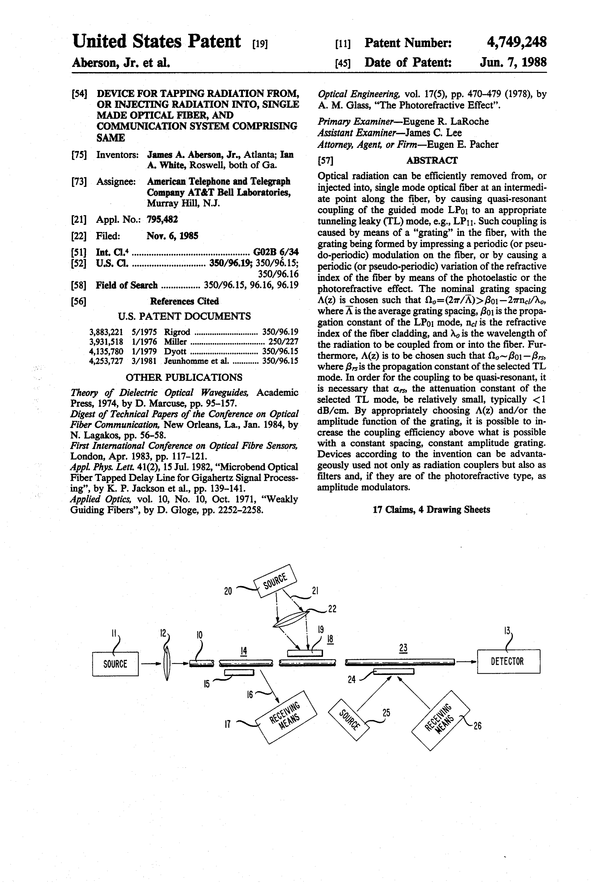
FIG. 1 schematically shows an exemplary fiberguide selected TL mode or modes.
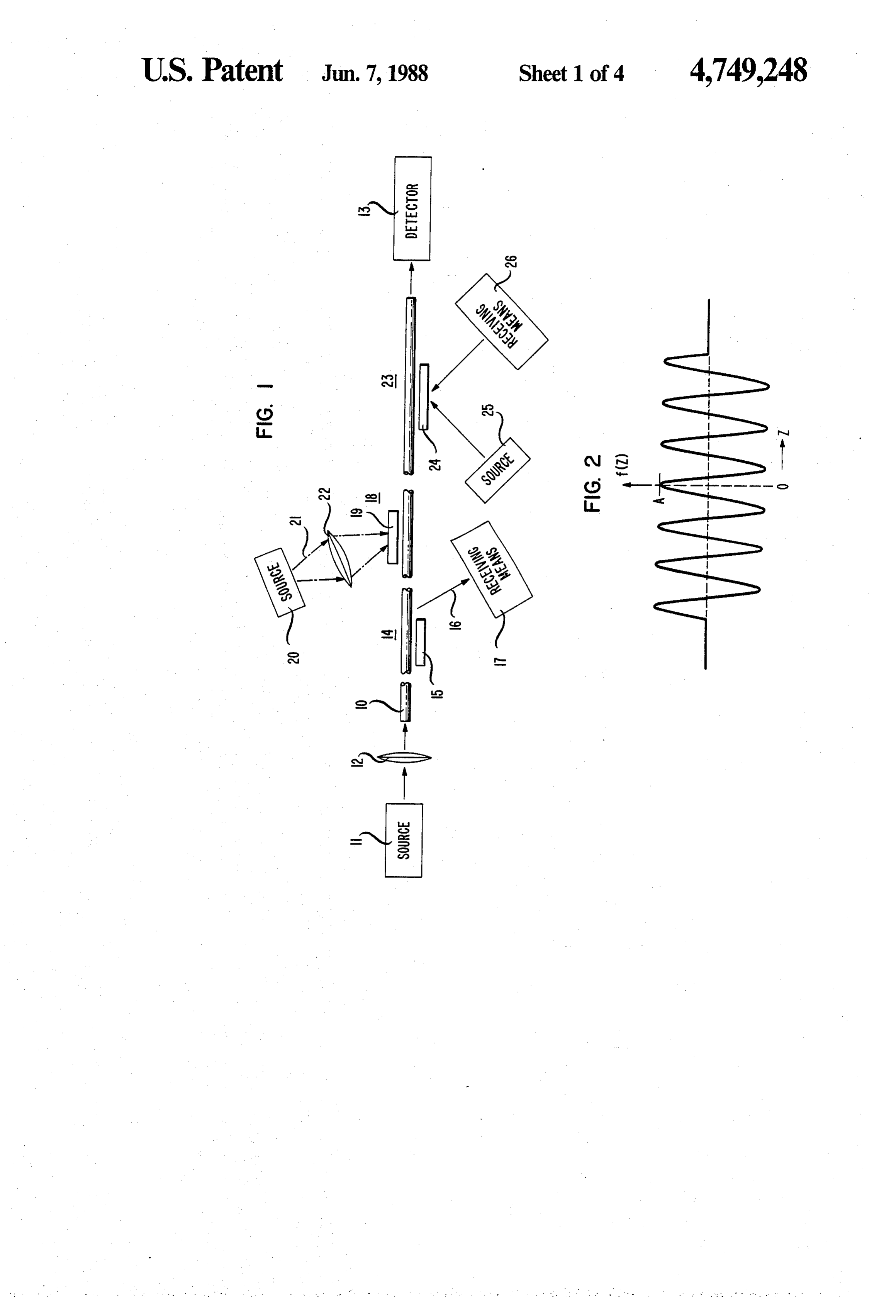
communications system comprising means for injection Many currently used single mode fiber designs are and extraction of optical power at intermediate fiber 5 such that, at the design wavelength A of the fiber, the regions; lowest order TL mode (LP) has a relatively small FIG. 2 depicts schematically the axis of an optical attenuation constant a 11, such that the above discussed fiber with periodic distortions that form a "grating' limitation generally can be met at least for LP11, and constant amplitude; typically also for other TL modes. FIG. 3 is a plot of the Fourier transform of the grat O As previously discussed, mode coupling is produced ing function f(z)= A cos(2Z, (-7tn/O).<z<(at N/2); by means of a "grating' introduced into the fiber at or FIG. 4 is a plot of the grating function f(z)= g(z) near the location where optical power is to be injected cos(2Z, for the same range of z as in FIG. 3, where into, or removed from, the fiber core. The TL mode g(z)= exp(-z/a2); LPs to which LPo1 couples most strongly is selected by FIG. 5 depicts the Fourier transform of the function 15 appropriate choice of grating parameters, principally of shown in FIG. 4;
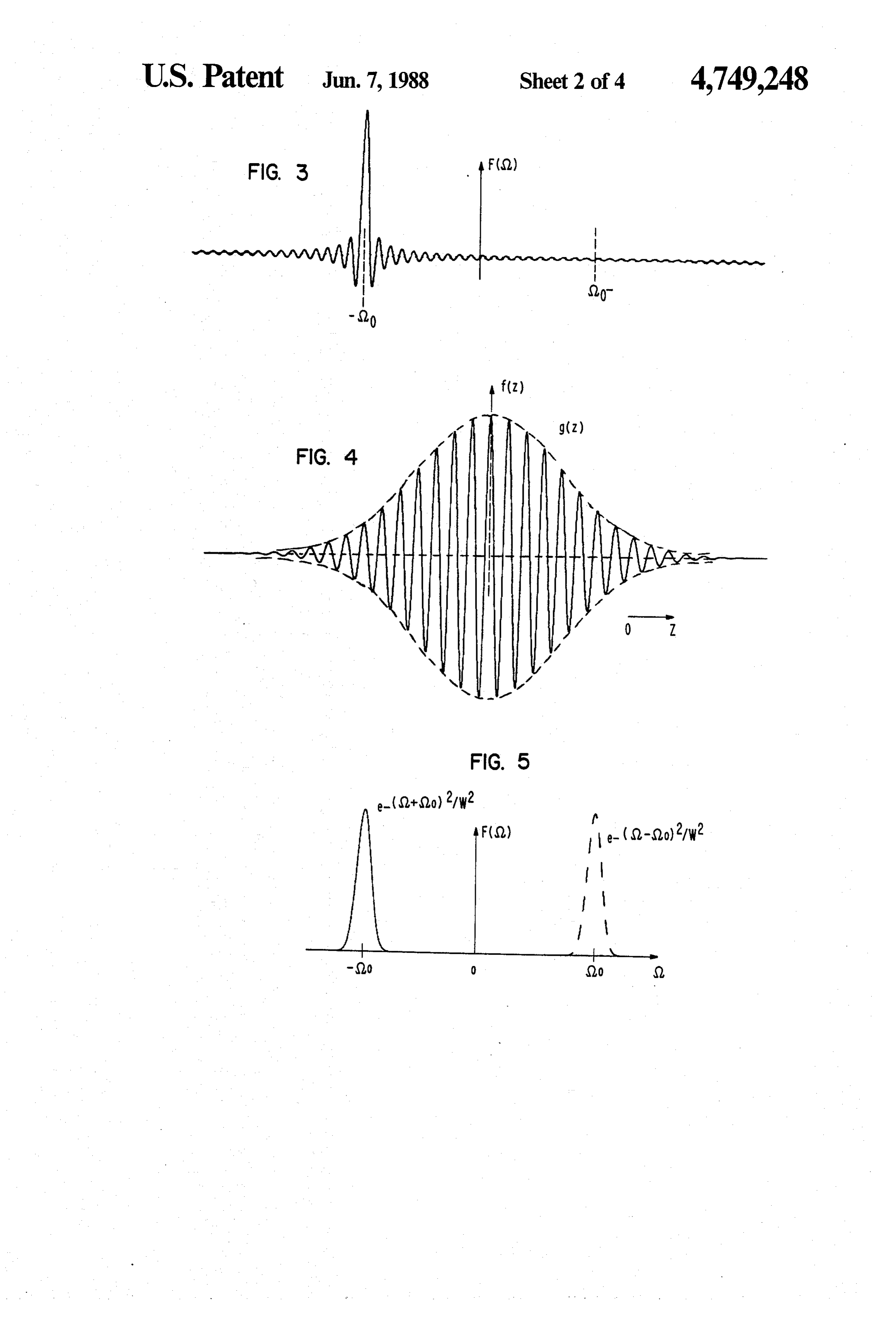
FIG. 6 shows the radiation pattern of an exemplary the repeat distance A(z) for a given wavelength. By choosing A(z) such that (2=(2/A) > 301-(27t/A)ncil semiconductor laser and the acceptance function of an one insures that LPo1 couples to one (or more) TL exemplary single mode fiber;
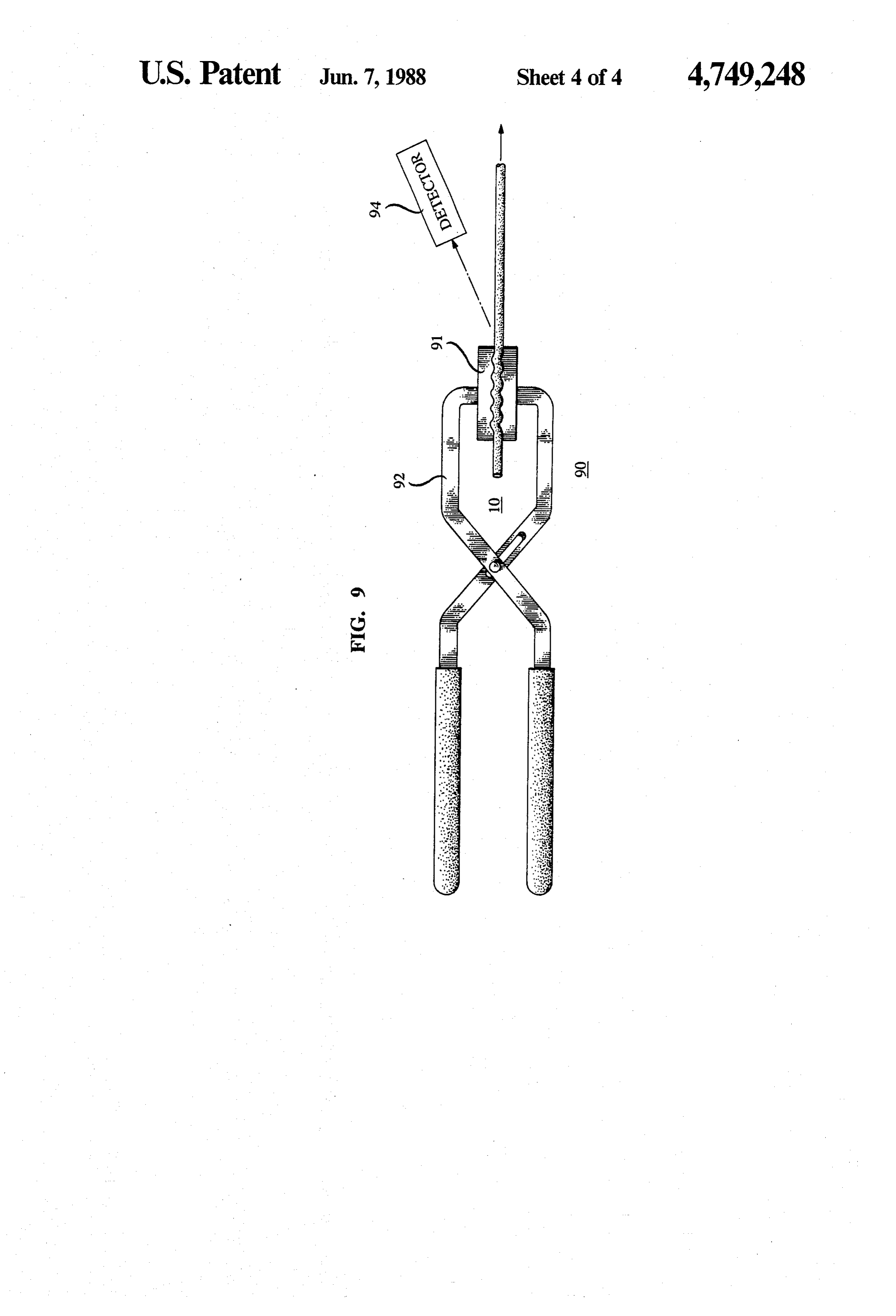
FIG. 7 schematically shows an exemplary communi 20 modes. By furthermore choosing A(z) such that Oo-f301-6s the grating causes quasi-resonant cou cations system comprising a photorefractive modulator; pling principally between LPo1 and LP, if NAa FIG.8 schematically depicts a photorefractive modu s<<1. An exemplary value for A is of the order of 500 lator FIG. 9 schematically shows aspects of an inven pum. Typically, the grating repeat distance in single tive communications system; and 25 mode fiber is less than about 1 mm, which is to be con
DETALED DESCRIPTION trasted with the situation in multimode fiber, where the FIG. 1 schematically depicts an exemplary communi repeat distance typically is greater than 1 mm. cations system according to the invention, in which 10 For realistic gratings in typical single mode fiber, the is a length of optical fiber, 11 a source of electromag resonance
is of finite width. By this is meant that, for coupling occurs not only between LPo1 netic radiation, e.g., a laser emitting at 1.55 m, 12 30 means for coupling the radiation into an end of the fiber, and LPs, but also, albeit weaker, between the former and TL modes LP whose propagation constant is close and 13 is a radiation detector. Intermediate locations 14, 18, and 23 are sites at which coupling means according to 9. In particular, for an N-element grating one can to the invention are deployed, with 15 being means for show that a measure of the resonant coupling width is tapping radiation 16 from the fiber, 19 being means for 35 2N-, i.e., resonance coupling will occur to modes injecting radiation 21 into the fiber, and 24 being means LPThe if As-gi <0N.
required repeat distance for a given fiber can for both tapping and injecting of radiation. Receiving either be determined by computing the propagation means 17 and 26 can be any means for receiving the tapped radiation, e.g., a detector, or another fiber. Simi constants for the relevant modes by known methods, or larly, sources 20 and 25 can be any source of radiation it can be determined experimentally. Frequently, it will to be injected, e.g., a laser, a LED, or another fiber. be found advantageous to use a combination of the two Although means 22 for changing the shape of the radia approaches. As is well known, the value of the propaga tion pattern are shown at only one coupling site, it is tion.constant of a given mode depends not only on the clear that such means can, but need not be, used gener wavelength of the radiation but also on fiber parame ally. 45 ters, including effective refractive index and index pro A central aspect of the instant invention is the discov file shape.
ery that it is possible to achieve essentially resonant In order to characterize a grating, it is not only neces coupling between the propagating mode LPo1 and TL sary to specify the repeat distance but also further pa modes, principally LP11, in single mode optical fiber. rameters, including the envelope function. For instance, This discovery, which is not predicted by currently 50 for a grating formed by spatially periodic distortions of accepted theory, makes possible the construction of the fiber, the envelope function specifies the amplitudes very efficient means for coupling radiation from, and of the distortions impressed on the fiber axis. For a /or into, single mode optical fiberat intermediate points grating formed by spatially periodic variations of the along the fiber, without having to break or terminate refractive index of the fiber, the envelope function typi the fiber. 55 cally specifies the maximum refractive index of the If the loss of optical power from a TL mode in a fiber various grating elements.
length of the order of a centimeter is only a small frac In a simple exemplary case, the grating is sinusoidal, tion of the power in the mode, then the radiation mode i.e., it can be described by a function f(z)= A cosz, acts locally essentially as if it were a bound mode. That for (- TN/O).<z<(TN/(2), and zero otherwise. The is to say, if the quantity NAois C C 1 for the TL mode coordinate origin has been selected such that the grat LPs then the power transfer between LPo1 and LPs can ing is symmetrical about the coordinate origin. This is be essentially resonant. Under these circumstances, done for the sake of convenience only, and has no fun coupling conditions (e.g., grating spacing A(z), number damental significance.
of elements N, and amplitude of the envelope function This function is depicted in FIG. 2, with greatly g(z)) can be found such that the radiation can be effi 65 exaggerated ordinate. In the above exemplary case the ciently coupled into, or from, a single mode optical envelope function is a constant (A) independent of z. In fiber. Although useful coupling may also be possible if general, however, the envelope function can be a func the LPs mode attenuation constant is greater than about tion of z, and, as will be discussed next, gratings with
Page 9
nonconstant envelope can advantageously be used in tween these sources and a coupler of Gaussian ampli devices according to the invention. tude.
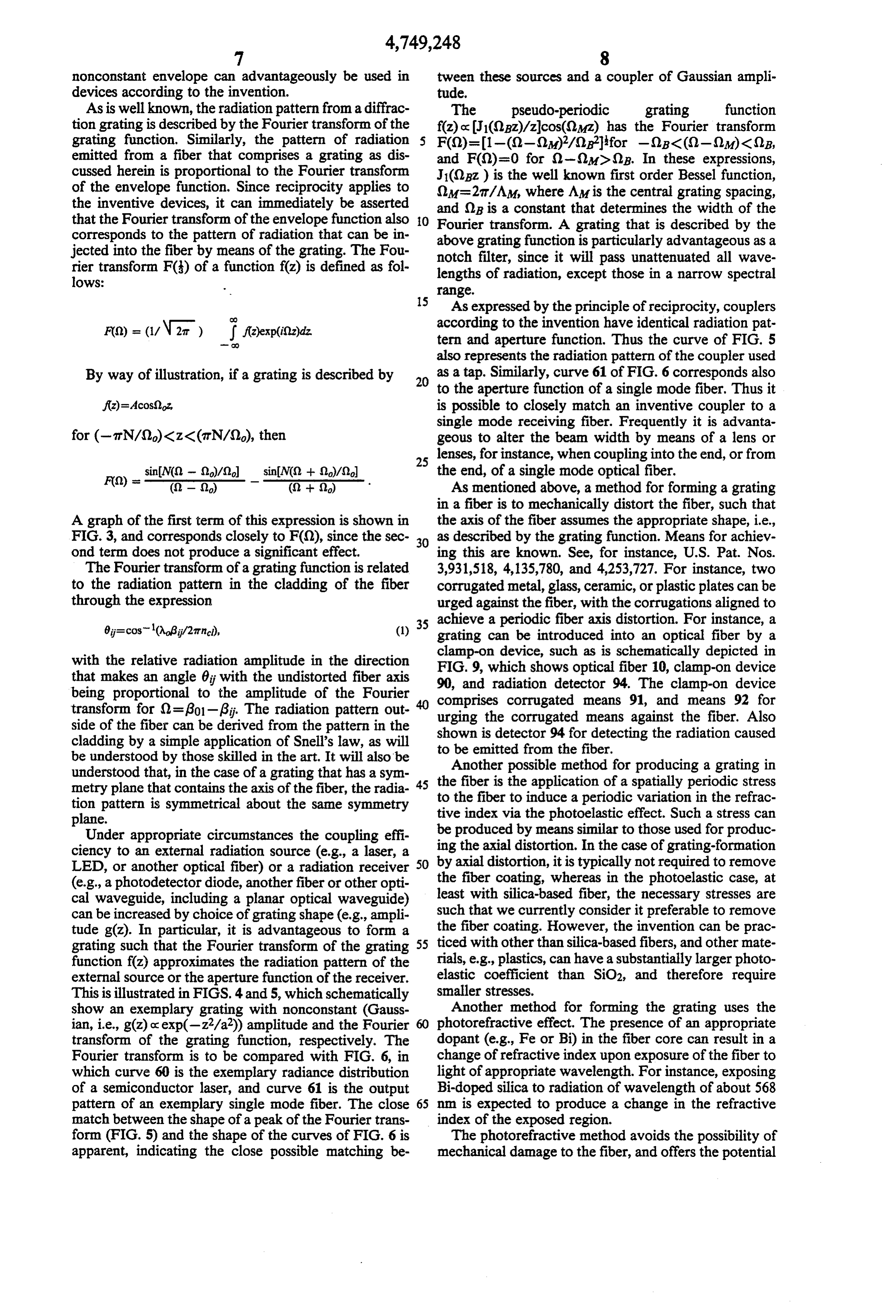
As is well known, the radiation pattern from a diffrac The pseudo-periodic grating function tion grating is described by the Fourier transform of the f(z) oc1(2pz)/zcos(2Mz) has the Fourier transform grating function. Similarly, the pattern of radiation F(0)=1-((2-2)/Offor -0BC(S)-(2M) < 2B, emitted from a fiber that comprises a grating as dis and F(0)=0 for )-(2M)(2B. In these expressions, cussed herein is proportional to the Fourier transform J1(OBz) is the well known first order Bessel function, of the envelope function. Since reciprocity applies to (M=27T/AM, where AM is the central grating spacing, the inventive devices, it can immediately be asserted and () is a constant that determines the width of the that the Fourier transform of the envelope function also O Fourier transform. A grating that is described by the corresponds to the pattern of radiation that can be in above grating function is particularly advantageous as a jected into the fiber by means of the grating. The Fou notch filter, since it will pass unattenuated all wave rier transform F(s) of a function f(z) is defined as fol lengths of radiation, except those in a narrow spectral lows: range.
15 As expressed by the principle of reciprocity, couplers according to the invention have identical radiation pat tern and aperture function. Thus the curve of FIG. 5 also represents the radiation pattern of the coupler used
By way of illustration, if a grating is described by as a tap. Similarly, curve 61 of FIG. 6 corresponds also to the aperture function of a single mode fiber. Thus it f(z)=Acos(22, is possible to closely match an inventive coupler to a single mode receiving fiber. Frequently it is advanta for (-arN/(2)<z<(TN/S2), then geous to alter the beam width by means of a lens or 25 lenses, for instance, when coupling into the end, or from sin() - (2)/2 sinM(2 + 2)/2) the end, of a single mode optical fiber.
Fo) = - in a (2 - 2) As mentioned above, a method for forming a grating in a fiber is to mechanically distort the fiber, such that
A graph of the first term of this expression is shown in the axis of the fiber assumes the appropriate shape, i.e., FIG. 3, and corresponds closely to F(0), since the sec 30 as described by the grating function. Means for achiev ond term does not produce a significant effect. ing this are known. See, for instance, U.S. Pat. Nos. The Fourier transform of a grating function is related 3,931,518, 4,135,780, and 4,253,727. For instance, two to the radiation pattern in the cladding of the fiber corrugated metal, glass, ceramic, or plastic plates can be through the expression urged against the fiber, with the corrugations aligned to 6=cos(Aagj/27tnci), (1) 35 achieve a periodic fiber axis distortion. For instance, a grating can be introduced into an optical fiber by a clamp-on device, such as is schematically depicted in with the relative radiation amplitude in the direction FIG. 9, which shows optical fiber 10, clamp-on device that makes an angle 0 with the undistorted fiber axis being proportional to the amplitude of the Fourier 90, and radiation detector 94. The clamp-on device transform for Q = go1-6. The radiation pattern out urging the corrugated
side of the fiber can be derived from the pattern in the shown is detector 94 formeans corrugated against the fiber. Also detecting the radiation caused cladding by a simple application of Snell's law, as will be understood by those skilled in the art. It will also be to Another be emitted from the fiber.
possible method for producing a grating in understood that, in the case of a grating that has a sym 45 the fiber is the application of a spatially periodic stress metry plane that contains the axis of the fiber, the radia to the fiber to induce a periodic variation in the refrac tion pattern is symmetrical about the same symmetry tive index via the photoelastic effect. Such a stress can plane.
Under appropriate circumstances the coupling effi be ing produced by means similar to those used for produc the axial distortion. In the case of grating-formation ciency to an external radiation source (e.g., a laser, a 50 by axial
LED, or another optical fiber) or a radiation receiver the fiberdistortion, coating, it is typically not required to remove whereas in the photoelastic case, at (e.g., a photodetector diode, another fiber or other opti cal waveguide, including a planar optical waveguide) least with silica-based fiber, the necessary stresses are can be increased by choice of grating shape (e.g., ampli such that we currently consider it preferable to remove tude g(z). In particular, it is advantageous to form a the fiber coating. However, the invention can be prac grating such that the Fourier transform of the grating 55 ticed with other than silica-based fibers, and other mate function f(z) approximates the radiation pattern of the rials, e.g., plastics, can have a substantially larger photo external source or the aperture function of the receiver. elastic coefficient than SiO2, and therefore require This is illustrated in FIGS. 4 and 5, which schematically smaller stresses.
show an exemplary grating with nonconstant (Gauss Another method for forming the grating uses the ian, i.e., g(z) oc exp(-z2/a2)) amplitude and the Fourier photorefractive effect. The presence of an appropriate transform of the grating function, respectively. The dopant (e.g., Fe or Bi) in the fiber core can result in a Fourier transform is to be compared with FIG. 6, in change of refractive index upon exposure of the fiber to which curve 60 is the exemplary radiance distribution light of appropriate wavelength. For instance, exposing of a semiconductor laser, and curve 61 is the output Bi-doped silica to radiation of wavelength of about 568 pattern of an exemplary single mode fiber. The close 65 nn is expected to produce a change in the refractive match between the shape of a peak of the Fourier trans index of the exposed region.
form (FIG. 5) and the shape of the curves of FIG. 6 is The photorefractive method avoids the possibility of apparent, indicating the close possible matching be mechanical damage to the fiber, and offers the potential
Page 10
for forming a grating with time-dependent parameters. gratings can be designed to have substantially no attenu Such a grating can be used to modulate the amplitude of ation for radiation outside a well-defined wavelength radiation guided in the fiber, by time-dependent re range. However, it is also possible to achieve effective moval of radiation from the fiber. Such a device can be filtering with periodic, even constant amplitude, grat used, for instance, on customer premises, to provide ings. For instance, we have achieved 15 dB excess at economical means for modulating an inexpensive cw tenuation at 1.5 m, with 0.02 dB excess attenuation at light source. A portion of an exemplary communica 1.3 un, with a constant amplitude (N = 60, A=560 um) tions system incorporating such devices is schematically axial distortion grating.
depicted in FIG. 7, wherein 70 corresponds to a tele In some circumstances, it may be desirable to provide phone central office or other major switching center 10 means for enhancing the radiation of TL modes from connected by trunk lines 71 to other similar centers. the cladding of the single mode fiber. This can be Multiplexed optical pulses are transmitted over optical achieved, for instance, by contacting the fiber with an fiberlines 72 from and to local distribution points 73, of appropriate dielectric body at a downstream location, which only one is shown. Signals arriving in 73 from 72 or by producing a macrobend in the fiber downstream are demultiplexed and distributed to subscriber lines 74 15 from the grating. Such means are known in the art. See, and transmitted to subscriber stations 75 (only one is for instance, U.S. Pat. Nos. 3,931,518 and 4,135,780. shown). The subscriber apparatus typically would com Furthermore, it may be advantageous to use a corru prise a directional coupler 76 if 74 is used as a two-way gated body not only to produce the grating but also to transmission path. However, no such coupler may be perform an optical function, e.g., to change the shape of necessary if 74 is a duplex line. In either case, signals the emitted radiation pattern. Such corrugated transpar arriving in 75 are detected by detector 77, whose output ent dielectric bodies are known (see, U.S. Pat. No. 78 is available for processing by known means. The 4,253,727).
station apparatus also comprises a cw light source 81 (e.g., an LED, or a wide band source such as an incan EXAMPLE descent source together with appropriate narrow band 25 In commercially available single mode optical fiber ing means, e.g., a filter), the output of 81 being coupled (8.5 um core diameter, 125 um fiber diameter, dual into a fiber comprising photorefractive modulator 80.
The modulator is responsive to input signal 79, i.e., the polymer coating, diameter of coated fiber 245 um, cut amount of radiation transmitted through 80 and thence by squeezing anof off wavelength LP11~ 1.27m) a grating was formed intermediate portion of the coated fiber coupled into 74 varies in response to 79. The modulated between two corrugated PMMA
cw signal arriving in 73 from 75 typically would be bers were aligned such that valleysmembers. in one The mem member were transformed into a standard pulsed signal and then be opposite peaks in the other member. Each corrugation switched onto line 72 or onto another line 76. It will be understood that the depicted network is exemplary had 10 periods, with a spacing of about 559 um. A only, and that subscriber stations as described can be resultingforce 35 normal of about 15 N was applied to the members, in a deformation amplitude of about 0.2 m. A used with any fiber network geometry.
FIG. 8 schematically depicts an exemplary photore commercially available 1.3 um laser source was butt fractive modulator 80. The modulator comprises means coupled to one end of this optical fiber (to be referred to for exposing a region of fiber 87 to spatially and tempo as the first fiber), the length of the transmission path rally varying radiation. The means comprise a radiation 40 between source and grating being about 1 km. A com source 82 whose output intensity is responsive to signal mercially available radiation detector was butt-coupled 79, and means 84 (e.g., a diffraction grating) for trans to a short length of single mode optical fiber of the forming output 83 of 82 into spatially varying radiation, above-described type (to be referred to as the second with N maxima 851, 852, ... 85N. The core of fiber 87 fiber), and the other end of the second fiber was placed contains an appropriate dopant (e.g., Bi), and radiation 45 at the focus of a graded index cylindrical lens of 2 mm 83 is chosen to have a wavelength that causes the dop diameter, with a normalized refractive index difference ant to undergo a transition which results in a change of of about 0.04. The first fiber was mounted on a gonion the refractive index of the fiber core. The transformed eter stage such that the center of the grating region was state advantageously has a relatively shortlifetime, such at the center of the circular measurement track along that modulation bandwidths of the order of 1 MHz can 50 which amounting platform could be moved. The lensed be achieved. The length of fiber 87 is coupled to con second optical fiber was attached to the platform, and ventional optical fiber (multimode or single mode) 10 the power of the laser radiation that was emitted from and 10' by means of connectors 86, with cw radiation the first fiber and coupled into the second fiber was being introduced into 10'. If 83 is modulated temporally, determined as a function of the angle 6 between the axis then a temporally varying grating is formed in 87, caus 55 of the first fiber and the optical axis of the lensed second ing coupling of a time-varying amount of radiation 88 fiber. The maximum of detected power was about 18.5 from 87, and consequently amplitude modulation of the dB below the power coupled into the first fiber, and radiation in the fiber. For information on the photore occurred for 6-20.
fractive effect see, for instance, A. M. Glass, Optical EXAMPLE 2
One of the advantages of the instant invention is that in a set-up substantially as described above (except grating creation by axial distortion requires only such that detector and laser source were interchanged), the small deformations (typically <0.5um) that fiber dam power that was emitted from the lensed second fiber age (including damage to the coating) is essentially and coupled into the first fiber by means of the grating nonexistent. Thus, it is possible to attach such couplers 65 was determined. The maximum detected power was to fiber for indefinite periods of time. about 18 dB below the power coupled into the second Pseudo-periodic inventive couplers may be particu fiber, and occurred for 6-20. The small difference larly advantageous for filtering applications, since such between the powers observed in Examples 1 and 2 is
Page 11
due to the variation in the efficiency of the connectors tive index of the fiber core can be changed by means of attached to source and detector, respectively. the photo-elastic effect.
As will be readily appreciated by those skilled in the 6. The coupling means of claim 2, further comprising art, the repeat distance A(z) and amplitude function g(z) means for enhancing the emission of radiation from the that are associated with a grating are nominal mathe cladding of the fiber.
matical expressions, and that the actual repeat distance 7. The coupling means of claim 6, wherein the means and amplitude of a grating in a fiber may depart from for enhancing emission of radiation from the cladding the nominal value, due to unavoidable manufacturing comprise a dielectric body contacting the fiber down imperfections. However, typically it will be possible for stream from the grating, the dielectric body being sub actual repeat distances and amplitudes to be within 10 stantially transparent for the radiation of wavelength No. -10%, preferably 5%, of their nominal values. 8. The coupling means of claim 1, wherein the LPs It will also be appreciated that, although in principle mode is the LP11 mode.
N, the number of elements in a grating, can be any 9. The coupling means of claim 1, wherein the nomi integer greater than 1, typically N will be at least 5, nal amplitude function g(z) is a constant. frequently 10 or more. 15 10. The coupling means of claim 1, wherein the nomi
What is claimed is: nal amplitude function g(z) is proportional to a Gauss 1. Means for coupling electromagnetic radiation of ian function of Z.
wavelength A into or from an intermediate portion of an optical fiber, the fiber comprising a core and a clad nal11.repeatThe coupling means of claim 1, wherein the nomi ding surrounding the core and having optical character 20 12. The distance coupling
A(z) is a constant.
means of claim 1, wherein at least istics including an attenuation constant aij and a propa the intermediate portion gation constant 6 for each mode LP of the radiation material that is substantiallyof transparent the fiber is coated with a that can be present in the fiber, where iis a non-negative magnetic radiation of wavelength No. for the electro integer and j is a positive integer, 13. The coupling means of claim 1, wherein the
means adapted for forming a grating comprise means (a) the fiber is a single mode optical fiber at the wave for length Ao; locally changing the core refractive index. (b) the coupling means comprise means adapted for source 14. An optical communications system comprising a forming in the intermediate portion of the fiber a of first electromagnetic radiation of wavelength grating consisting of N elements, a grating being a 30 Ao, an optical fiber adapted for guiding the first radia portion offiberin which one or more fiber parame tion, first means for coupling the first radiation into the ters are caused to vary as a function of the axial fiber at a first fiber location, and means for detecting, at coordinate z of the fiber, the fiber parameters in a second fiber location spaced apart from the first fiber cluding the core refractive index and the fiber axis location, the first radiation that is transmitted from the geometry, associated with the grating being a nom 35 first to the second fiber location through the fiber, the inal repeat distance A(z) and a nominal amplitude fiber comprising a core and a cladding surrounding the function g(z); core, the fiber having optical characteristics including (c) A(z) is chosen such that an attenuation constant aij and a propagation constant (2=(27T/A)>{301-2arncl/No, where A is the aver By for each mode LP of the first radiation that can be age repeat spacing in the grating, Bol is the propa present in the fiber, where i is a non-negative integer gation constant of the LPol mode of radiation, and and j is a positive integer, the optical communications nel is the refractive index of the cladding of the system further comprising second means for coupling fiber; m first radiation into or from the fiber at a third fiber (d) A(z) furthermore is chosen such that location intermediate the first and the second fiber loca: Oo-go1-3s, where 3s is the propagation con 45 tions without breaking or terminating the fiber, stant of the LPs mode of radiation, where LPs is a characterized in that tunneling leaky (TL) mode of the radiation of (a) the fiber is a single mode optical fiber at the wave wavelength A in the fiber; and length No, (e) the attenuation constant as of the LPs mode is less (b) the second means comprise means adapted for than about 1 dB/cm. 50 forming in the intermediate portion of the fiber a 2. The coupling means of claim 1, wherein the means grating consisting of N elements, a grating being a adapted for forming a grating comprise means adapted portion offiber in which one or more fiber parame for impressing an undulation upon the fiber axis. ters have a regular variation as a function of the 3. The coupling means of claim 2, wherein the means axial coordinate z of the fiber, the fiber parameters for impressing an undulation upon the fiber axis com 55 including the core refractive index and the fiber prise at least one corrugated body, and means for urging axis geometry, associated with the grating being a the corrugated body against the fiber. nominal repeat distance A(z) and a nominal ampli 4. The coupling means of claim 1, wherein the means tude function g(z);
for locally changing the core refractive index comprise (c) A(z) is chosen such that ()a=27t/A>go1-27tncl. a photo-refractively active chemical element present in /No, where A is the average repeat spacing in the the core, and means for exposing the fiber core to ac grating, 601 is the propagation constant of the LPol tinic radiation, whereby the refractive index of the fiber mode of radiation, and inci is the refractive index of core can be changed by means of the photo-refractive the cladding of the fiber; effect. (d) A(z) furthermore is chosen such that 5. The coupling means of claim 1, wherein the means 65 2- go1-9, where 6s is the propagation con for locally changing the core refractive index comprise stant of the LPs mode of radiation, and where LPs at least one corrugated body, and means for urging the is a tunneling leaky (TL) mode of the radiation of corrugated body against the fiber, whereby the refrac wavelength Aoin the fiber; and
Page 12
(e) the attenuation constant as of the LPs mode is less the fiber, and means for detecting the first radiation emitted from the fiber at the third fiber location.
than about 1 dB/cm. 17. Communications system of claim 14, wherein the 15. Communications system of claim 14, wherein the source of electromagnetic radiation also emits electro 5 magnetic radiation of wavelength other than A, second means form a variable attenuator.
wherein the first means are adapted for coupling at least 16. Communications system of claim 14, wherein the some of the radiation of wavelength other than A into second means comprise clamp-on means comprising the fiber at the first fiber location, and wherein the second means form a filter adapted for selectively cou corrugated means adapted for forming the grating in the 10 pling at least some of the first radiation from the fiber. fiber, means for urging the corrugated means against is
Provenance
- Collection
- Cited prior art
- Original PDF
- patentimages.storage.googleapis.com →
- Filed
- 1985-11-06
- Pages
- 12
- Method
- pdftotext (the PDF's own text layer) + pdftoppm 300dpi page scans
- Source
- Google Patents bibliographic record
- Granted
- 1988-06-07
- Inventors
- James A. Aberson, Jr.; Ian A. White; AT&T Bell Laboratories Inc
- Transcribed from
- patentimages.storage.googleapis.com →