patent · US5082544
Apparatus for gas generation
21 January 1992
Page 1 — bibliographic record
HHHHHHHHHHHHH
United States Patent (19) 11) Patent Number: 5,082,544 Willey et al. 45 Date of Patent: Jan. 21, 1992 54 APPARATUS FOR GAS GENERATION 4,206,029 6/1980 Spirig .............................. 204/274 X 4,317,709 3/1982 Ichisaka et al. . ... 204/274X 75 Inventors: Alan P. Willey; Neal T. Radford, both 4,336,122 6/1982 Spirig .............. ... 204/274 X of Metro Manila, Philippines 4,344,831 8/1982 Weber ...... ... 204/274 X 4,361,474 11/1982 Shoaf et al. ..................... 204/274 X 73 Assignee: Command International, Inc., Hong
Kong Primary Examiner-Donald R. Valentine (21) Appl. No.: 473,668 Attorney, Agent, or Firm-Townsend and Townsend
An electrolytic gas generating apparatus for producing 30 Foreign Application Priority Data a combustible mixture of hydrogen and oxygen by elec Nov. 17, 1989 (GB) United Kingdom ................. 8926.096 trolysis of water is disclosed, for particular use in a gas 511 Int. Cl. ........................ C25B 9/00; C25B 11/02; welding apparatus. The generating apparatus comprises C25B 15/08 a d.c. power supply 100 connected to electrolytic cells 52 U.S. C. .................................... 204/270; 204/272; 200, a dehumidifier 400 for scrubbing the gas mixture 204/278; 204/279 generated by the cells 200, a gas regulator 500, a modi 58. Field of Search ............... 204/256, 258, 262, 266, fier 600 which modifies the combustion characteristics 204/270, 272, 278, 277,279, 269 of the gas and a flash arrester 660. Gas generation is
controlled by a main control board 800 in accordance with sensors which measure parameters to calculate
820, 13 5/1906 Hinkson .......................... 204/269 X dance with demand.
3,507,770 4/i970 Fleming .............................. 204/272 3,990,962 11/1976 Götz ............................... 204/272 X 6 Claims, 9 Drawing Sheets
AAASS
Page 2
Drawing sheet — no readable text.
Page 3
Drawing sheet — no readable text.
Page 4
Drawing sheet — no readable text.
Page 5
Drawing sheet — no readable text.
Page 6
Drawing sheet — no readable text.
Page 7
Drawing sheet — no readable text.
Page 8
Drawing sheet — no readable text.
Page 9
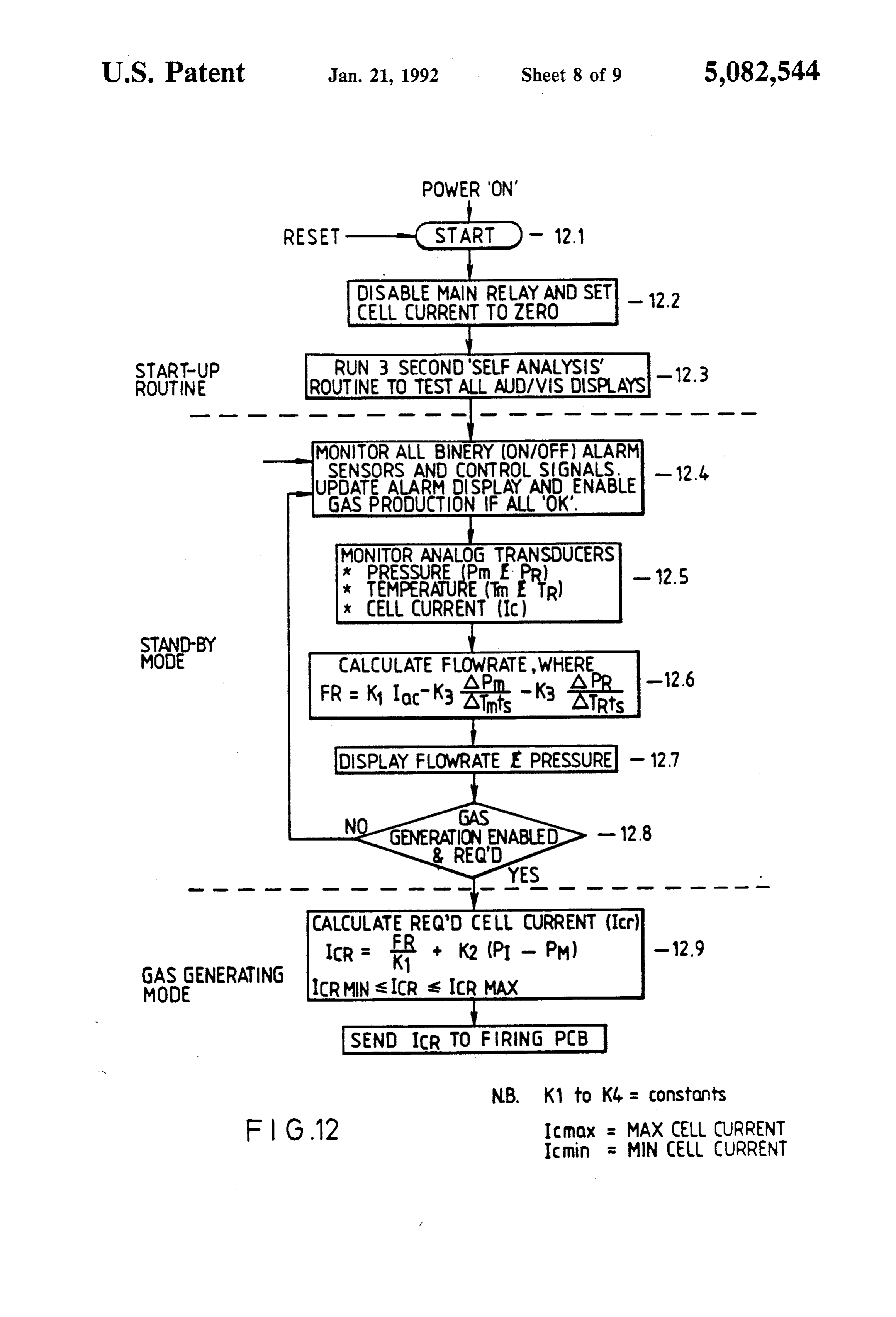
POWER 'ON'
DISABEMAN RELAY AND SET
CELL CURRENT TO ZERO
ROUTINE RUN-3TOSE9NDSEANASIS-12.3
ROUTINE TEST ALL AUD/VIS DSPLAYS ''
MONITOR ALL BINERY CON/OFF) ALARM
SENSORS AND CONTROLSGNALS-124.
UPDATEAABMRSPLAYANDENABLE
GAS PRODUCTION FALL'OK'.
MONITOR ANALOG TRANSDUCERS
* PRESSURE (Prn EPR)
ESSEER
x CELL CURRENT (IC)
MODE CALCULATE FLOWRATE
WHERE
DISPLAY FLOWRATE E PRESSURE - 127
CALCULATE REGO CELL CURRENT (cr)
GAS GENERATING
MODE ICRMN slicR s ICR MAX
SEND ICR TO FRING PCB
N.B. K1 to K4 = COnStants
F G12 IC mox = MAX CELL CURRENT Imin = MIN CELL CURRENT
Page 10
Drawing sheet — no readable text.
Page 11
mixing a second combustible gas with the first combus
APPARATUS FOR GAS GENERATION tible gas and further comprising bypass means for by passing the combining means and regulating means for
FIELD OF THE INVENTION controlling the by-pass means.
This invention relates to apparatus for gas generation Preferably the first combustible gas is arranged to be particularly but not exclusively for use in welding appa bubbled through a volatile combustible liquid, the sec attS. ond gas thus becoming entrained with the first gas. Preferably the first gas is a hydrogen/oxygen mixture
BACKGROUND OF THE INVENTION and the second gas is a volatized hydrocarbon. Devices which generate hydrogen and oxygen gases 10 According to the invention in a fourth aspect, there is provided apparatus for modifying the combustion char by electrolysis of water for use as a combustible mixture in gas welding apparatus have been proposed. Such acteristics of a gas, the apparatus comprising a vessel for devices, in general concept, have the advantage over a combustible fluid in liquid form and means for bub conventional gas welding equipment that storage of bling a combustible gas through the liquid, said means dangerous bottled gases such as acetelyene or LPG is 15 comprising a diffuser.
not required. The formation of a combustible mixture Preferably the diffuser comprises a manifold having a by electrolysis of water is also potentially inexpensive plurality of spaced gas outlets. and the product of combustion of the gas mixture, being The manifold may be in the form of an inverted tray, water, is not harmful. the gas outlets being spaced around the periphery of the However, previous attempts at designs of such de-20 tray.
vices have not proved to be commercially successful According to the invention in a fifth aspect, there is due to high manufacturing cost and poor gas producing provided a method of measuring the gas flowrate from efficiency. an electrolytic cell of an electrolytic gas generator com It is an object of the invention to provide an im prising the steps of measuring the current (IC) supplied proved gas generating apparatus. 25 to the cell, the cell temperature (TM) and cell pressure SUMMARY OF THE INVENTION (PM) and calculating the flowrate in accordance with the following equation:
According to the invention in a first aspect, there is provided an end cap for an electrolytic gas generation Flowrate=K1.IC-K2(APM/(ATM.ts)) cell including a plurality of nested electrode tubes, the 30 end cap having means for locating the tubes in spaced Where relation and a plurality of openings interconnecting the ATM is the change in cell temperature regions between the tubes. APM is the change in cell pressure In a first preferred form, the openings between adja K1, K2 are constants cent pairs of regions are offset relative to one another 35 ts= sampling rate and preferably are opposed to one another.
An end cap of this construction find particular appli gasIfmay the generator comprises a further vessel in which become stored, the flowrate may be calculated cation as a bottom end cap of a vertically arranged in accordance with the following equation: electrolytic cell, the end cap providing inter-connection paths for the electrolyte disposed between the tubes 40 Modified while minimising the by-pass current across the tubes. flowrates K
In a second preferred form, the locating means com 1XIC-K2(APM/(ATM.ts)-K3(APR/(ATR.ts)- prises a plurality of lands, the openings being formed ).
between the lands. An end cap of this construction find particular application as a top end cap of a vertically 45 Where ATR is the change in temperature in the further arranged cell. The openings allowed convenient exit vessel parts for the gas from the cell. The lands serve to space APR is the change in pressure in the further vessel the tubes from the openings so that, when filled with K, K2, K3: Constants gas, a substantial by-pass current across the top of the
The locating means preferably locates the nested The invention further provides a method of control tubes concentrically. ling the gas generated by controlling the input current According to the invention in a second aspect, there to give a required flowrate, the flowrate being calcu is provided gas generation apparatus comprising an lated in accordance with the fifth aspect of the inven electrolytic cell and a demister for demisting gas gener- 55 tion.
ated by the cell, the cell and demister using the same Furthermore, the invention provides apparatus for working liquid and the cell being connected to the de calculating the gas flowrate in an electrolytic gas gener mister whereby liquid from the demister is able to be ator having at least one cell, the apparatus comprising supplied to the cell. means for measuring the input current to the cell, means Preferably the working liquid supplied to the demis- 60 for measuring the cell temperature, means for measur ter is dionized water and the cell uses a metal hydroxide ing the cell pressure and processing means for calculat dissolved in water as an electrolyte. Dehumidification ing the flowrate in accordance with the fifth aspect of of the gas results in entrained hydroxide being dissolved the invention.
by the deionized water, this weak hydroxide solution According to the invention in a sixth aspect there is then being supplied to the cell on demand. 65 provided an electrolytic gas generator comprising a gas According to the invention in a third aspect there is generation cell having a plurality of electrodes for re provided gas generation apparatus comprising means ceiving a working liquid therebetween, gas condition for generating a first combustible gas and means for ing means connected to the cell for removing working
Page 12
liquid vapour entrained in gas generated by the cell; and DETAILED DESCRIPTION OF THE means for matching the working liquid removing ca PREFERRED EMBOEDIMENT pacity of the gas conditioning means to the operation of the cell, the matching means comprising temperature With reference to the figures, an embodiment of gas control means for controlling the temperature of the 5 generating apparatus according to the invention is working liquid in the cell. shown, applied to a gas welding system. In general Preferably the temperature is controlled to be less terms, the device produces a combustible mixture of than 75 C., in the range 55 C.-75° C. and substantially hydrogen and oxygen by electrolysis of water, which is 65 C. processed to provide a suitable gas mixture for use with According to the invention in a seventh aspect, there 10 a gas welding torch.
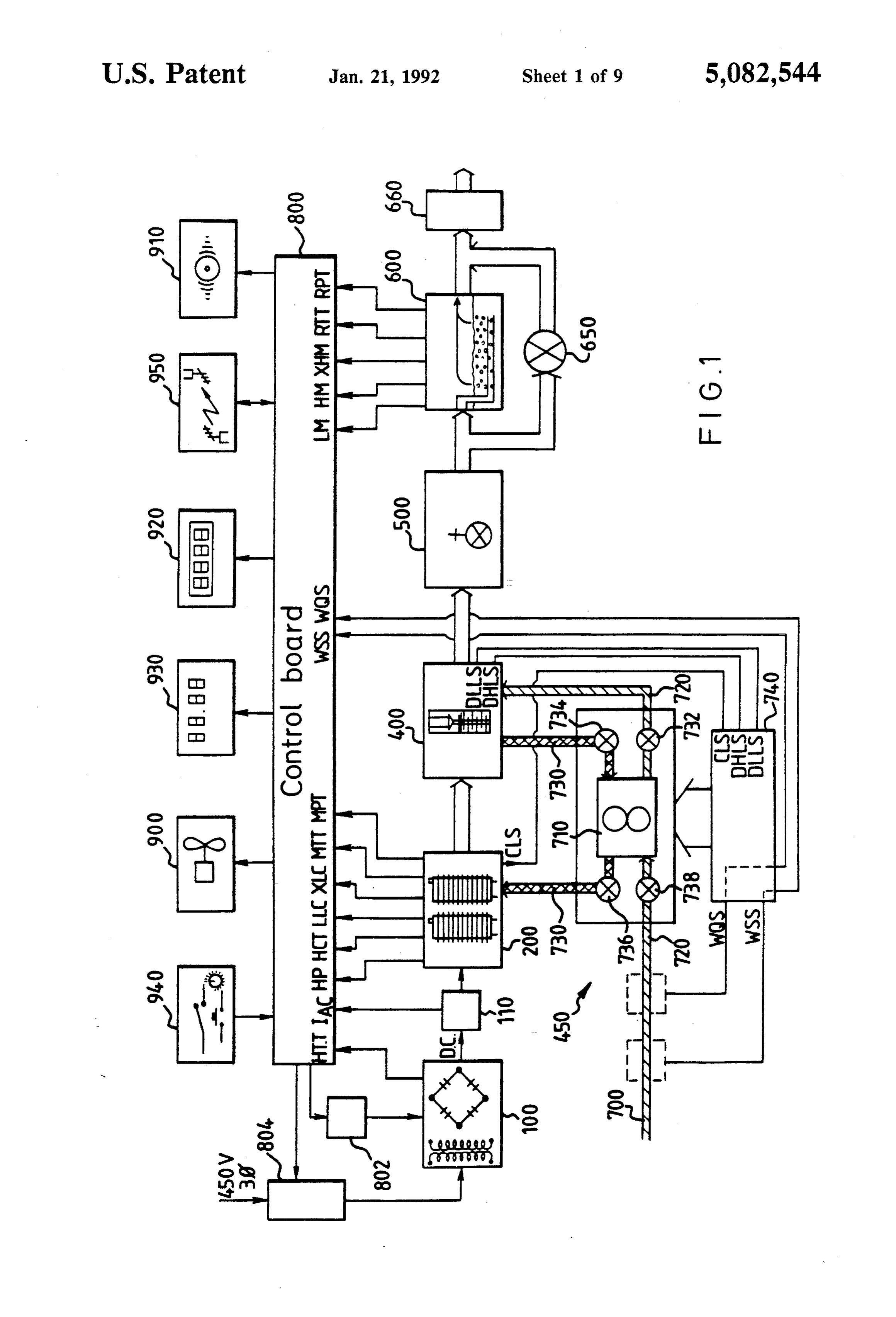
is provided an electrolytic cell comprising a container With reference to FIG. 1, a schematic diagram show for electrolyte, an electrode assembly disposed in the ing the main elements of the gas generating apparatus is container, the electrode assembly comprising a plurality shown. The principal operational elements comprise a of electrodes disposed in the container and an electrical 5 current transformers/rectifiers controllable d.c. power supply 100 which in connector outside the container; and a support member cludes for converting a three for supporting the electrodes and the support member supply suitable for electrolysingtowater phase alternating power supply a controllable d.c.
(preferably in abutting directly against the container, forming a seal the range 15-120 V D.C.). The d.c. output from the therewith.
power supply 100 is fed via a shunt 110, which is used as
Preferably the support member comprises an end-cap 20 a current measuring sensor, to a plurality of electrolytic for locating the electrodes relative to one another and is cells 200. Gas output from the cells 200 is fed to a demis of the form as recited in the first aspect of the invention. ter 400 which scrubs the gas, a gas flow regulator 500, According to the invention in an eight aspect of the a modifier invention there is provided an electrolytic cell compris teristics of 600, which modifies the combustion charac ing first sensing means for sensing a first condition of 25 trolled by a by-pass the the gas, degree of use of which is con valve 650, and a flash arrester 660.
the cell and first control means for reducing directly the The resulting gas mixture is fed from the flash arrestor cause of said condition, second sensing means for sens to a gas welding torch (not shown). ing at least one second condition of the cell and second The electrolytic cells 200 and demister 400 both use control means responsive to the second sensing means 30 deionized water as a working liquid, the electrolyte for for cutting power to the cell and third sensing means for the cells being potassium hydroxide (KOH). The elec sensing a third condition of the cell and third control trolytic cells 200 and dehumidifyer 400 are fed, on de means for cutting the power to the cell after a predeter mand, with deionized water by pumping system 450. mined delay and wherein the first, second and third Gas generation, temperature control, external display control means are independent of each other. 35 and fail safe alarm systems are controlled by main con Preferably, the first control means comprises a me trol board 800, which, for the control of gas generation, chanically operated pressure release valve, the second receives temperature and pressure measurements from control means trips a power supply relay and third the electrolytic cells 200 via main temperature and pres control means deactuates a power supply control cir sure sensors MTT and MPT, and from the modifier 600 Cult. via pressure and temperature sensors RTT and RPT
BRIEF DESCRIPTION OF THE DRAWINGS
and actual cell current, IAC, as measured by shunt 110.
Using this information and in accordance with the
An embodiment of the invention will now be de operational method shown in the flowchart of FIG. 12, scribed, by way of example, with reference to the ac the cell current is controlled by the control board 800, companying drawings in which: 45 by regulating the current controllable DC power sup FIG. 1 is a schematic diagram of the gas generating ply 100 by means for controller 802, which is preferably apparatus of the invention. a firing board for thyristor based switches within the FIG. 2 is a plan view of the electrolytic cell unit of power supply 100.
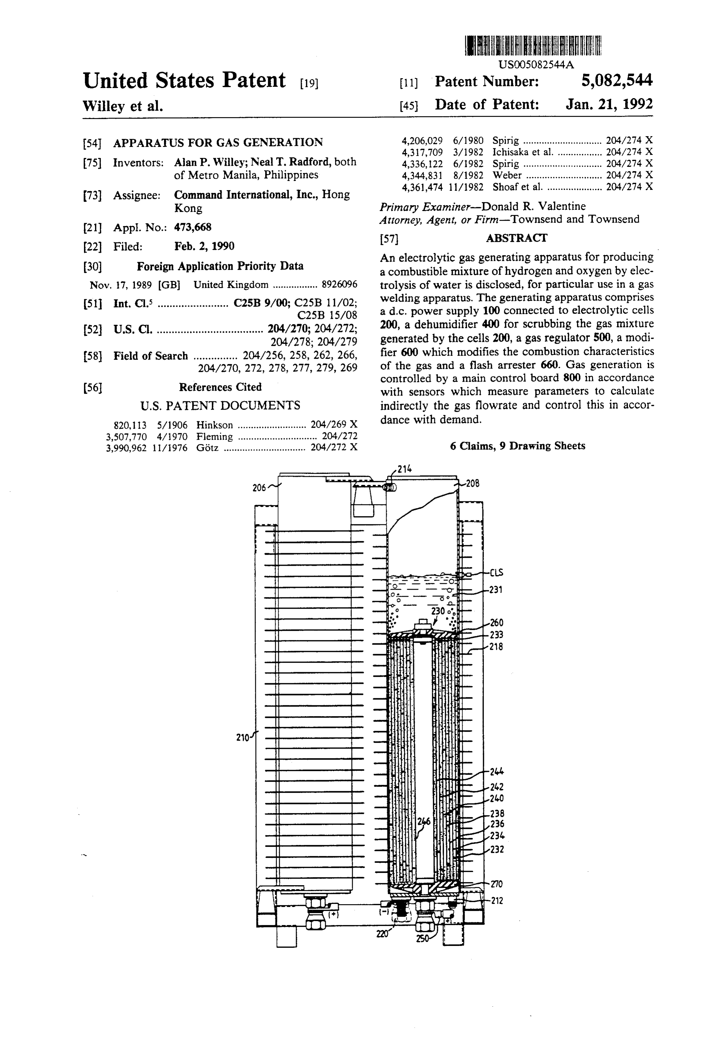
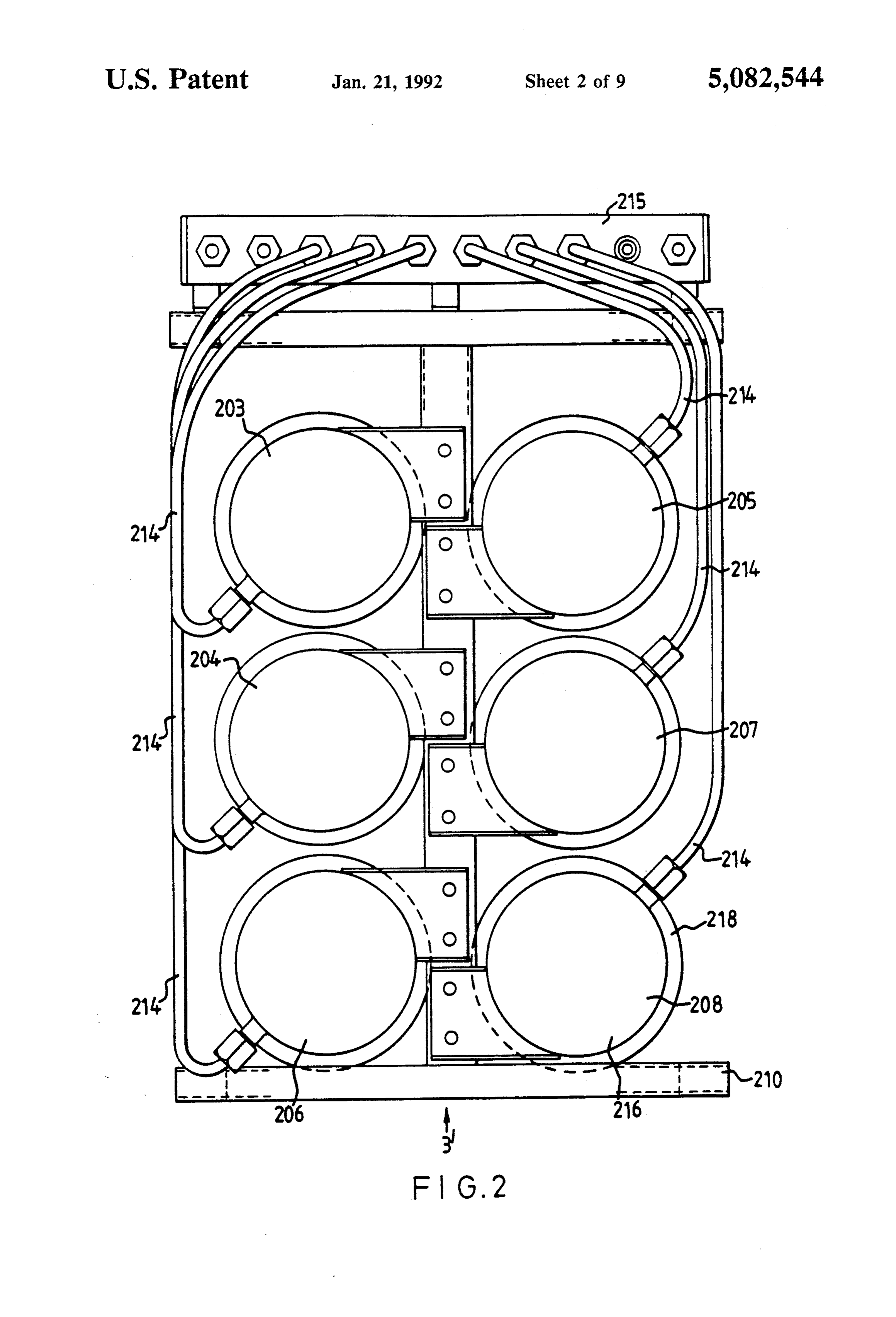
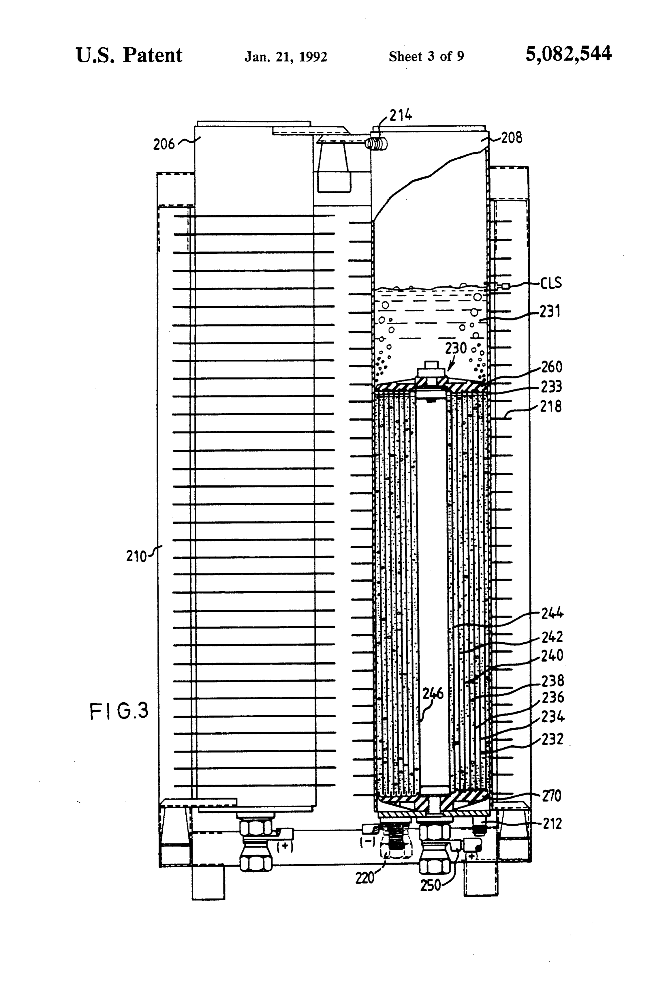
the appartus of FIG. 1. In addition to controlling the flow of gas mixture, the FIG. 3 is a side view of the unit of FIG. 2 in the 50 control board 800 also acts to control the working liq direction of arrow 3", partly sectioned. uid temperature of the electrolytic cells 200, by moni FIG. 4 is a plan view of a top end cap of the cell sensor this toring
MTT temperature through the main temperature and actuating fans 900 if the temperature shown in FIG. 3.
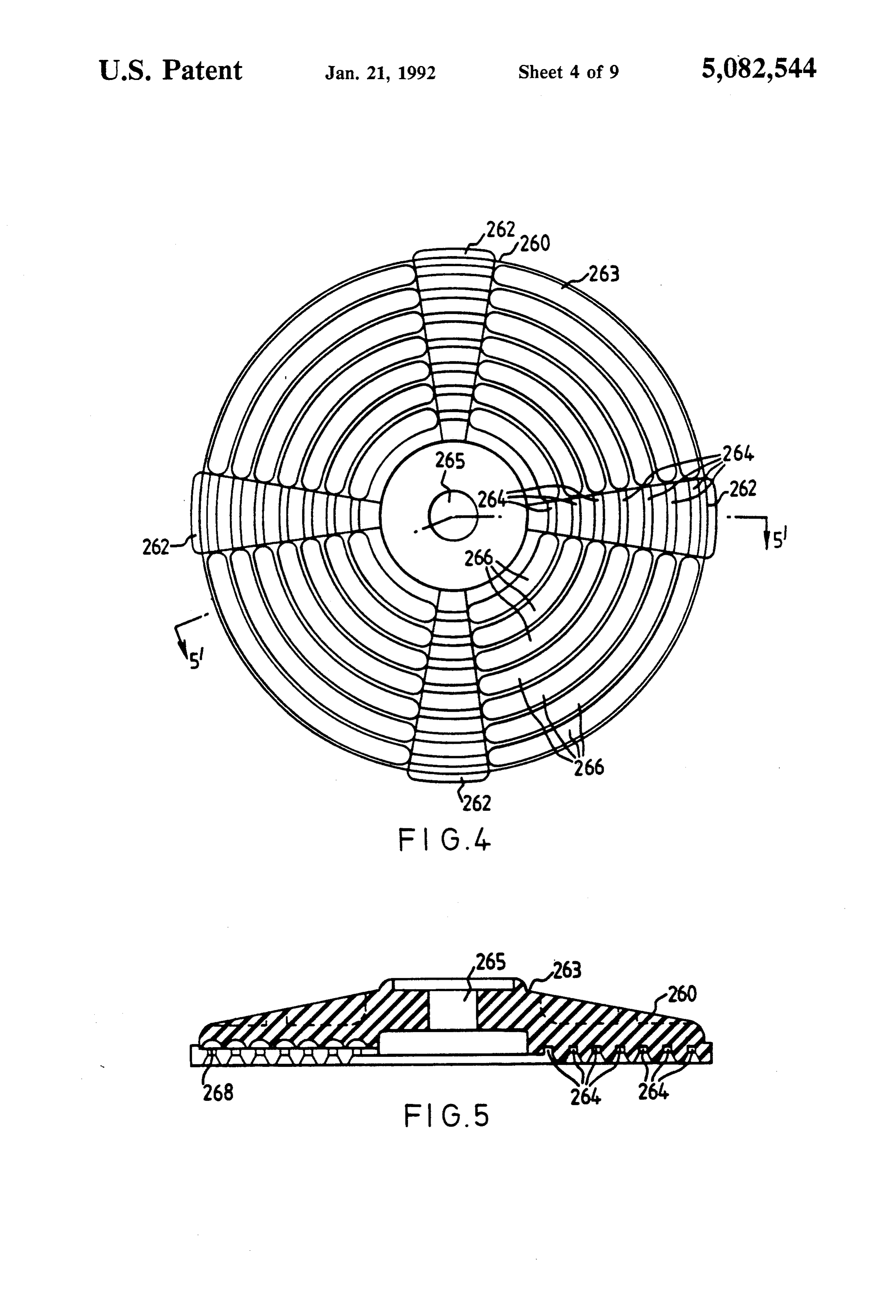
FIG. 5 is a view across section 5'-5" of FIG. 4. exceeds a preset limit, in the range 55-75 C., prefera bly 65° C. This control is needed to prevent over
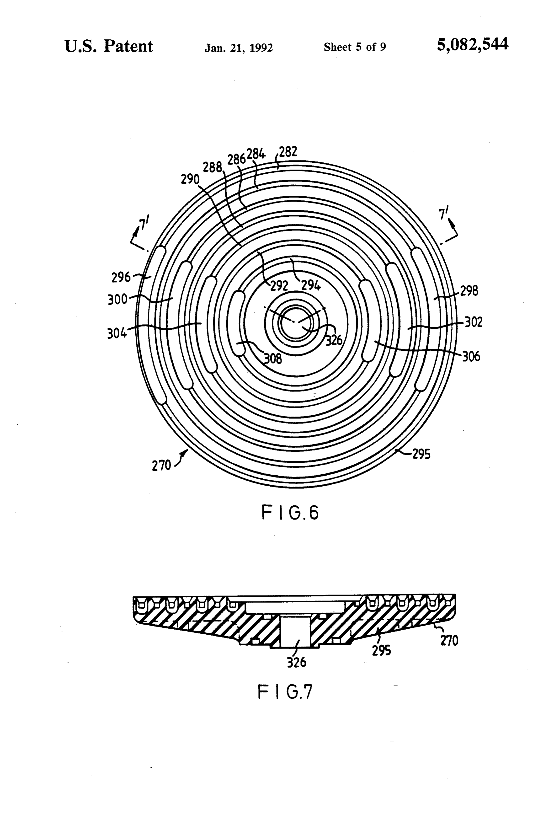
FIG. 6 is a plan view of a bottom end cap of the cell 55 entrainment shown in FIG, 3. of KOH via the gas flow and is chosen so that the KOH entrainment level is matched to the
FIG. 7 is a view across section 7'-7' of FIG. 6.
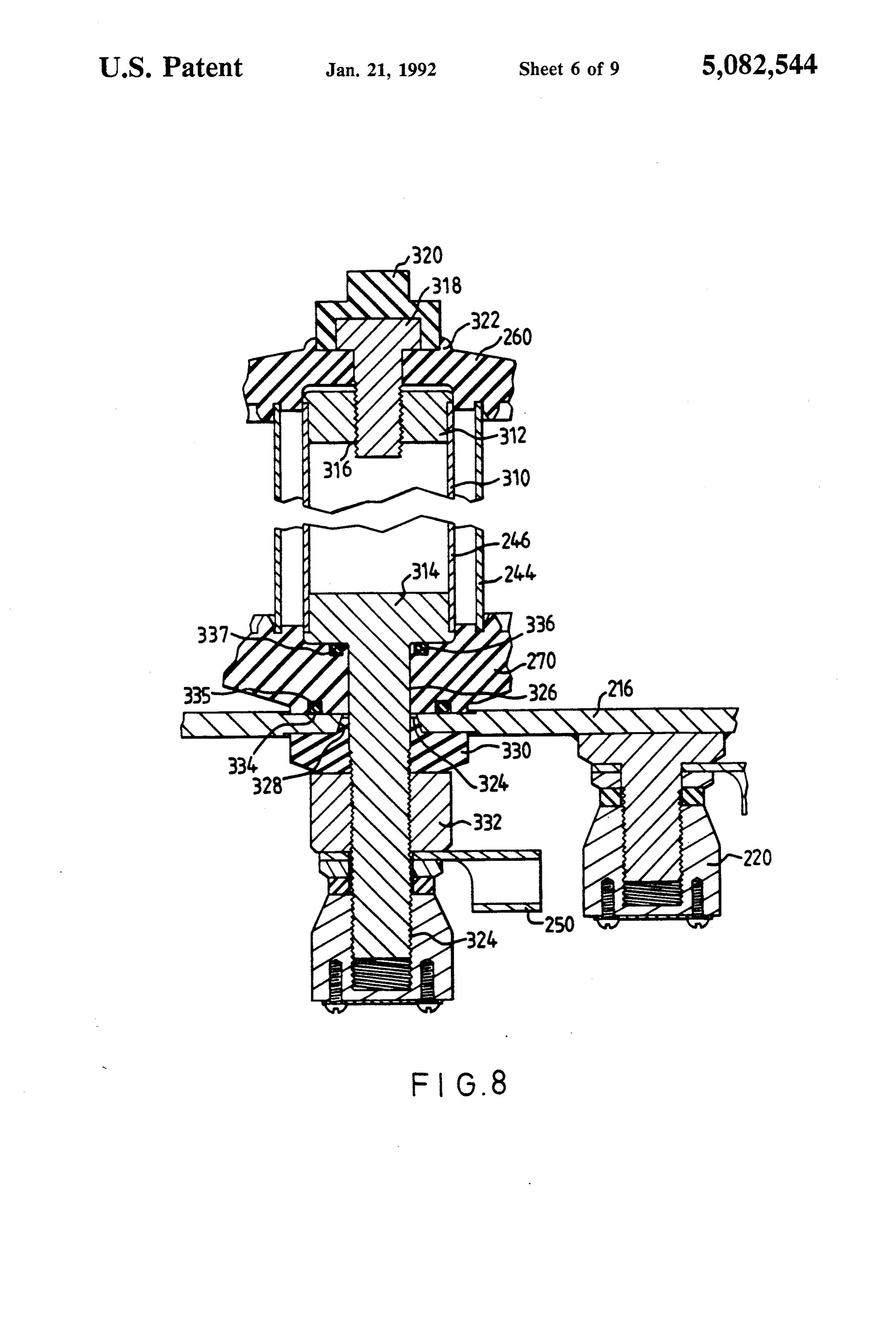
FIG. 8 is a sectional view of the mounting arrange demister's
For the vapour removal capacity.
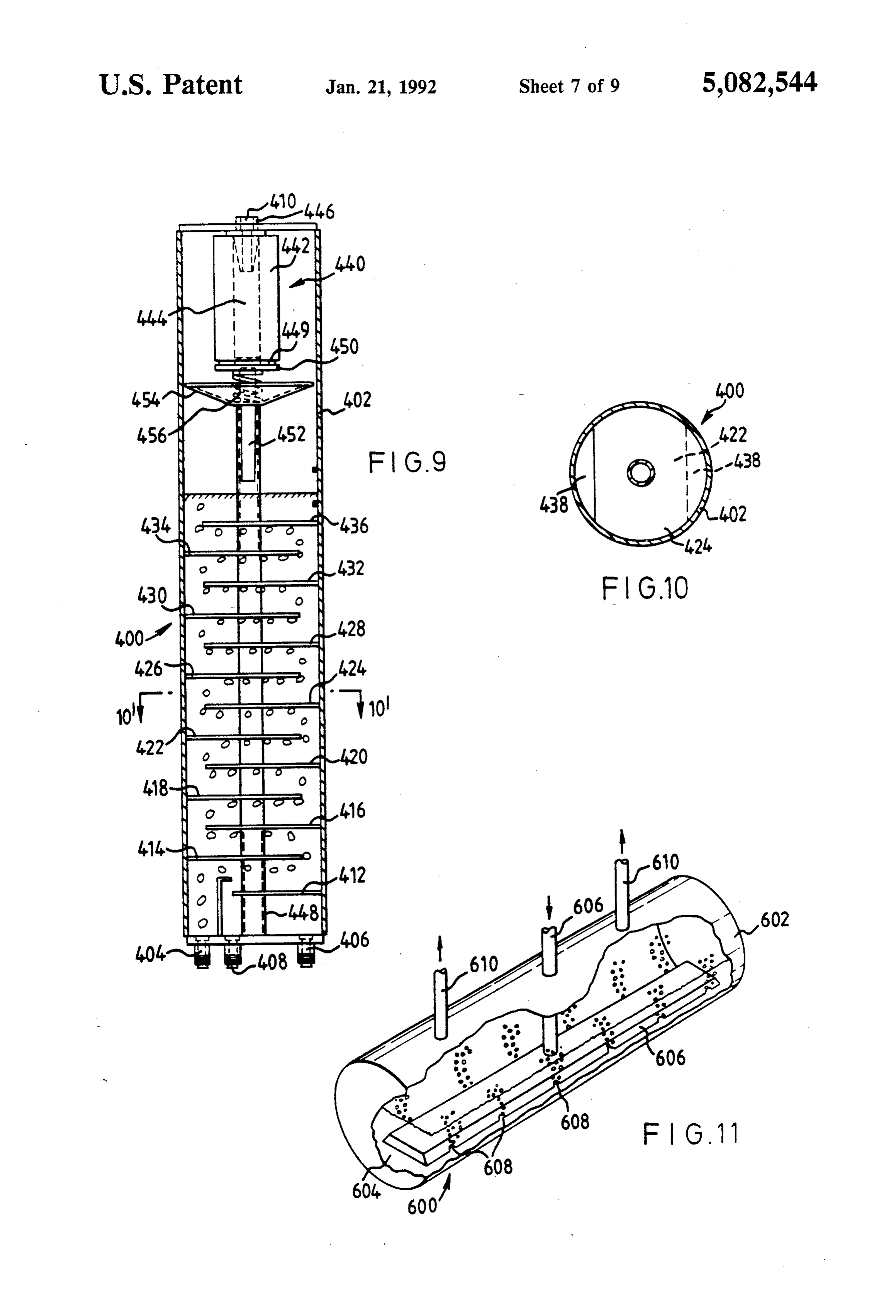
fail safe systems, the control board 800 moni pment of the cell of FIG. 3. 60 tors signals from other sensors, namely a hightrans FIG. 9 is a sectional view of the demister of FIG. 1. former temperature sensor HTT connected to the trans FIG. 10 is a view across section 10'-10' of FIG. 9. former of power supply 100, an extra low cell level FIG. 11 is a perspective part-sectional view of the water XLC, a high cell temperature sensor HCT and a nodifier of FIG. 1. high pressure sensor HP, all connected to the cells 200 FIG. 12 is a flow diagram illustrating the gas flow 65 and a modifier low liquid level sensor LM, a high modi control functions of the control board of FIG. 1. fier level sensor HM and an extra high modifier Level FIG. 13 is a schematic diagram of the fail-safe mecha sensor XHM all connected to modifer 400. The control nisms of the apparatus of FIG. 1. board 800 and pumping system 450 also receives further
Page 13
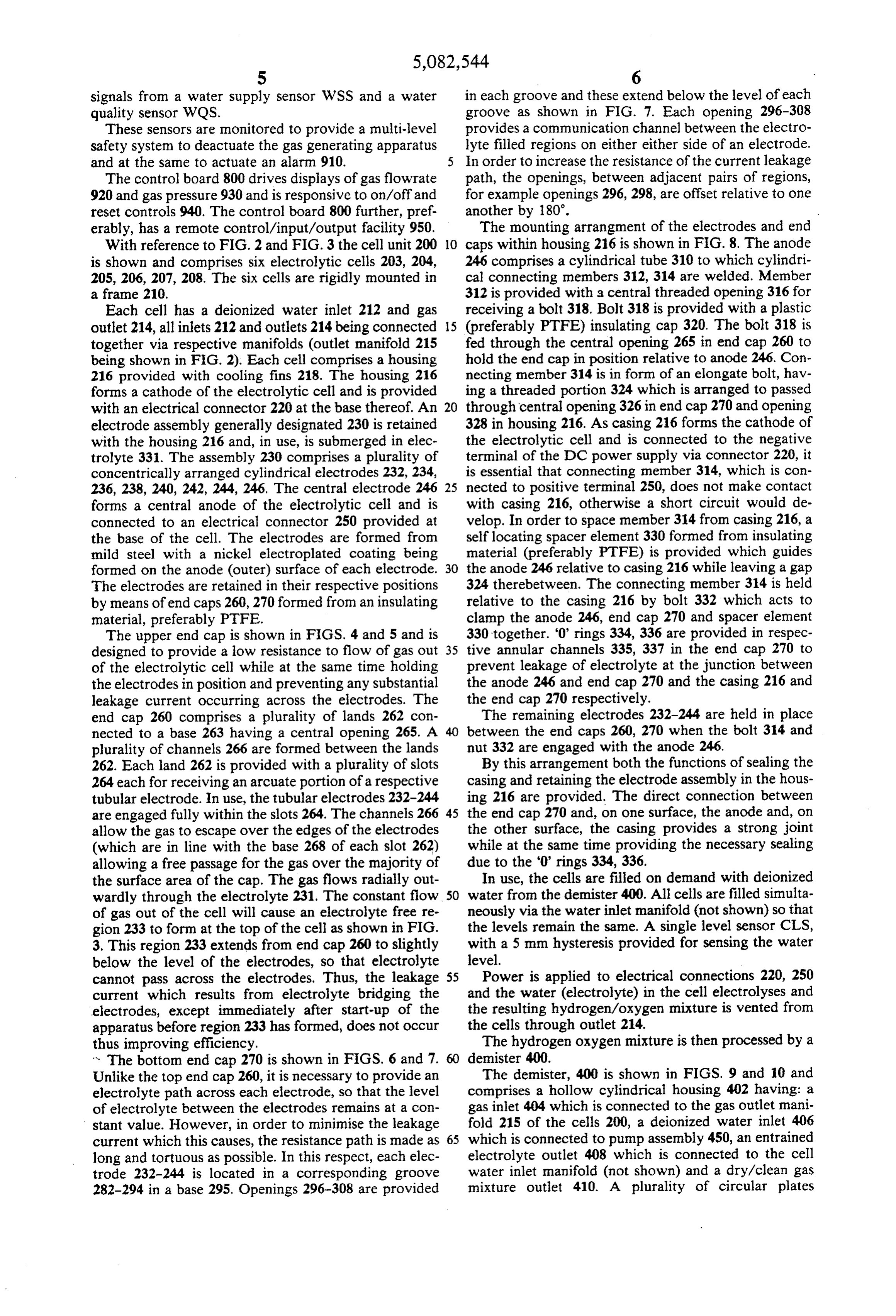
signals from a water supply sensor WSS and a water in each groove and these extend below the level of each quality sensor WQS. groove as shown in FIG. 7. Each opening 296–308 These sensors are monitored to provide a multi-level provides a communication channel between the electro safety system to deactuate the gas generating apparatus lyte filled regions on either either side of an electrode. and at the same to actuate an alarm 910. 5 In order to increase the resistance of the current leakage The control board 800 drives displays of gas flowrate path, the openings, between adjacent pairs of regions, 920 and gas pressure 930 and is responsive to on/off and for example openings 296,298, are offset relative to one reset controls 940. The control board 800 further, pref. another by 180°.
erably, has a remote control/input/output facility 950. The mounting arrangment of the electrodes and end With reference to FIG. 2 and FIG. 3 the cell unit 200 10 caps within housing 216 is shown in FIG.8. The anode is shown and comprises six electrolytic cells 203, 204, 246 comprises a cylindrical tube 310 to which cylindri 205, 206, 207, 208. The six cells are rigidly mounted in cal connecting members 312, 314 are welded. Member a frame 210. 312 is provided with a central threaded opening 316 for Each cell has a deionized water inlet 212 and gas receiving a bolt 318. Bolt 318 is provided with a plastic outlet 214, all inlets 212 and outlets 214 being connected 15 (preferably PTFE) insulating cap 320. The bolt 318 is together via respective manifolds (outlet manifold 215 fed through the central opening 265 in end cap 260 to being shown in FIG. 2). Each cell comprises a housing hold the end cap in position relative to anode 246. Con 216 provided with cooling fins 218. The housing 216 necting member 314 is in form of an elongate bolt, hav forms a cathode of the electrolytic cell and is provided ing a threaded portion 324 which is arranged to passed with an electrical connector 220 at the base thereof. An 20 through central opening 326 in end cap 270 and opening electrode assembly generally designated 230 is retained 328 in housing 216. As casing 216 forms the cathode of with the housing 216 and, in use, is submerged in elec the electrolytic cell and is connected to the negative trolyte 331. The assembly 230 comprises a plurality of terminal of the DC power supply via connector 220, it concentrically arranged cylindrical electrodes 232, 234, is essential that connecting member 314, which is con 236, 238, 240, 242, 244, 246. The central electrode 246 25 nected to positive terminal 250, does not make contact forms a central anode of the electrolytic cell and is with casing 216, otherwise a short circuit would de connected to an electrical connector 250 provided at velop. In order to space member 314 from casing 216, a the base of the cell. The electrodes are formed from self locating spacer element 330 formed from insulating mild steel with a nickel electroplated coating being material (preferably PTFE) is provided which guides formed on the anode (outer) surface of each electrode. 30 the anode 246 relative to casing 216 while leaving a gap The electrodes are retained in their respective positions 324 therebetween. The connecting member 314 is held by means of end caps 260,270 formed from an insulating relative to the casing 216 by bolt 332 which acts to material, preferably PTFE. clamp the anode 246, end cap 270 and spacer element The upper end cap is shown in FIGS. 4 and 5 and is 330 together. "0" rings 334, 336 are provided in respec designed to provide a low resistance to flow of gas out 35 tive annular channels 335, 337 in the end cap 270 to of the electrolytic cell while at the same time holding prevent leakage of electrolyte at the junction between the electrodes in position and preventing any substantial the anode 246 and end cap 270 and the casing 216 and leakage current occurring across the electrodes. The the end cap 270 respectively.
end cap 260 comprises a plurality of lands 262 con The remaining electrodes 232-244 are held in place nected to a base 263 having a central opening 265. A between the end caps 260, 270 when the bolt 314 and plurality of channels 266 are formed between the lands nut 332 are engaged with the anode 246. 262. Each land 262 is provided with a plurality of slots By this arrangement both the functions of sealing the 264 each for receiving an arcuate portion of a respective casing and retaining the electrode assembly in the hous tubular electrode. In use, the tubular electrodes 232-244 ing 216 are provided. The direct connection between are engaged fully within the slots 264. The channels 266 45 the end cap 270 and, on one surface, the anode and, on allow the gas to escape over the edges of the electrodes the other surface, the casing provides a strong joint (which are in line with the base 268 of each slot 262) while at the same time providing the necessary sealing allowing a free passage for the gas over the majority of due to the '0' rings 334,336.
the surface area of the cap. The gas flows radially out In use, the cells are filled on demand with deionized wardly through the electrolyte 231. The constant flow 50 water from the demister 400. All cells are filled simulta of gas out of the cell will cause an electrolyte free re neously via the water inlet manifold (not shown) so that gion 233 to form at the top of the cell as shown in FIG. the levels remain the same. A single level sensor CLS, 3. This region 233 extends from end cap 260 to slightly with a 5 mm hysteresis provided for sensing the water below the level of the electrodes, so that electrolyte level.
cannot pass across the electrodes. Thus, the leakage 55 Power is applied to electrical connections 220, 250 current which results from electrolyte bridging the and the water (electrolyte) in the cell electrolyses and electrodes, except immediately after start-up of the the resulting hydrogen/oxygen mixture is vented from apparatus before region 233 has formed, does not occur the cells through outlet 214.
thus improving efficiency. The hydrogen oxygen mixture is then processed by a * The bottom end cap 270 is shown in FIGS. 6 and 7. demister 400.
Unlike the top end cap 260, it is necessary to provide an The demister, 400 is shown in FIGS. 9 and 10 and electrolyte path across each electrode, so that the level comprises a hollow cylindrical housing 402 having: a of electrolyte between the electrodes remains at a con gas inlet 404 which is connected to the gas outlet mani stant value. However, in order to minimise the leakage fold 215 of the cells 200, a deionized water inlet 406 current which this causes, the resistance path is made as 65 which is connected to pump assembly 450, an entrained long and tortuous as possible. In this respect, each elec electrolyte outlet 408 which is connected to the cell trode 232-244 is located in a corresponding groove water inlet manifold (not shown) and a dry/clean gas 282-294 in a base 295. Openings 296–308 are provided mixture outlet 410. A plurality of circular plates
Page 14
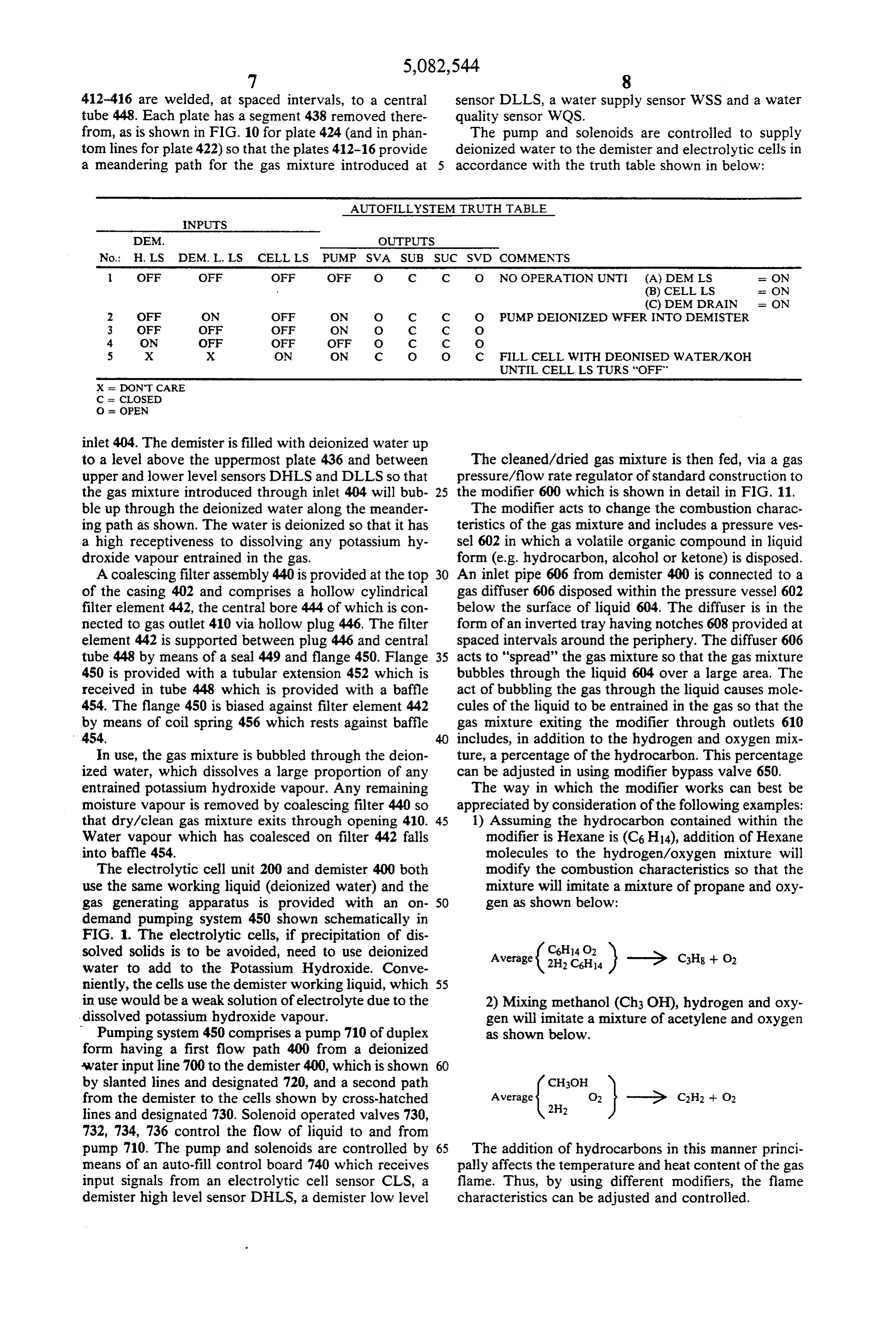
412-416 are welded, at spaced intervals, to a central sensor DLLS, a water supply sensor WSS and a water tube 448. Each plate has a segment 438 removed there quality sensor WQS.
from, as is shown in FIG. 10 for plate 424 (and in phan The pump and solenoids are controlled to supply tom lines for plate 422) so that the plates 412-16 provide deionized water to the demister and electrolytic cells in a meandering path for the gas mixture introduced at 5 accordance with the truth table shown in below:
AUTOFILLYSTEM TRUTH TABLE
NPUS
No.: H. LS DEM. L. LS CELL LS PUMP SVA SUB SUC SVD COMMENTS
OFF OFF OFF OFF O C C O NO OPERATION UNTI (A) DEM LS a ON (B) CELL LS is ON
(C) DEMDRAIN = ON
2 OFF ON OFF ON O C C O PUMP DEONIZED WFER INTO DEMISTER 3 OFF OFF OFF ON O C C O 4 ON OFF OFF OFF O C C O 5 X X ON ON C O O C FILL CELL WITH IDEONISED WATERAKOH
UNTIL CELL LSTURS 'OFF'
X - ON CARE
C = COSED
O = OPEN
inlet 404. The demister is filled with deionized water up to a level above the uppermost plate 436 and between The cleaned/dried gas mixture is then fed, via a gas upper and lower level sensors DHLS and DLLS so that pressure/flow rate regulator of standard construction to the gas mixture introduced through inlet 404 will bub 25 the modifier 600 which is shown in detail in FIG. 11. ble up through the deionized water along the meander The modifier acts to change the combustion charac ing path as shown. The water is deionized so that it has teristics of the gas mixture and includes a pressure ves a high receptiveness to dissolving any potassium hy sel 602 in which a volatile organic compound in liquid droxide vapour entrained in the gas. form (e.g. hydrocarbon, alcohol or ketone) is disposed. A coalescing filter assembly 440 is provided at the top 30 An inlet pipe 606 from demister 400 is connected to a of the casing 402 and comprises a hollow cylindrical gas diffuser 606 disposed within the pressure vessel 602 filter element 442, the central bore 444 of which is con below the surface of liquid 604. The diffuser is in the nected to gas outlet 410 via hollow plug 446. The filter form of an inverted tray having notches 608 provided at element 442 is supported between plug 446 and central spaced intervals around the periphery. The diffuser 606 tube 448 by means of a seal 449 and flange 450. Flange 35 acts to "spread' the gas mixture so that the gas mixture 450 is provided with a tubular extension 452 which is bubbles through the liquid 604 over a large area. The received in tube 448 which is provided with a baffle act of bubbling the gas through the liquid causes mole 454. The flange 450 is biased against filter element 442 cules of the liquid to be entrained in the gas so that the by means of coil spring 456 which rests against baffle gas mixture exiting the modifier through outlets 610 454. includes, in addition to the hydrogen and oxygen mix in use, the gas mixture is bubbled through the deion ture, a percentage of the hydrocarbon. This percentage ized water, which dissolves a large proportion of any can be adjusted in using modifier bypass valve 650. entrained potassium hydroxide vapour. Any remaining The way in which the modifier works can best be moisture vapour is renoved by coalescing filter 440 so appreciated by consideration of the following examples: that dry/clean gas mixture exits through opening 410. 45 1) Assuming the hydrocarbon contained within the Water vapour which has coalesced on filter 442 falls modifier is Hexane is (C6H14), addition of Hexane into baffle 454. molecules to the hydrogen/oxygen mixture will The electrolytic cell unit 200 and demister 400 both modify the combustion characteristics so that the use the same working liquid (deionized water) and the mixture will imitate a mixture of propane and oxy gas generating apparatus is provided with an on 50 gen as shown below: demand pumping system 450 shown schematically in
FIG. 1. The electrolytic cells, if precipitation of dis solved solids is to be avoided, need to use deionized Average water to add to the Potassium Hydroxide. Conve niently, the cells use the demister working liquid, which 55 in use would be a weak solution of electrolyte due to the 2) Mixing methanol (Ch3 OH), hydrogen and oxy dissolved potassium hydroxide vapour. gen will imitate a mixture of acetylene and oxygen Pumping system 450 comprises a pump 710 of duplex as shown below.
form having a first flow path 400 from a deionized -water input line 700 to the demister 400, which is shown by slanted lines and designated 720, and a second path from the demister to the cells shown by cross-hatched lines and designated 730. Solenoid operated valves 730,
Average ( 732, 734, 736 control the flow of liquid to and from pump 710. The pump and solenoids are controlled by 65 The addition of hydrocarbons in this manner princi means of an auto-fill control board 740 which receives pally affects the temperature and heat content of the gas input signals from an electrolytic cell sensor CLS, a flame. Thus, by using different modifiers, the flame demister high level sensor DHLS, a demister low level characteristics can be adjusted and controlled.
Page 15
The modifier pressure vessel 602 provides the added theory or experimentally using a standard current probe function of a gas mixture reservoir. and flowmeter.
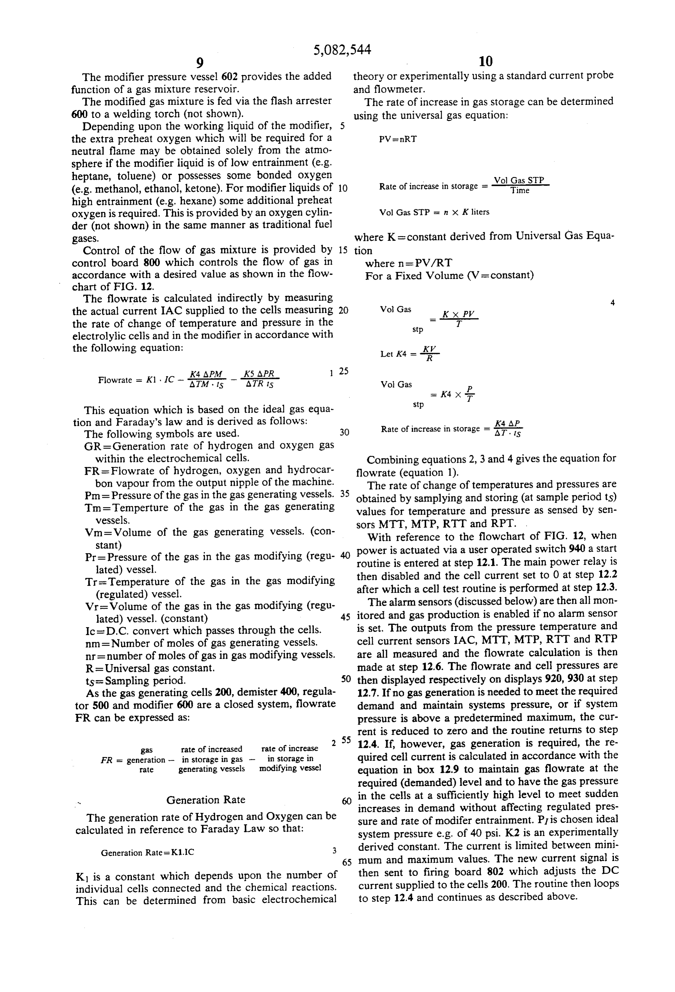
The modified gas mixture is fed via the flash arrester The rate of increase in gas storage can be determined 600 to a welding torch (not shown). using the universal gas equation: Depending upon the working liquid of the modifier, 5 the extra preheat oxygen which will be required for a PVenRT neutral flame may be obtained solely from the atmo sphere if the modifier liquid is of low entrainment (e.g.
heptane, toluene) or possesses some bonded oxygen Vol Gas STP (e.g. methanol, ethanol, ketone). For modifier liquids of O Rate of increase in storage = Time high entrainment (e.g. hexane) some additional preheat oxygen is required. This is provided by an oxygen cylin Vol Gas STP = n x Kliters der (not shown) in the same manner as traditional fuel gases. where K = constant derived from Universal Gas Equa Control of the flow of gas mixture is provided by 15 tion control board 800 which controls the flow of gas in where n = PV/RT accordance with a desired value as shown in the flow For a Fixed Volume (V= constant) chart of FIG. 12.
The flowrate is calculated indirectly by measuring 4 the actual current IAC supplied to the cells measuring 20 Vol. Gas = KXPK the rate of change of temperature and pressure in the stp T electrolylic cells and in the modifier in accordance with the following equation: Let K4 = - R -
K4. APM
ATRAPR
Vol Gas
This equation which is based on the ideal gas equa tion and Faraday's law and is derived as follows: K4 AP Rate of increase in storage = A.T. is
GR = Generation rate of hydrogen and oxygen gas within the electrochemical cells. Combining equations 2, 3 and 4 gives the equation for FR = Flowrate of hydrogen, oxygen and hydrocar flowrate (equation 1).
bon vapour from the output nipple of the machine. The rate of change of temperatures and pressures are Pm = Pressure of the gas in the gas generating vessels. 35 obtained by samplying and storing (at sample period ts) Tm=Temperture of the gas in the gas generating values for temperature and pressure as sensed by sen vessels.
Vm=Volume of the gas generating vessels. (con sorsWith MTT, MTP, RTT and RPT.
reference to the flowchart of FIG. 12, when stant)
Pr=Pressure of the gas in the gas modifying (regu routine isactuated power is entered via a user operated switch 940 a start at step 12.1. The main power relay is lated) vessel.
Tra-Temperature of the gas in the gas modifying then disabled and the cell current set to 0 at step 12.2 (regulated) vessel. after which a cell test routine is performed at step 12.3. Vr-Volume of the gas in the gas modifying (regu The alarm sensors (discussed below) are then all mon lated) vessel. (constant) 45 itored and gas production is enabled if no alarm sensor Ic = D.C. convert which passes through the cells. is set. The outputs from the pressure temperature and nm = Number of moles of gas generating vessels. cell current sensors IAC, MTT, MTP, RTT and RTP nr= number of moles of gas in gas modifying vessels. are all measured and the flowrate calculation is then R = Universal gas constant. made at step 12.6. The flowrate and cell pressures are ts= Sampling period. 50 then displayed respectively on displays 920, 930 at step As the gas generating cells 200, demister 400, regula 12.7. If no gas generation is needed to meet the required tor 500 and modifier 600 are a closed system, flowrate demand and maintain systems pressure, or if system FR can be expressed as: pressure is above a predetermined maximum, the cur rent is reduced to zero and the routine returns to step gas rate of increased rate of increase 55 12.4. If, however, gas generation is required, the re
FR = generation - in storage in gas - in storage in quired cell current is calculated in accordance with the Tate generating vessels modifying vessel equation in box 12.9 to maintain gas flowrate at the required (demanded) level and to have the gas pressure - Generation Rate in the cells at a sufficiently high level to meet sudden increases in demand without affecting regulated pres
The generation rate of Hydrogen and Oxygen can be sure and rate of modifer entrainment. PI is chosen ideal calculated in reference to Faraday Law so that: system pressure e.g. of 40 psi. K2 is an experimentally
derived constant. The current is limited between mini 65 mum and maximum values. The new current signal is
K1 is a constant which depends upon the number of then sent to firing board 802 which adjusts the DC individual cells connected and the chemical reactions. current supplied to the cells 200. The routine then loops This can be determined from basic electrochemical to step 12.4 and continues as described above.
Page 16
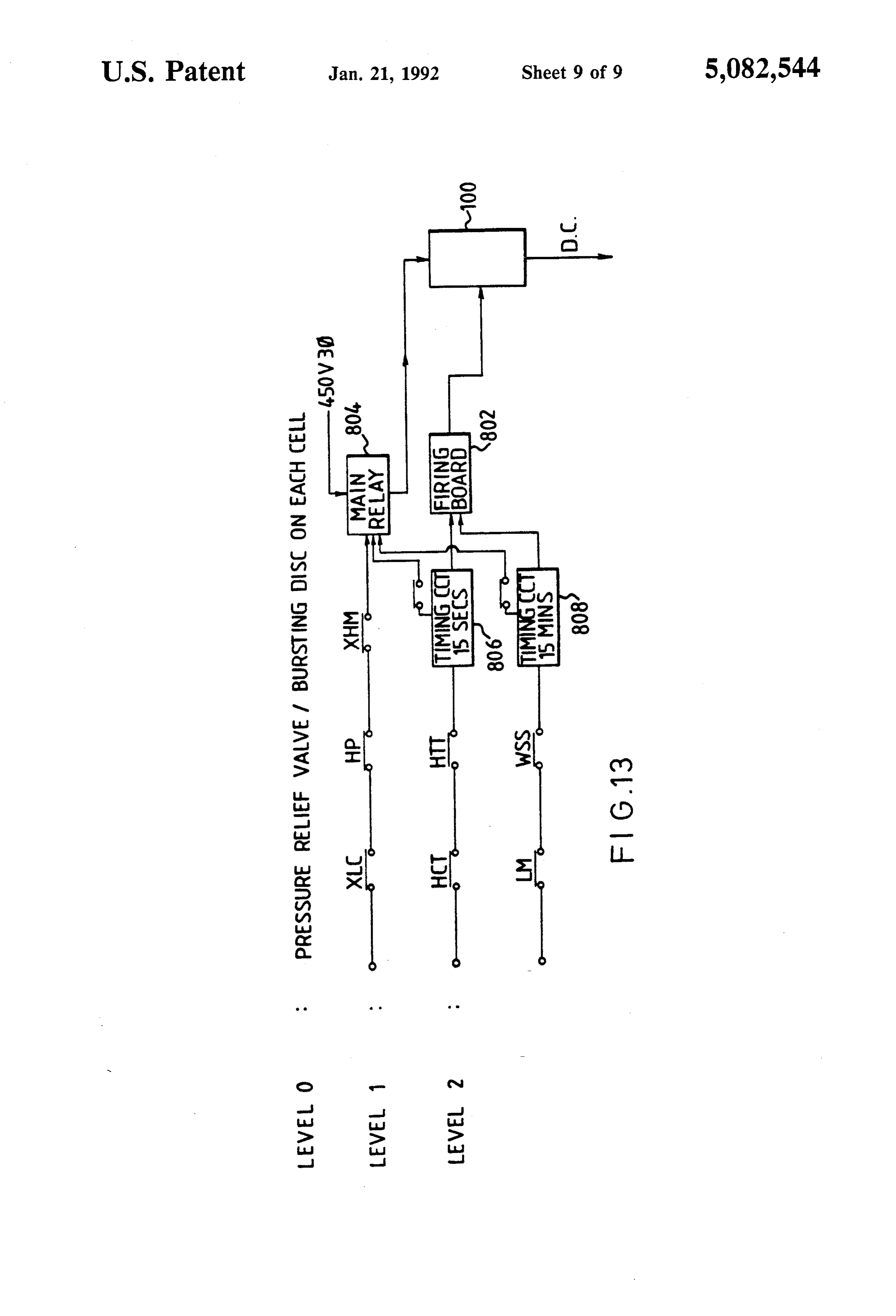
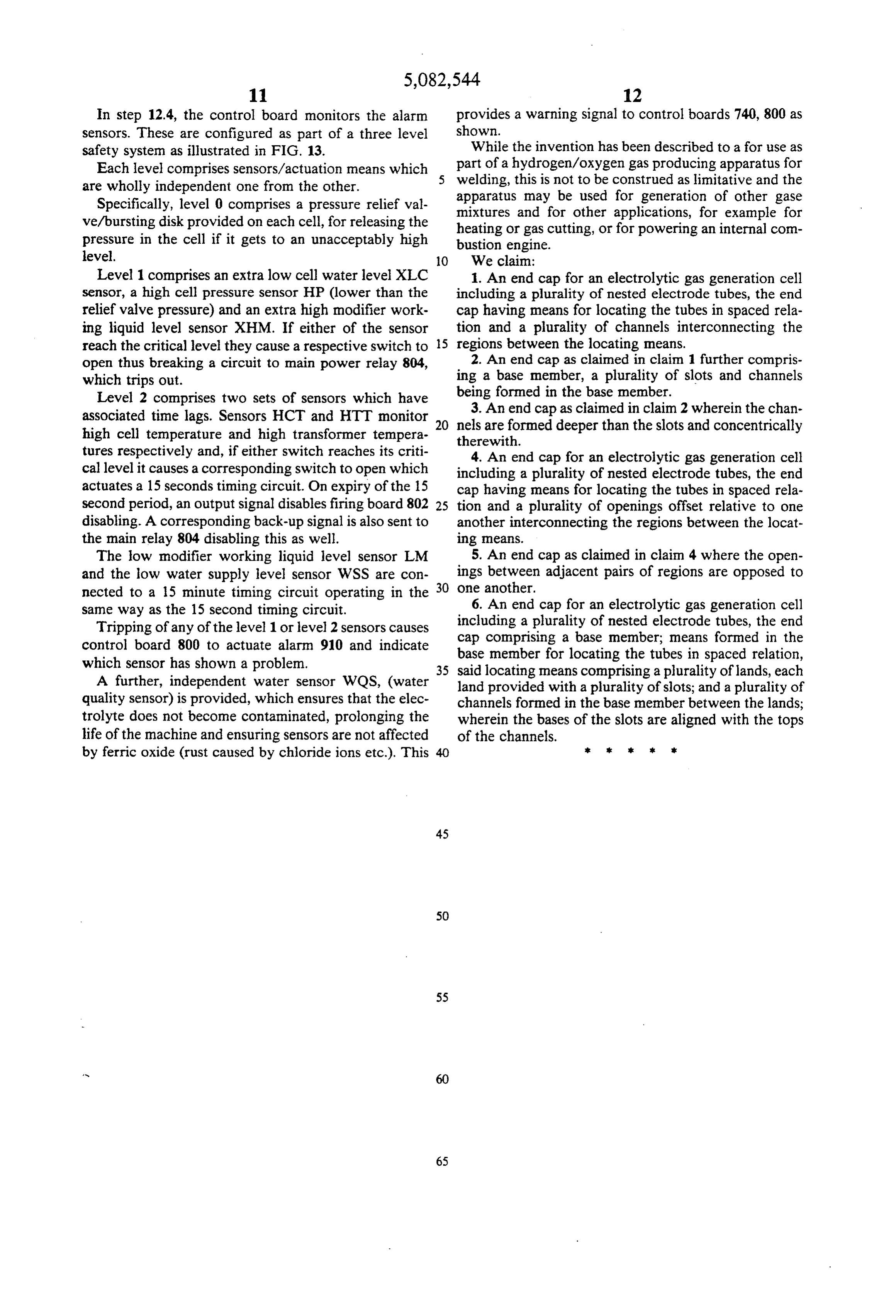
In step 12.4, the control board monitors the alarm provides a warning signal to control boards 740, 800 as sensors. These are configured as part of a three level shown.
safety system as illustrated in FIG. 13. While the invention has been described to a for use as Each level comprises sensors/actuation means which part of a hydrogen/oxygen gas producing apparatus for are wholly independent one from the other. welding, this is not to be construed as limitative and the Specifically, level 0 comprises a pressure relief val apparatus may be used for generation of other gase ve/bursting disk provided on each cell, for releasing the mixtures and for other applications, for example for pressure in the cell if it gets to an unacceptably high heating or gas cutting, or for powering an internal com level.
bustion engine.
O We claim:
Level 1 comprises an extra low cell water level XLC 1. An end cap for an electrolytic gas generation cell sensor, a high cell pressure sensor HP (lower than the including a plurality of nested electrode tubes, the end relief valve pressure) and an extra high modifier work cap having means for locating the tubes in spaced rela ing liquid level sensor XHM. If either of the sensor tion and a plurality of channels interconnecting the reach the critical level they cause a respective switch to 5 regions between the locating means. open thus breaking a circuit to main power relay 804, 2. An end cap as claimed in claim 1 further compris which trips out. ing a base member, a plurality of slots and channels Level 2 comprises two sets of sensors which have being formed in the base member.
associated time lags. Sensors HCT and HTT monitor 20 nels3. are An end cap as claimed in claim 2 wherein the chan formed deeper than the slots and concentrically high cell temperature and high transformer tempera therewith.
tures respectively and, if either switch reaches its criti 4. An end cap for an electrolytic gas generation cell cal level it causes a corresponding switch to open which including a plurality of nested electrode tubes, the end actuates a 15 seconds timing circuit. On expiry of the 15 cap having means for locating the tubes in spaced rela second period, an output signal disables firing board 802 25 tion and a plurality of openings offset relative to one disabling. A corresponding back-up signal is also sent to another interconnecting the regions between the locat the main relay 804 disabling this as well. ing means.
The low modifier working liquid level sensor LM 5. An end cap as claimed in claim 4 where the open and the low water supply level sensor WSS are con ings between adjacent pairs of regions are opposed to nected to a 15 minute timing circuit operating in the 30 one another.
same way as the 15 second timing circuit. 6. An end cap for an electrolytic gas generation cell including a plurality of nested electrode tubes, the end
Tripping of any of the level 1 or level 2 sensors causes cap comprising control board 800 to actuate alarm 910 and indicate a base member; means formed in the which sensor has shown a problem. base member for locating the tubes in spaced relation, 35 said locating means comprising a plurality of lands, each
A further, independent water sensor WQS, (water land provided with a plurality of slots; and a plurality of quality sensor) is provided, which ensures that the elec channels formed in the base member between the lands; trolyte does not become contaminated, prolonging the wherein the bases of the slots are aligned with the tops life of the machine and ensuring sensors are not affected of the channels.
by ferric oxide (rust caused by chloride ions etc.). This 40 ar s: k k s
Provenance
- Collection
- Cited prior art
- Original PDF
- patentimages.storage.googleapis.com →
- Filed
- 1990-02-02
- Pages
- 16
- Method
- pdftotext (the PDF's own text layer) + pdftoppm 300dpi page scans
- Source
- Google Patents bibliographic record
- Granted
- 1992-01-21
- Inventors
- Alan P. Willey; Neal T. Radford; Command International Inc
- Transcribed from
- patentimages.storage.googleapis.com →