patent · US20110220516A1
Hydrogen/oxygen generator with d.c. servo integrated control
15 September 2011
Page 1 — bibliographic record
(19) United States (12) Patent Application Publication (10) Pub. No.: US 2011/0220516 A1
Finfrock et al. (43) Pub. Date: Sep. 15, 2011 (54) HYDROGENAOXYGEN GENERATOR WITH Publication Classification
D.C. SERVO INTEGRATED CONTROL
(76) Inventors: Timm J. Finfrock, Shelby C25B I/04 (2006.01) Township, MI (US); James D. Hill, C25B 5/02 (2006.01) Lexington, KY (US); David A. C25B 9/00 (2006.01) Bateman, JR., Lexington, KY (US) (52) U.S. Cl. ...................................... 205/628; 204/228.6
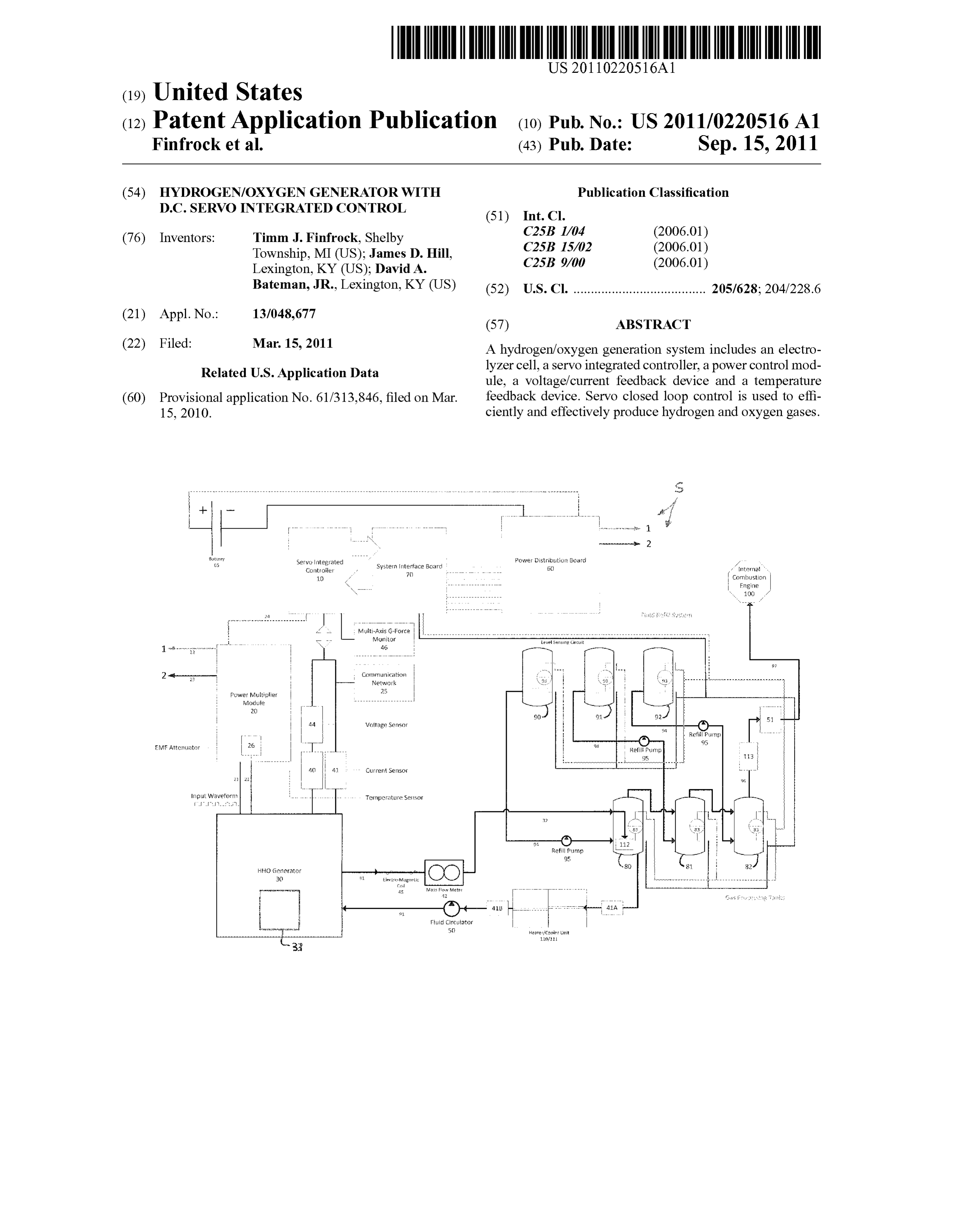
(22) Filed: Mar. 15, 2011 A hydrogen/oxygen generation system includes an electro Related U.S. Application Data lyZer cell, a servo integrated controller, a power control mod ule, a Voltage/current feedback device and a temperature (60) Provisional application No. 61/313,846, filed on Mar. feedback device. Servo closed loop control is used to effi 15, 2010. ciently and effectively produce hydrogen and oxygen gases.
8ster, Power listibutio? Board 35 segligated Systeinterface Board 50 x intens ''.
Combustion
Fngine
1 --------" " 38
s: Communication kis 9 : ... . . . . . . .. .
a. Network
Midtjie 3) ----- 9. 3. 2 : 51
Voltage Sensor
: () Refil Parmy
EM, Aiferator 26 : 9s Refil Pump : : 95 113
Crief Seilso ---
input waveform Temperature Sessor
i) Getrator
Lic Circuito
lifi
Page 2
Drawing sheet — no readable text.
Page 3
US 2011/022051.6 A1 Sep. 15, 2011
HYDROGENAOXYGEN GENERATOR WITH vomechanism or servo is a device used to provide control of D.C. SERVO INTEGRATED CONTROL a desired operation through the use of continuous feedback. The use of servo technology is not obvious in this application because most all servo applications deal with control of 0001. This application claims priority to U.S. Provisional motion; motor control for speed/direction, or linear applica Patent Application Ser. No. 61/313,846, filed 15 Mar. 2010, tion for control of cylinders or slides. The widely recognized the entire disclosure of which is incorporated herein by ref application is in robotic application where machine motions CCC. are controlled using three dimensional algorithms to move the robot hand to a precise location in a space (work frame). By
TECHNICAL FIELD AND INDUSTRIAL applying D.C. servo closed loop control to an electrolysis cell APPLICABILITY OF THE INVENTION a more precise control of the process is attained. 0002 This document relates generally to the generation of SUMMARY OF THE INVENTION hydrogen and oxygen gases from water.
0011. A hydrogen/oxygen generation system comprises
BACKGROUND OF THE INVENTION an electrolyzer cell including an electrolysis plate assembly, a servo integrated controller and a power control module con 0003 Water electrolysis simply put is the decomposition nected to the electrolysis plate assembly of the servo inte of water into hydrogen (H2) and oxygen (O) by passing an grated controller. The system further includes a Voltage/cur electrical current through it. rentfeedback device and a temperature feedback device, both 0004 Over the past decade plus, many improvements have of which are connected to the servo integrated controller. been made to the electrolyzer cell used for the electrolysis Advantageously, the system provides servo closed loop con process; from the glass jars that dangled the plate assemblies trol that more efficiently and effectively produces hydrogen in liquid to heavy plastic pipes and now more notably, thick and oxygen gases from water in the electrolyzer cell. polymer plates Sandwiching together stainless steel and seal 0012. In accordance with an additional aspect, a method is ing materials to form a solid mass or “Brick” type device but, provided for generating oxygen and hydrogen from water and very little has been done to improve the electric control of the electrolyte in an electrolyzer cell. The method comprises the process. steps of subjecting the water and electrolyte in the electro 0005. Inherent problems with direct current (D.C.) water lyzer cell to electricity in order to electrolyze the water and electrolysis are well known. One involves the need to use an generate oxygen and hydrogen gases, monitoring the elec electrolyte (catalyst) to improve electrical conduction. Spe trolysis process with a Voltage/current feedback device and a cifically, as the electrolyzed water begins to conduct and temperature feedback device both connected to a servo inte draws current this causes heat to be produced. As the heat grated controller and using servo closed loop continuous rises, so does the conduction. This thermal conduction cycle feedback to control operating parameters including (a) fre continues until thermal “runaway” occurs at which point the quency, current and Voltage of electricity and (b) temperature electrolysis cell looks like a dead short to the power supply— of the water and electrolyte.
drawing enormous currents until damaging the power Supply. 0013. In the following description there is shown and 0006 Another major problem is power consumption. described several different embodiments of the invention, Large amounts of power are required to Sustain D.C. water simply by way of illustration of some of the modes best suited electrolysis as seen above and because D.C. is constant, 100% to carry out the invention. As it will be realized, the invention of the power supplied is consumed by the device. is capable of other different embodiments and its several 0007 Recently, pulse-width modulators or PWM's as they details are capable of modification in various, obvious aspects are known have been used by some in an attempt to control the all without departing from the invention. Accordingly, the operating state of the elctrolyzer. Unfortunately, these drawings and descriptions will be regarded as illustrative in “dumb' devices cannot tell how well they work in the circuit nature and not as restrictive.
so a lot of "tweaking is necessary to keep these systems in tune'. BRIEF DESCRIPTION OF THE DRAWINGS 0008 PWM controller technology was commercially 0014. The accompanying drawings incorporated herein developed in the 1970's as a means of A.C. electric motor and forming a part of the specification, illustrate several control. Such electric motors are inductive devices where as an electrolytic cell is more a resistive circuit with capacitive aspects of the present invention and together with the descrip attributes. PWM's work by switching the supply current on tion serve to explain certain principles of the invention. In the and off very fast at varying rates like 120 HZina lamp dimmer drawings:
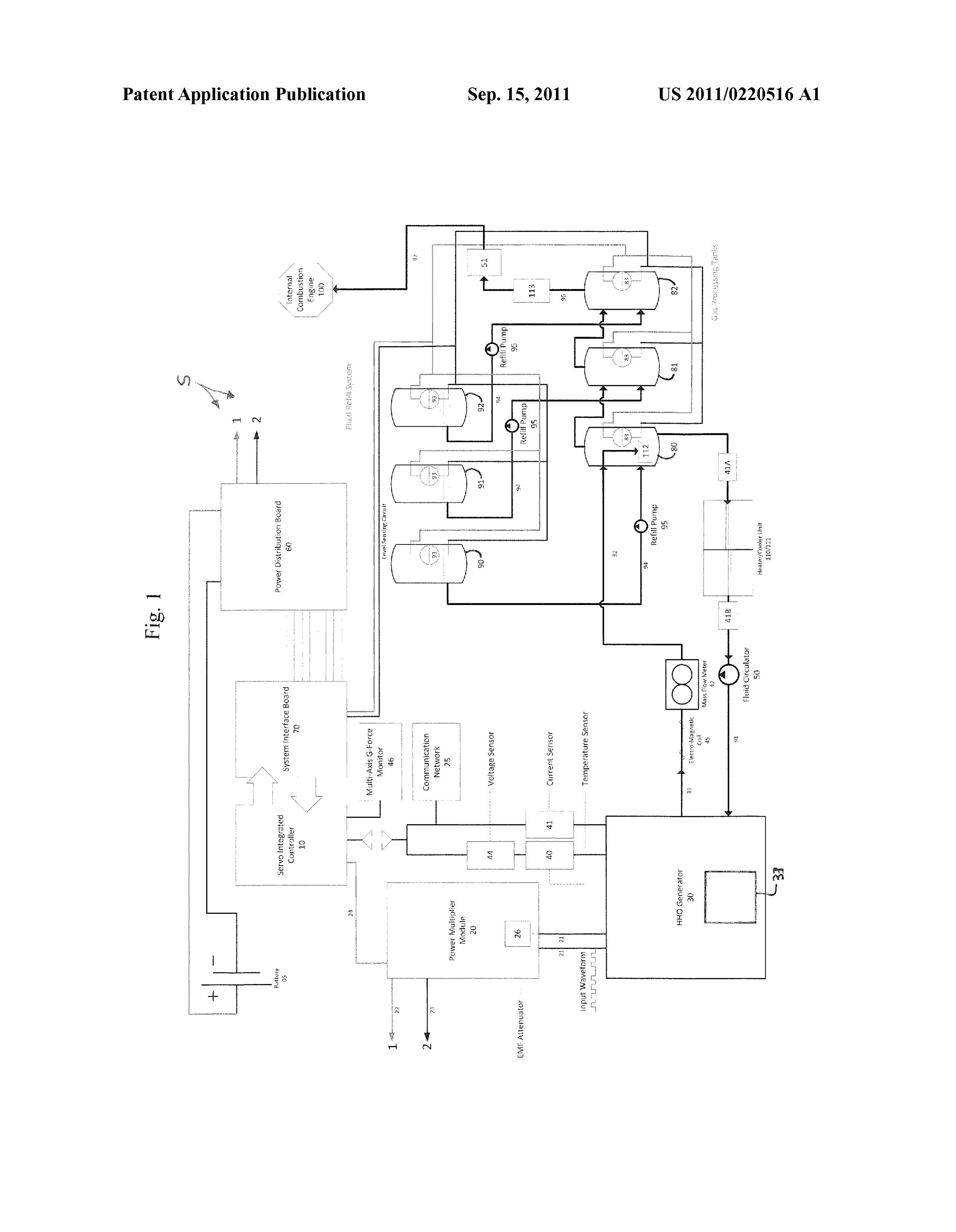
to 15-20 Khz in a computer power supply. By providing full 0015 FIG. 1 is a schematical block diagram of the hydro power for part of the time less power is consumed. gen/oxygen generation system described in detail below. 0009. Another method of mitigating the thermal (current) DETAILED DESCRIPTION OF THE PREFERRED runaway is to monitor the temperature. Once it exceeds the EMBODIMENTS OF THE INVENTION acceptable level, the device is switched off to let it cool down, like the thermostat in your house. The problem is that when 0016 Reference is now made to FIG. 1 schematically the device is switched off no gas is produced. Many other illustrating a hydrogen/oxygen generation system S. The gen means of “open loop” control have been attempted in the past eration system Sincludes an electrolyzer cell 30 including an but none have produced the desired control over the electro electrolysis plate assembly 33. The system S also includes a lytic cell. servo integrated controller 10 operatively connected to a 0010. This document describes a novel and effective power control module 20, a voltage/current feedback device approach that utilizes D.C. servo closed loop control. A ser in the form of a current sensor 40 and Voltage sensor 44 and a
Page 4
US 2011/022051.6 A1 Sep. 15, 2011
temperature feedback device in the form of temperature sen that might otherwise becaused by current spikes. More spe sors 41,41A and 41B. Advantageously, the controller 10 uses cifically, the electrolytic cell 30 is initially powered at a pre servo closed loop control to more efficiently and effectively determined period rate according to preset parameters of the produce hydrogen and oxygen gases from water in the elec SIC 10. Toward this end the output of the pulse width modu trolyzer cell 30. The electrolyzer cell 30 and the servo inte lator is varied starting at 1% to 99% depending on predeter grated controller 10 are more fully described below. mined and set operating parameters. 0017. The system S further includes a water and electro 0023 The method also includes steps of initializing and lyte supply vessel 80, a separator/aerator vessel 81 and a maintaining a desired level of: (1) distilled water and electro secondary aerator/flashback arrestor 82. A fluid circulator 50 lyte in the electrolyte supply vessel on tank 80; (2) separator/ pumps distilled water and electrolyte from the vessel 80 to the stripper in the separator/aerator vessel on tank 81 and (3) electrolyzer cell 30 through the conduit 91. A heater and conditioner-dryer in the secondary aerator/flashback arrestor cooler unit 110, 111 connected to the controller 10 allows the 82. In addition, the method includes circulating water and system S to maintain the water and electrolyte at a desired electrolyte from the water and electrolyte supply vessel 80 to operating temperature between, for example, -40 and 125 the electrolytic cell 30 at a predetermined rate set by the degrees C. Temperature sensors 41A and 41B provide the controller 10 once a desired operating temperature has been controller 10 with continuous temperature monitoring on reached.
each side of the heater and cooler unit 110, 111. The tempera 0024 Typically distilled water is used as the source of the ture sensory 41 monitors the temperature of the water and hydrogen and oxygen to be generated. Electrical conduction electrolyte inside the electrolyzer cell 30. is increased by adding an alkaline or acid based electrolyte 0018. A water and electrolyte reserve reservoir 90, a sepa (eg. Sodium hydroxide or nitric acid). If an alkaline electro rator/stripper reserve reservoir 91 and a conditioner-dryer lyte is used, the separator/aerator vessel or tank 81 includes reservoir 92 are connected, respectively, to the vessel 80. water and an acidic neutralizer Such as sodium bicarbonate. If vessel 81 and arrestor82. The reserve reservoirs 90,91 and 92 an acid electrolyte is used, the separator/aerator vessel or tank are used to refill and maintain proper fluid levels in the respec 81 includes water and an alkaline neutralizer Such as acetal tive vessels 80, 81 and arrestor 82 as described in greater acid. Water and/or a chemical conditioner agent Such as detail below. hydroxyls are provided in the arrestor or vessel 82. 0019. An exhaust conduit 90 connects the exhaust port of Example 1 the electrolyzer cell 30 to a gas serrator 112. The serrator 112 functions to strip electrolyte and fluid from the generated 0025. The following description of one possible embodi hydrogen and oxygen gas. Thus, the fluid in vessel 80 is ment of a hydrogen/oxygen generation system is a fundamen prevented from passing into vessel 81 while the hydrogen and tal example in nature and is in no way intended to limit the oxygen gasses (HHO gases) are allowed to pass freely into the system in its applications and/or uses. fluid in tank 81 for further stripping. As the HHO gas aerates 0026. The hydrogen/oxygen generation system Sincludes out of the fluid in vessel 81 it passes into the fluid in the a servo integrated controller 10 that provides a method of arrestor 82. The HHO gas then aerates out of that fluid and control of one or more electrolyzer cells 30. Each electrolyzer passes via conduit 96 to the gas micronizer 113 where the gas cell 30 may assume any configuration that employs an anodic is coalesced down to a size that can pass through the pressure plate(s), a cathodic plates(s), and or a with a series neutral infuser 51. The pressure infuser 51 controls the amount and plates (note electrolysis plate assembly 33) whereby a fluid is pressure of HHO gas passed via conduit 97 for infusion into used as an electrolyte to conduct current for the basic prin the intake airstream of the engine 100. The controller 10 sets ciple of electrolysis of a fluid into constituent gases under the amount and pressure (rate) of HHO gas that passes pressure, at normal standard pressure or under vacuum. Such through the infuser 51. electrolyzers 30 are known in the art and, therefore are not 0020. A method of generating hydrogen and oxygen gases discussed in further detail.
from water and an electrolyte in an electrolyzer cell will now (0027. The servo integrated controller (SIC) 10 provides a be generally described. Such a method includes the steps of method of control of multiple systems and multiple output (a) subjecting the water and electrolyte in the electrolyzer cell drivers (PMM’s), 20 during a given predetermined period, to electricity in order to electrolyze the water and generate within a base period, resulting in dividing the power amongst oxygen and hydrogen gases; (b) monitoring the electrolysis the number of electrolyzer cells 30 used in an application. The process with a Voltage/current feedback device and a tem embodiment described in detail is capable of controlling up to perature feedback device both connected to a servo integrated six (6) single electrolyzer cells 30 at once or additional lim controller; and (c) using servo closed loop continuous feed ited only by the size of the power supply, in this case the back to control operating parameters including (1) frequency, vehicle battery 05. This embodiment is not intended to limit current and Voltage of electricity and (2) temperature of said the number of electrolyzer cells 30 in a given configuration. water and electrolyte. 0028. The servo integrated controller 10 provides a 0021. The method also includes the steps of initializing method of control of the fluid tanks, 80, 81, 82. This embodi and maintaining the temperature of the water and electrolyte ment uses three tanks, a water/electrolyte tank 80, a separator/ within a predetermined temperature range of between about aerator 81, which separates the HHO gas produced from the -40 and about 125 degrees C. prior to an during the electroly water/electrolyte and a secondary aerator/flashback arrestor sis process. 82, protecting the system from detonation in the event of a 0022. Further, the method includes soft-starting the elec flame flashback from the engine 100 into which the HHO gas trolysis process by varying at least one of the frequency, is being injected. Tanks 90,91, 92 are fluid reservoirs used to current, voltage and wave form of the electricity initially hold extra fluids for tanks 80, 81, 82. When the level sensors applied to the water and electrolyte so as to prevent damage to 83 in the tanks signal to the SIC 10 a “fluid low” or “not full” any coated surface of plates of the electric plate assembly 33 condition, the fluids in the tanks 90,91, 92 are pumped into
Page 5
US 2011/022051.6 A1 Sep. 15, 2011
the corresponding tank, via a fluid pump 95, via conduit 94 cell or cells 30 for creating hydrogen and oxygen gases, until the sensor 83 senses “full”. A built-in over fill protection commonly known as hydroxy gas. It also manages the other will stop the filling of the tanks if the level sensor 83 input is Sub-systems and processes that are required to run a safe, not seen within a predetermined time period (adjustable in reliable, energy efficient, and user friendly on-board hydro seconds). This process also is initiated each time the system is gen-oxygen generation system. The logic algorithms of the powered on. SIC 10 continuously monitor user defined settings, applicants 0029. The SIC 10 continuously monitors the status of the pre-defined settings (proprietary), and multiple system com level sensors 83,93. Thus, depending on the logic profile of ponent inputs to ensure safe and reliable operation of the all the level sensors 83, 93, the SIC 10 can determine if the system S. The power multiplier module (PMM) 20, is con system 10 is in the correct attitude (that is: provides tilt trolled by the SIC 10 via low voltage (5 vac), low amperage (5 detection). If an improper system attitude is detected, the SIC mv) signals sent via wire conduit 24. The high Voltage (12 10 initiates an emergency system shutdown. Similarly, if the vdc-200 vac), high current (0-450 amps) in this example is level sensors 83 sense a “low” or not full condition too often connected to the PMM 20 via wire conduits 22, 23 and the during a predetermined time (as defined in the control algo PDB 60. The PMM 20, converts the low voltage/low amper rithm) the SIC 10 will initiate shut down of the electrolyzer age signal to a high power output capable of operating one or cell 30 to protect the systems from running out of fluids or more electrolyzer cells 30. The PMM 20, contains a LED over pumping fluids into a leaking tank(s) 80, 81, 82. light indicating the signal is present. A current transducer 40 0030 The SIC 10 continuously monitors the level sensors continuously monitors the current applied to the plate assem 83, 93 in each tank to protect the cell 30 from running low or bly 33 in the electrolyzer cell 30. In the illustrated embodi empty of fluids. If the level sensor 83 signals “low” and its ment, the transducer/sensor 40 can detect currents of up to corresponding refill tank 90,91, 92 level sensor 93 signals 450 DC. It should be appreciated that higher currents can be “empty” the system will shut down the cell 30 and signal a detected by using other (commercially available) transducers. “fault’ condition via an LED indicator. The servo integrated An EMF attenuator 26 is connected to the output of the PMM controller 10 also provides a method of control of the elec 20 to guard against back EMF spikes into the device. The high trolyzer cell 30 and its electrolyte mixture by providing a power output of the PMM 20, is connected to an electrolyzer switchable pulse width modulated (PWM) output from the cell 30 via wire conduits 21. HHO gas and electrolytes are SIC 10, to a heating or cooling device of the heating and transmitted via fluidic conduit 90 into a recovery-reservoir cooling unit 110, 111. The algorithm in the SIC 10 calculates tank. The HHO gas and electrolytes are then circulated back the output to the devices based on the delta t” (change in to the electrolyzer cell 30 via fluidic conduit 91 via the fluidic temperature) produced between 41A, 41B also the fluid cir circulator 50.
culator 50 output (speed) and volumetric output is adjusted by 0033. In this embodiment, it is envisioned that the output the SIC 10 to aid in additional heating and or cooling as of the electrolyzer cell 30 is routed via fluidic conduit 31 required to maintain a desired operating temperature. through an electromagnetic coil 45. This coil 45 can be uti 0031. In this embodiment the system configuration as lized to measure and further excite the HHO gas present in the shown in FIG. 1 consists of a; power source, in this case a conduit under control of the SIC 10. battery 05 common to that found in automobile, truck or other 0034. As the electrolyte solution is transmitted from the various vehicle configurations such as heavy duty equipment, recovery-reservoir 80 to the electrolyzer cell 30 it is passed tractors, stand by power generators, mobile pumps, etc. Any through the heating and cooling unit 110, 111, temperature configuration of combustion engine, internal or turbine can be sensor 41A measures the incoming fluidic temperature and used. The power distribution board, (PDB) 60 is used to sensor 41B measures the outgoing temperature. The algo separate the incoming power to the SIC 10, and the electro rithm in the SIC 10 adjusts the heating and cooling unit 110. lyzer cell 30. The PDB 60 uses standard commercially avail 111 with an adjustable PWM output (1-99%) depending on able relays and Solenoids and, as such is not discussed in parameter's set by the user. Once in the recovery reservoir 80 further detail. The system interface board (SIB)70, P/N 200 the electrolyte and HHO gas are separated by the gas aerating SIB-0001, provides a common termination point for all the out of the liquid. The HHO gas is then passed into the next Inputs/Outputs, (I/O) of the SIC 10 and power connections tank 81 via a gas serrator 112. The gas serrator 112 prevents for the devices. Each output is fused for device protection. the fluid in tank 80 from going into tank 81 but allows the Two (2) operational switches provide for On/Off function as HHO gas to pass freely. The gas is separated from the liquid well as Run/Standby function. Four (4) LED status indicate in tank 81 by aerating out of the solution and passed into the the operational state of the system; Blue, HHO Enabled; next aeration or scrubber tank 82. The gas is separated from system is ready for HHO gas production, Green, SIC 10 Ok: the liquid in tank 82 by aerating out of the solution and indicating that the device and its program is operational, transmitted via fluidic conduit 96 to the gas micronizer 113 Yellow, Error; indicating that the system needs attention, and where it is coalesced downto a size that can pass through into Red, Fault; indicating the system is no longer in an opera the pressure infuser 51. The pressure infuser controls the tional state and requires attention. This board is commercially amount (rate) (up to 8 slpm in this case) and pressure of HHO available and as Such is not further discussed. gas passed into the engine 100 via the control algorithm sent 0032. The SIC 10 is a proprietary micro-computer control by the SIC 10. The HHO gas is transmitted to the engine via ler. The SIC 10 is the only known digital circuit board to conduit 97 where it is infused into the intake airstream of the consolidate all of the inputs, functions, memory registers, engine 100.
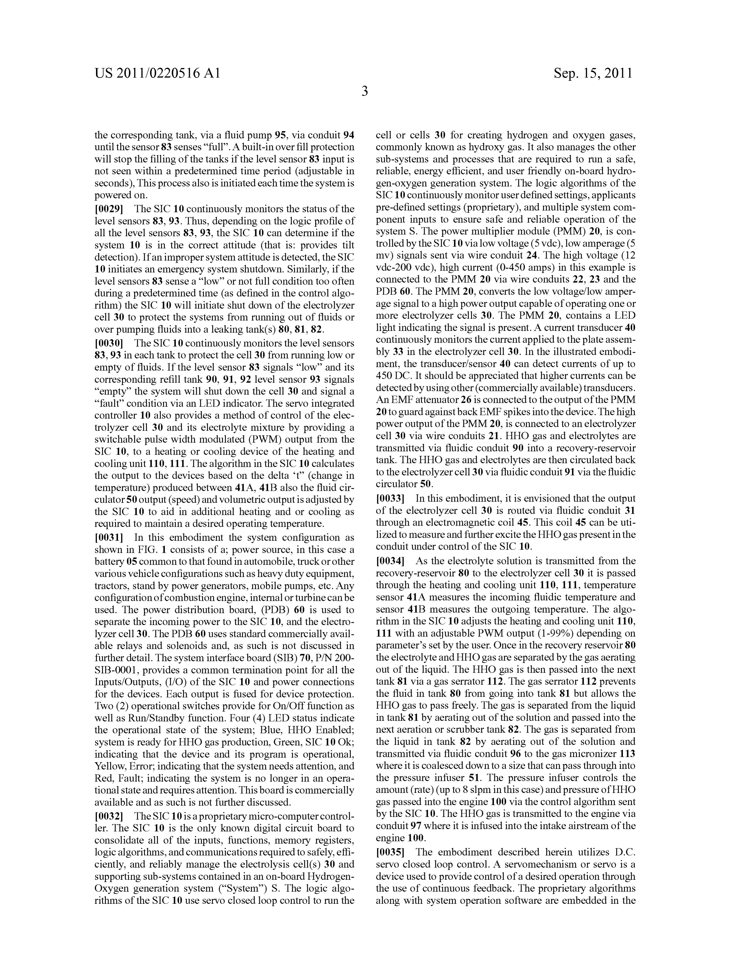
logic algorithms, and communications required to safely, effi 0035. The embodiment described herein utilizes D.C. ciently, and reliably manage the electrolysis cell(s) 30 and servo closed loop control. A servomechanism or servo is a Supporting Sub-systems contained in an on-board Hydrogen device used to provide control of a desired operation through Oxygen generation system (“System’’) S. The logic algo the use of continuous feedback. The proprietary algorithms rithms of the SIC 10 use servo closed loop control to run the along with system operation software are embedded in the
Page 6
US 2011/022051.6 A1 Sep. 15, 2011
“HHO Controller Rev. 1.0 board, name branded as: source as in a D.C. battery, or rectified A.C. source. HYDRO-MAXXTM Servo integrated controller, a multi chip, Frequency, 1.97 hz-1499 hz in this case, or up to 22 khz microprocessor controlled device. This controller is available maximum.
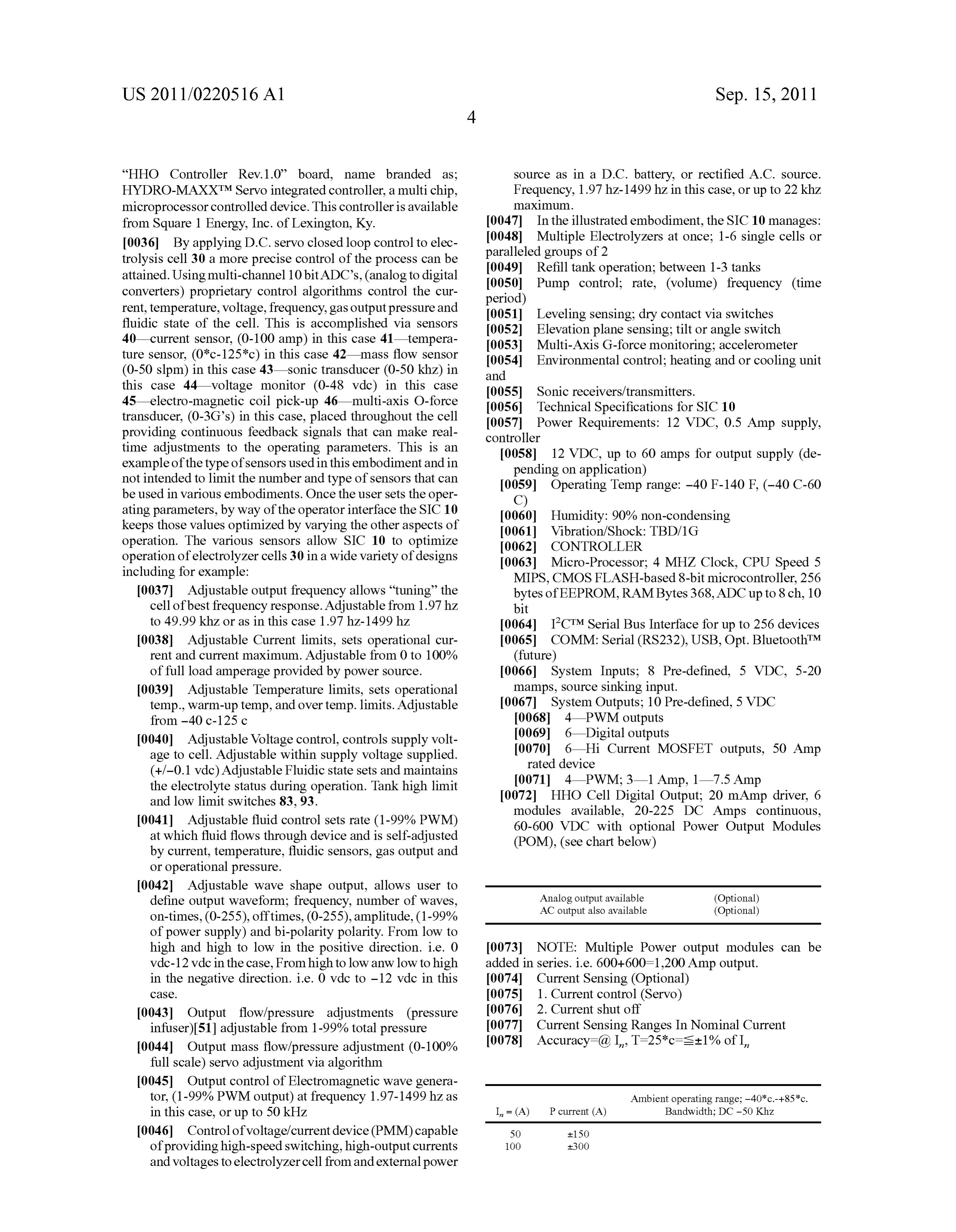
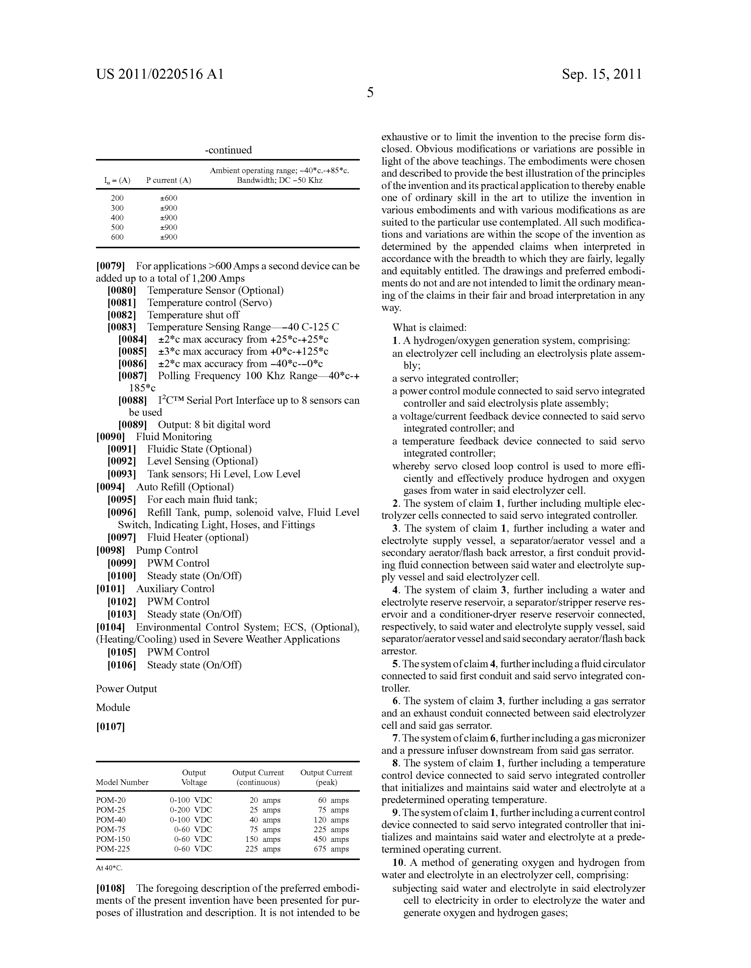
from Square 1 Energy, Inc. of Lexington, Ky. 0047. In the illustrated embodiment, the SIC 10 manages: 0036 By applying D.C. servo closed loop control to elec 0048 Multiple Electrolyzers at once: 1-6 single cells or trolysis cell 30 a more precise control of the process can be paralleled groups of 2 attained. Using multi-channel 10 bit ADC's, (analog to digital 0049 Refill tank operation; between 1-3 tanks converters) proprietary control algorithms control the cur 0050 Pump control; rate, (volume) frequency (time period) rent, temperature, Voltage, frequency, gas output pressure and 0051 Leveling sensing: dry contact via switches fluidic state of the cell. This is accomplished via sensors 0.052 Elevation plane sensing: tilt or angle switch 40—current sensor, (0-100 amp) in this case 41—tempera 0053. Multi-Axis G-force monitoring; accelerometer ture sensor, (0*c-125*c) in this case 42 mass flow sensor 0054 Environmental control; heating and or cooling unit (0-50 slpm) in this case 43—sonic transducer (0-50 khz) in and this case 44 voltage monitor (0-48 Vdc) in this case 0055 Sonic receivers/transmitters. 45—electro-magnetic coil pick-up 46—multi-axis O-force 0056 Technical Specifications for SIC 10 transducer, (0-3G's) in this case, placed throughout the cell 0057 Power Requirements: 12 VDC, 0.5 Amp supply, providing continuous feedback signals that can make real controller time adjustments to the operating parameters. This is an 0.058 12 VDC, up to 60 amps for output supply (de example of the type of sensors used in this embodiment and in pending on application) not intended to limit the number and type of sensors that can 0059 Operating Temp range: -40 F-140 F (-40 C-60 be used in various embodiments. Once the user sets the oper C) ating parameters, by way of the operator interface the SIC 10 0060 Humidity: 90% non-condensing keeps those values optimized by varying the other aspects of 0061 Vibration/Shock: TBD/1G operation. The various sensors allow SIC 10 to optimize 0062 CONTROLLER operation of electrolyzer cells 30 in a wide variety of designs 0063 Micro-Processor; 4 MHZ Clock, CPU Speed 5 including for example: MIPS, CMOS FLASH-based 8-bit microcontroller, 256 0037 Adjustable output frequency allows “tuning the bytes of EEPROM, RAMBytes 368, ADCup to 8 ch, 10 cell of best frequency response. Adjustable from 1.97 hz bit to 49.99 khz or as in this case 1.97 hz-1499 hz (0.064 ICTM Serial Bus Interface for up to 256 devices 0038. Adjustable Current limits, sets operational cur 0065 COMM: Serial (RS232), USB, Opt. BluetoothTM rent and current maximum. Adjustable from 0 to 100% (future) of full load amperage provided by power source. (0.066 System Inputs: 8 Pre-defined, 5 VDC, 5-20 0039. Adjustable Temperature limits, sets operational mamps, Source sinking input. temp., warm-up temp, and over temp. limits. Adjustable 0067 System Outputs; 10 Pre-defined, 5 VDC from -40 c-125 c 0068 4 PWM outputs 0040 Adjustable Voltage control, controls supply volt 0069. 6- Digital outputs age to cell. Adjustable within Supply Voltage Supplied. (0070) 6 Hi Current MOSFET outputs, 50 Amp rated device (+/-0.1 vac) Adjustable Fluidic state sets and maintains (0071 4 PWM; 3–1 Amp, 1–7.5 Amp the electrolyte status during operation. Tank high limit and low limit switches 83,93. 0072 HHO Cell Digital Output: 20 mAmp driver, 6 0041 Adjustable fluid control sets rate (1-99% PWM) modules available, 20-225 DC Amps continuous, at which fluid flows through device and is self-adjusted 60-600 VDC with optional Power Output Modules by current, temperature, fluidic sensors, gas output and (POM), (see chart below) or operational pressure.
0042 Adjustable wave shape output, allows user to define output waveform; frequency, number of waves, Analog output available (Optional) AC output also available (Optional)
of power supply) and bi-polarity polarity. From low to high and high to low in the positive direction. i.e. 0 (0073 NOTE: Multiple Power output modules can be vdc-12 vac in the case, From high to low anw low to high added in series. i.e. 600+600–1,200 Amp output. in the negative direction. i.e. 0 vac to -12 vac in this 0074 Current Sensing (Optional) CaSC. (0075 1. Current control (Servo) 0043. Output flow/pressure adjustments (pressure 0076 2. Current shut off infuser).51 adjustable from 1-99% total pressure 0077 Current Sensing Ranges. In Nominal Current 0044) Output mass flow/pressure adjustment (0-100% 0078. Accuracy=(a) I., T=25*c=s+1% of I. full scale) servo adjustment via algorithm 0045. Output control of Electromagnetic wave genera tor, (1-99% PWM output) at frequency 1.97-1499 hzas Ambient operating range: -40*c.---85*c. in this case, or up to 50 kHz I = (A) P current (A) Bandwidth; DC-50 Khz 0046 Control of voltage/current device (PMM) capable 50 150 of providing high-speed Switching, high-output currents 1OO 3OO and Voltages to electrolyzer cell from and external power
Page 7
US 2011/022051.6 A1 Sep. 15, 2011
exhaustive or to limit the invention to the precise form dis -continued closed. Obvious modifications or variations are possible in light of the above teachings. The embodiments were chosen
Ambient operating range: -40*c.---85*c. and described to provide the best illustration of the principles
I = (A) P current (A) Bandwidth; DC-50 Khz of the invention and its practical application to thereby enable 200 6OO one of ordinary skill in the art to utilize the invention in 300 900 various embodiments and with various modifications as are
500 900 Suited to the particular use contemplated. All Such modifica 600 900 tions and variations are within the scope of the invention as determined by the appended claims when interpreted in 007.9 For applications >600 Amps a second device can be accordance with the breadth to which they are fairly, legally and equitably entitled. The drawings and preferred embodi added up to a total of 1,200 Amps ments do not and are not intended to limit the ordinary mean 0080 Temperature Sensor (Optional) ing of the claims in their fair and broad interpretation in any I0081 Temperature control (Servo) way.
I0082) Temperature shut off
I0083 Temperature Sensing Range -40 C-125C What is claimed:
I0084 +2*c max accuracy from +25*c-+25*c 1. A hydrogen/oxygen generation system, comprising: I0085 +3*c max accuracy from +0*c-+125*c an electrolyzer cell including an electrolysis plate assem I0086) +2*c max accuracy from -40*c--0*c bly:
I0087 Polling Frequency 100 Khz Range 40*c-+ a servo integrated controller;
185*c a power control module connected to said servo integrated I0088 ICTM Serial Port Interface up to 8 sensors can controller and said electrolysis plate assembly: be used a Voltage/current feedback device connected to said servo I0089 Output: 8 bit digital word integrated controller; and 0090 Fluid Monitoring a temperature feedback device connected to said servo (0091 Fluidic State (Optional) integrated controller;
0092 Level Sensing (Optional) whereby servo closed loop control is used to more effi 0093 Tank sensors: Hi Level, Low Level ciently and effectively produce hydrogen and oxygen 0094) Auto Refill (Optional) gases from water in said electrolyzer cell. 0095 For each main fluid tank; 2. The system of claim 1, further including multiple elec 0096 Refill Tank, pump, solenoid valve, Fluid Level trolyzer cells connected to said servo integrated controller. Switch, Indicating Light, Hoses, and Fittings 3. The system of claim 1, further including a water and (0097. Fluid Heater (optional) electrolyte Supply vessel, a separator/aerator vessel and a 0098 Pump Control secondary aerator/flash back arrestor, a first conduit provid 0099 PWM Control ing fluid connection between said water and electrolyte Sup 0100 Steady state (On/Off) ply vessel and said electrolyzer cell. 0101 Auxiliary Control 4. The system of claim 3, further including a water and 01.02 PWM Control electrolyte reserve reservoir, a separator/stripper reserve res (0103 Steady state (On/Off) ervoir and a conditioner-dryer reserve reservoir connected, 0104 Environmental Control System; ECS, (Optional), respectively, to said water and electrolyte Supply vessel, said (Heating/Cooling) used in Severe Weather Applications separator/aerator vessel and said secondary aerator/flashback 01.05 PWM Control arrestOr.
0106 Steady state (On/Off) 5. The system of claim 4, further including a fluid circulator connected to said first conduit and said servo integrated con
Power Output troller.
Module 6. The system of claim 3, further including a gas serrator and an exhaust conduit connected between said electrolyzer 01.07 cell and said gas serrator.
7. The system of claim 6, further including a gas micronizer and a pressure infuser downstream from said gas serrator.
8. The system of claim 1, further including a temperature
Output Output Current Output Current control device connected to said servo integrated controller Model Number Voltage (continuous) (peak) that initializes and maintains said water and electrolyte at a
POM-2O O-100 VDC 20 amps 60 amps predetermined operating temperature. POM-2S O-200 VDC 25 amps 75 amps 9. The system of claim 1, further including a current control POM-40 O-100 VDC 40 amps 120 amps
POM-75 O-60 VDC 75 amps 225 amps device connected to said servo integrated controller that ini POM-1SO O-60 VDC 150 amps 450 amps tializes and maintains said water and electrolyte at a prede POM-225 O-60 VDC 225 amps 675 amps termined operating current.
At 40*C. 10. A method of generating oxygen and hydrogen from water and electrolyte in an electrolyzer cell, comprising:
0108. The foregoing description of the preferred embodi Subjecting said water and electrolyte in said electrolyzer ments of the present invention have been presented for pur cell to electricity in order to electrolyze the water and poses of illustration and description. It is not intended to be generate oxygen and hydrogen gases;
Page 8
US 2011/022051.6 A1 Sep. 15, 2011
monitoring the electrolysis process with a Voltage/current 14. The method of claim 11, including maintaining a feedback device and a temperature feedback device both desired level of water and electrolyte in a water and electro connected to a servo integrated controller, and lyte Supply vessel during said electrolysis process. using servo closed loop continuous feedback to control 15. The method of claim 14, including maintaining a operating parameters including (a) frequency, current desired level of separator/stripper in a separator/aerator ves and Voltage of electricity and (b) temperature of said sel during said electrolysis process.
water and electrolyte. 16. The method of claim 15, including maintaining a 11. The method of claim 10, including maintaining the desired level of conditioner-dryer in a secondary aerator/flash back arrestor.
temperature of said water and electrolyte within a predeter 17. The method of claim 16, including initializing said mined range during the electrolysis process. electrolysis process by bringing levels of (1) water and elec 12. The method of claim 11, further including initializing trolyte in said water and electrolyte Supply vessel, (2) sepa said electrolysis process by bringing the temperature of said rator/stripper in said separator/aerator vessel and (3) condi water and electrolyte within said predetermined range before tioner-dryer in said secondary aerator/flash back arrestor to beginning the electrolysis process. desired levels before beginning the electrolysis process. 13. The method of claim 11, further including soft-starting 18. The method of claim 17, including circulating water said electrolysis process by varying at least one of frequency, and electrolyte from said water and electrolyte supply vessel current, Voltage and wave form of said electricity initially to said electrolytic cell at a predetermined rate once a desired applied to said water and electrolyte so as to prevent damage operational temperature has been reached. to any coated surface of electric plates of said electrolyzer cell that might otherwise becaused by large current spikes. c c c c c
Provenance
- Collection
- Patents citing this work
- Current assignee
- EVERGREEN FIRST START Inc
- Pages
- 8
- Method
- pdftotext (the PDF's own text layer) + pdftoppm 300dpi page scans
- Patent office record
- patents.google.com →
- Source
- Google Patents citing-documents table
- Inventors
- Timm J. Finfrock; James D. Hill; David A. Bateman, JR.
- Published
- 2011-09-15
- Transcribed from
- patentimages.storage.googleapis.com →