patent · US4206029
Detonating gas generator
3 June 1980
Page 1 — bibliographic record
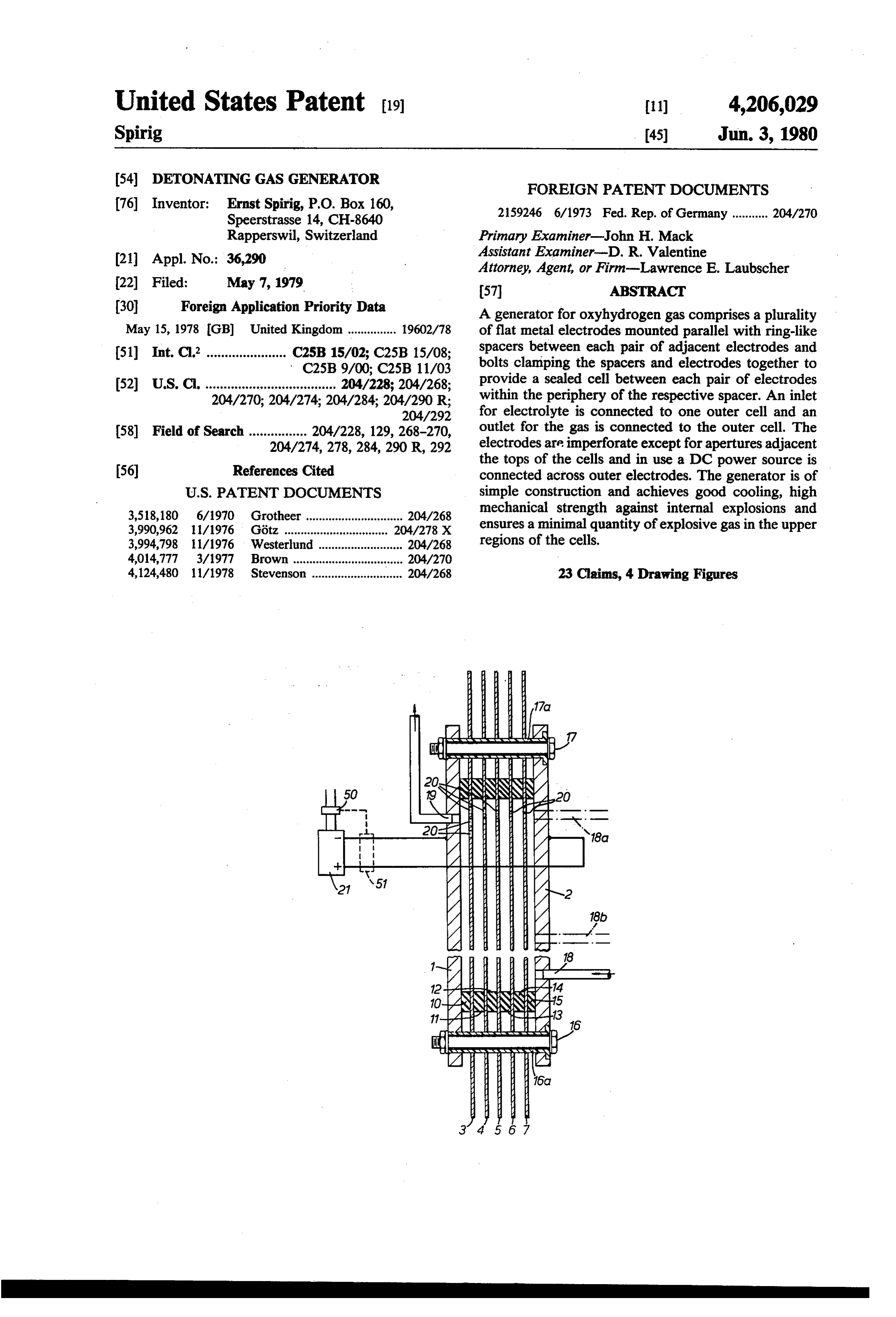
United States Patent (19) 11) 4,206,029 Spirig 45) Jun. 3, 1980 (54) DETONATING GAS GENERATOR FOREIGN PATENT DOCUMENTS 76 Inventor: Ernst Spirig, P.O. Box 160, 2159246 6/1973 Fed. Rep. of Germany ........... 204/270 Speerstrasse 14, CH-8640
Rapperswil, Switzerland Primary Examiner-John H. Mack (21) Appl. No.: 36,290 Assistant Examiner-D. R. Valentine Attorney, Agent, or Firm-Lawrence E. Laubscher 22 Filed: May 7, 1979 57 ABSTRACT (30) Foreign Application Priority Data A generator for oxyhydrogen gas comprises a plurality May 15, 1978 GB) United Kingdom ............... 19602/78 of flat metal electrodes mounted parallel with ring-like (51) Int. C.’...................... C25B 15/02; C25B 15/08; spacers between each pair of adjacent electrodes and C25B 9/00; C25B 11/03 bolts clamping the spacers and electrodes together to 52 U.S. C. .................................... 204/228; 204/268; provide a sealed cell between each pair of electrodes 204/270; 204/274; 204/284; 204/290 R; within the periphery of the respective spacer. An inlet 204/292 for electrolyte is connected to one outer cell and an 58) Field of Search ................ 204/228, 129, 268-270, outlet for the gas is connected to the outer cell. The 204/274, 278, 284, 290 R, 292 electrodes are imperforate except for apertures adjacent the tops of the cells and in use a DC power source is (56) References Cited connected across outer electrodes. The generator is of
3,518,180 6/1970 Grotheer .............................. 204/268 mechanical strength against internal explosions and 3,990,962 11/1976 Götz .............. ... 204/278 X ensures a minimal quantity of explosive gas in the upper 3,994,798 11/1976 Westerlund .......................... 204/268 regions of the cells.
4,014,777 3/1977 Brown ........... ... 204/270 4,124,480 11/1978 Stevenson ............................ 204/268 23 Claims, 4 Drawing Figures
Page 2
Drawing sheet — no readable text.
Page 3
Drawing sheet — no readable text.
Page 4
trodes together. The bolts are spaced apart around the
DETONATING GAS GENERATOR periphery of the cells (outwardly of the spacers) and each bolt extends through bores formed through the
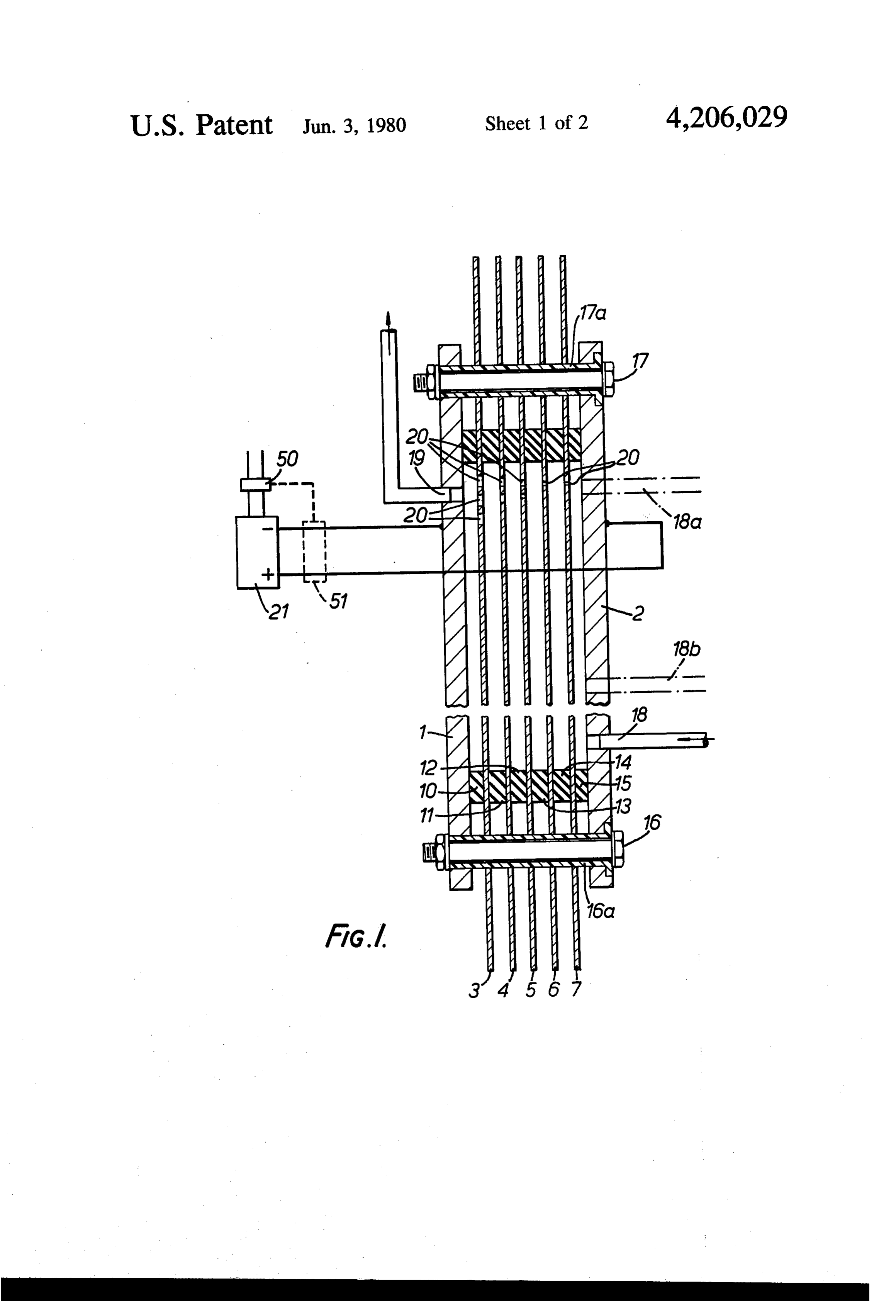
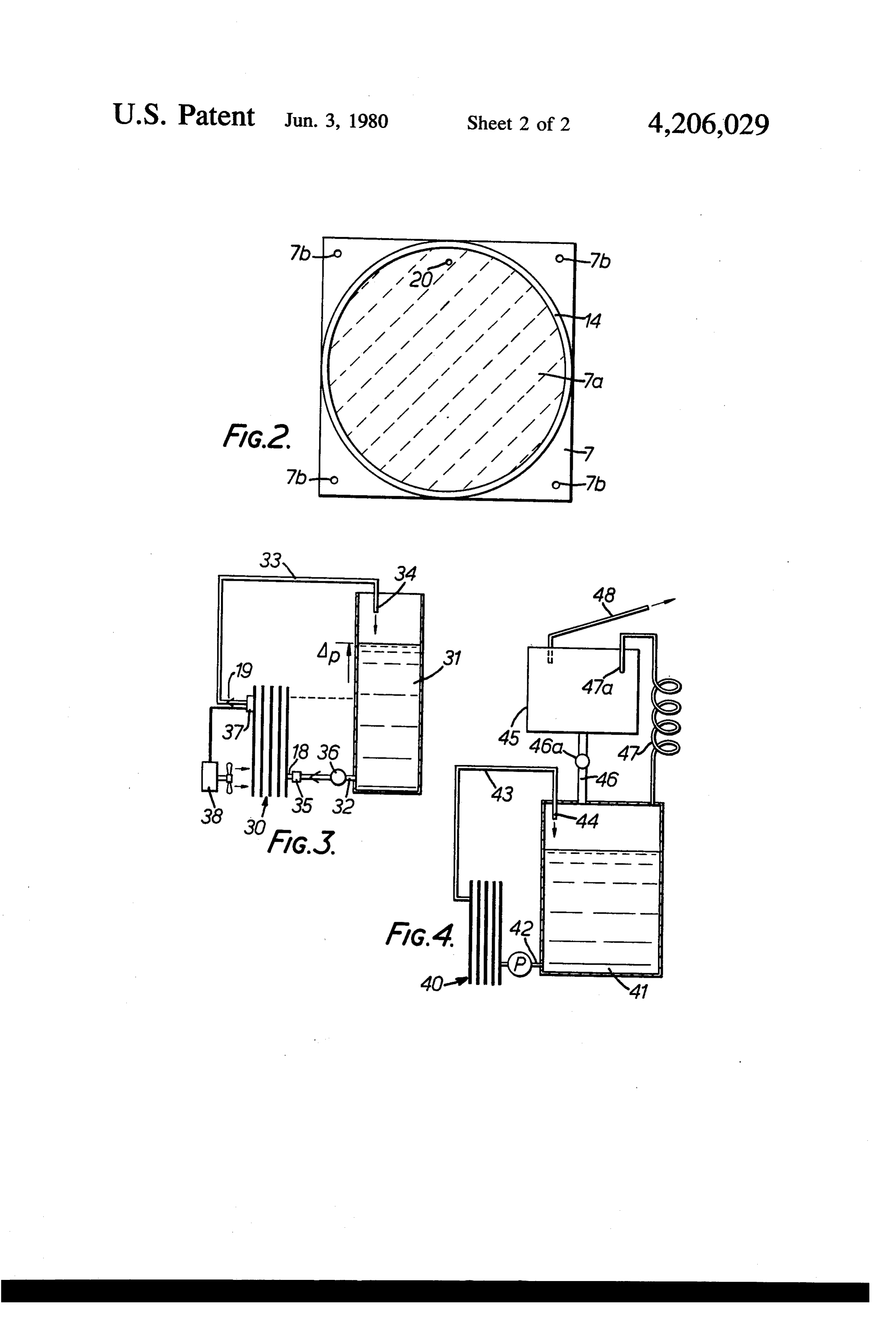
This invention is an improvement on the apparatus electrodes. Two of the bolts 16,17 are shown and elec described and claimed in my British Pat. No. 1,519,679 trical insulation 16a, 17a is provided to insulate the (U.S. Pat. No. 4,113,601) and aims at a simplified con metal bolts from the individual electrodes, struction which nevertheless achieves improved cool The clamping means serves to clamp the electrodes ing, high mechanical strength against any internal ex and spacers together and in particular to compress the plosions and minimal volume of explosive gas mixture spacers, thus ensuring an effective peripheral seal be in the upper regions of the cells. 10 tween each spacer and the two electrodes between In accordance with the invention, there is provided a which it is clamped. The surfaces of the electrodes may detonating gas generator, comprising a plurality of flat be sandblasted to increase the effective surface area for metal electrodes mounted parallel to each other with a the electrolysis process and to improve the strength of ring-like spacer disposed between each pair of adjacent the spacers against any excessive pressures which may electrodes, means for clamping the plurality of elec 15 develop within the individual cells. trodes and spacers together so as to provide a sealed cell An inlet aperture 18 for electrolyte is formed through between each pair of adjacent electrodes and within the the outer electrode 2, adjacent the bottom of the cell periphery of the respective spacer, an inlet connected or which is formed between electrodes 7 and 2. Alterna connectable to a source of electrolyte and formed tively, this inlet aperture may be provided adjacent the through one outer electrode and into the respective cell, 20 top of its cell, or at an intermediate position, as indicated an outlet for detonating gas formed through the other in dotted lines at 18a, 18b respectively. An outlet aper outer electrode adjacent the top of the respective cell, ture 19 for oxyhydrogen gas, is formed through the and apertures formed in the intervening electrodes adja outer electrode 1, adjacent the top of the cell formed cent the tops of the respective cells, the intervening between electrodes 1 and 3. A series of apertures 20 is electrodes being otherwise imperforate at least within 25 provided in the intervening electrodes, adjacent the top the cells, and the outer electrodes being connected or of the respective cells for the transfer of the generated connectable to respective poles of a DC electrical sup oxyhydrogen foam from the successive cells and ply. towards the outlet 19, in the manner described in my Embodiment of this invention will now be described, British Pat. No. 1,519,679. The electrodes 1-7 are other by way of examples only, with reference to the accom 30 wise imperforate. In use, the outer electrodes 1,2 are panying drawings, in which: . connected to the negative and positive poles, respec FIG. 1 is a vertical section through one embodiment tively, of a DC electrical supply 21. Initially, electrolyte of detonating gas generator, the section being in a plane (basically water) fills the cells to the level of the aper perpendicular to the plate electrodes; tures 20 but, in use, the gas which is produced fills the FIG. 2 is a vertical section through a modified gener 35 upper regions of the cells and depressed the level of ator, the section being parallel to the plate electrodes; electrolyte. Gas leaves the cells through the outlet 19 FIG. 3 is a diagram of a gas generator used with an and fresh electrolyte enters continuously through inlet electrolyte reservoir; and 18,18a or 18b.
FIG. 4 is a diagram of a gas generator used with an All electrodes are simple and inexpensive to produce electrolyte reservoir and a trapping means for condens and can be produced by cutting or stamping from metal ing water vapour entrained with the gas which is pro sheet. The seals provided by the spacers are simple and duced by the generator. effective and the spacers are simple to form from suit The generator shown in FIG. 1 comprises a plurality able sheet material. Also, effective cooling is achieved of electrodes, comprising two outer electrodes 1,2 and a as a result of the electrodes extending substantially be plurality of intervening electrodes 3,4,5,6,7 an electroly 45 yond the spacers and into the surrounding air. The sis cell being formed between each adjacent pair of distance between electrodes is easily selected by select electrodes. Each of the electrodes is flat and rectangular ing spacers of the appropriate thickness. and is stamped from a flat sheet of metal. Each elec The generator has high mechanical strength against trode is mounted parallel to the other and it will be any internal explosions which may occur by accident. noted that the outer electrodes 1,2 are formed from Thus, the clamping bolts 16,17 provide strength against substantially thicker sheet metal than the intervening force acting perpendicular to the planes of the elec electrodes. In the example shown, the intervening elec trodes, whilst forces acting parallel to the planes of the trodes are larger in both height and width and project electrodes are withstood by the spacers being com beyond the edges of the outer electrodes in both verti pressed between the electrodes. There is no need for a cal directions and both horizontal directions. 55 pressure vessel in which to place the apparatus. It is Adjacent pairs of electrodes are spaced apart bygen possible to work with higher pressures than hitherto erally ring-shaped spacers 10,11,12,13,14,15 of resilient and this reduces the losses in the electrolyte because the material. These spacers may be circular rings or rectan electrical resistance of the electrolyte, for the same gular-shaped frames and are stamped from sheet mate amount of gas bubbles, is lower at increased pressure rial. This material may comprise rubber but must be because the individual bubbles are smaller and therefore resistant to the alkaline solutions forming the electro have less influence on the current path between adja lyte. It will be noted that the spacers are aligned with cent electrodes.
each other, that the intervening spaces are aligned with The design is appropriate for very small electrolysis each other and that the outer electrodes 1,2 are aligned cells, which have the advantage of reducing current with each other. .. . 65 heating because of the smaller physical distance be The electrodes and spacers are clamped together by tween cells. Therefore, a practical apparatus may com appropriate means. In the example shown, these means prise a large number of cells and make use of a rectified comprise a plurality of bolts clamping the outer elec 220 volts A.C. supply.
Page 5
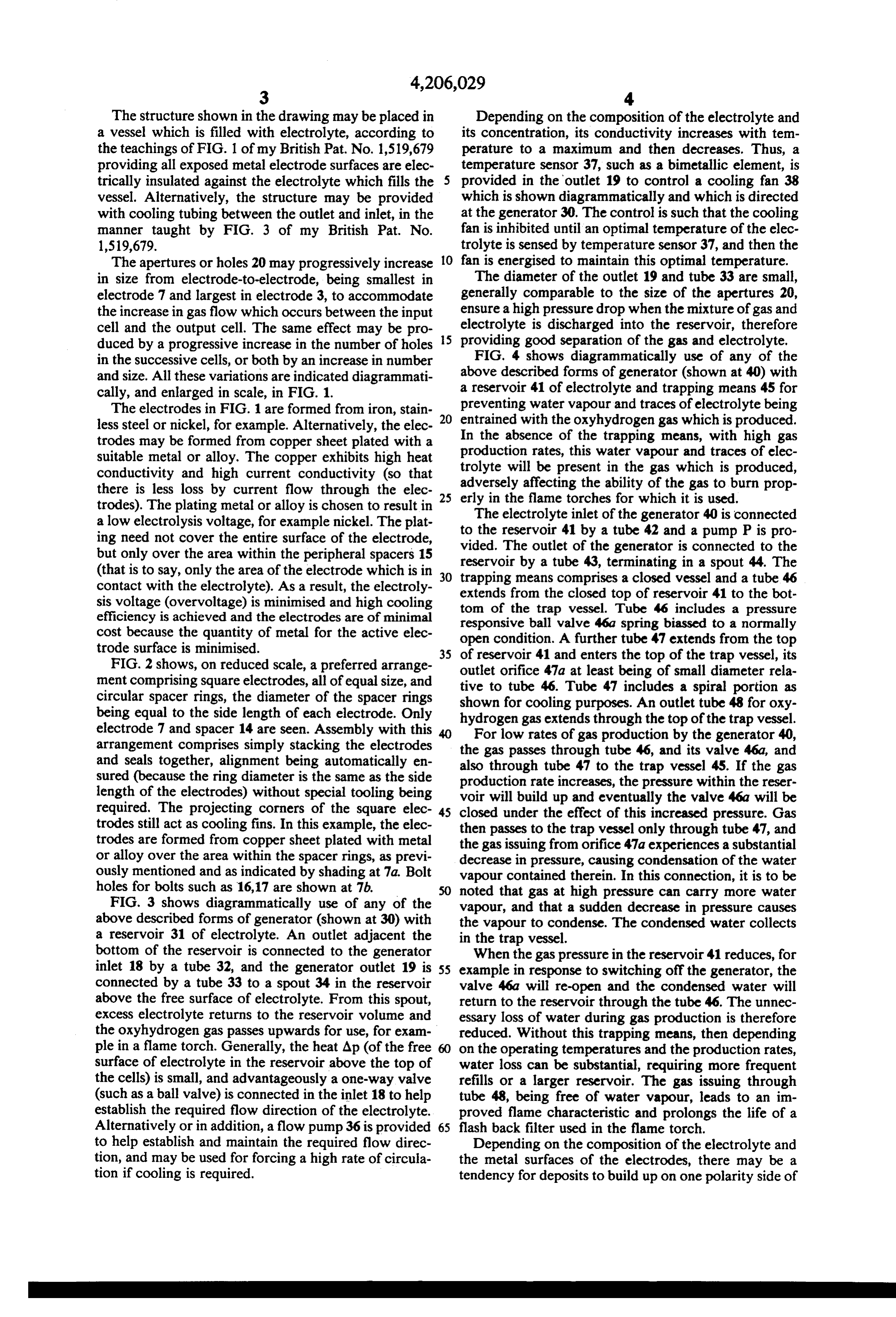
The structure shown in the drawing may be placed in Depending on the composition of the electrolyte and a vessel which is filled with electrolyte, according to its concentration, its conductivity increases with tem the teachings of FIG. 1 of my British Pat. No. 1,519,679 perature to a maximum and then decreases. Thus, a providing all exposed metal electrode surfaces are elec temperature sensor 37, such as a bimetallic element, is trically insulated against the electrolyte which fills the provided in the outlet 19 to control a cooling fan 38 vessel. Alternatively, the structure may be provided which is shown diagrammatically and which is directed with cooling tubing between the outlet and inlet, in the at the generator 30. The control is such that the cooling manner taught by FIG. 3 of my British Pat. No. fan is inhibited until an optimal temperature of the elec 1,519,679. trolyte is sensed by temperature sensor 37, and then the The apertures or holes 20 may progressively increase O fan is energised to maintain this optimal temperature. in size from electrode-to-electrode, being smallest in The diameter of the outlet 19 and tube 33 are small, electrode 7 and largest in electrode 3, to accommodate generally comparable to the size of the apertures 20, the increase in gas flow which occurs between the input ensure a high pressure drop when the mixture of gas and cell and the output cell. The same effect may be pro 5 electrolyte is discharged into the reservoir, therefore providing good separation of the gas and electrolyte.
duced by a progressive increase in the number of holes in the successive cells, or both by an increase in number FIG. 4 shows diagrammatically use of any of the and size. All these variations are indicated diagrammati above described forms of generator (shown at 40) with cally, and enlarged in scale, in FIG. 1. a reservoir 41 of electrolyte and trapping means 45 for The electrodes in FIG. 1 are formed from iron, stain 20 preventing water vapour and traces of electrolyte being less steel or nickel, for example. Alternatively, the elec entrained with the oxyhydrogen gas which is produced. In the absence of the trapping means, with high gas trodes may be formed from copper sheet plated with a production suitable metal or alloy. The copper exhibits high heat trolyte will rates, this water vapour and traces of elec be present in the gas which is produced, conductivity and high current conductivity (so that adversely there is less loss by current flow through the elec 25 erly in theaffectingflame the ability of the gas to burn prop torches for which it is used.
trodes). The plating metal or alloy is chosen to result in a low electrolysis voltage, for example nickel. The plat to The electrolyte inlet of the generator 40 is connected the reservoir 41 by a tube 42 and a pump P is pro ing need not cover the entire surface of the electrode, vided. The outlet of the generator is connected to the but only over the area within the peripheral spacers 15 reservoir by a tube 43, terminating in a spout 44. The (that is to say, only the area of the electrode which is in 30 trapping means contact with the electrolyte). As a result, the electroly extends from thecomprises closed top a closed vessel and a tube 46 of reservoir 41 to the bot sis voltage (overvoltage) is minimised and high cooling tom of the trap vessel. Tube 46 includes a pressure efficiency is achieved and the electrodes are of minimal responsive ball valve 46a spring biassed to a normally cost because the quantity of metal for the active elec open condition. A further tube 47 extends from the top trode surface is minimised. 35 of reservoir 41 and enters the top of the trap vessel, its FIG. 2 shows, on reduced scale, a preferred arrange ment comprising square electrodes, all of equal size, and outlet tive to orifice 47a at least being of small diameter rela tube 46. Tube 47 includes a spiral portion as circular spacer rings, the diameter of the spacer rings shown for cooling purposes. An outlet tube 48 for oxy being equal to the side length of each electrode. Only hydrogen gas extends through the top of the trap vessel. electrode 7 and spacer 14 are seen. Assembly with this For low rates of gas production by the generator 40, arrangement comprises simply stacking the electrodes the gas passes through and Seals together, alignment being automatically en also through tube 47 totube 46, and its valve 46a, and the trap vessel 45. If the gas sured (because the ring diameter is the same as the side production rate increases, the pressure within the reser length of the electrodes) without special tooling being voir will build up and eventually the valve 46a will be required. The projecting corners of the square elec 45 closed under the effect of this increased pressure. Gas trodes still act as cooling fins. In this example, the elec then passes to the trap vessel only through tube 47, and trodes are formed from copper sheet plated with metal the gas issuing from orifice 47a experiences a substantial or alloy over the area within the spacer rings, as previ decrease in pressure, causing condensation of the water ously mentioned and as indicated by shading at 7a. Bolt vapour contained therein. In this connection, it is to be holes for bolts such as 16,17 are shown at 7b. noted that gas at high pressure can carry more water FIG. 3 shows diagrammatically use of any of the vapour, and that a sudden decrease in pressure causes above described forms of generator (shown at 30) with the vapour to condense. The condensed water collects a reservoir 31 of electrolyte. An outlet adjacent the in the trap vessel.
bottom of the reservoir is connected to the generator When the gas pressure in the reservoir 41 reduces, for inlet 18 by a tube 32, and the generator outlet 19 is 55 example in response to switching off the generator, the connected by a tube 33 to a spout 34 in the reservoir valve 46a will re-open and the condensed water will above the free surface of electrolyte. From this spout, return to the reservoir through the tube 46. The unnec excess electrolyte returns to the reservoir volume and essary loss of water during gas production is therefore the oxyhydrogen gas passes upwards for use, for exam reduced. Without this trapping means, then depending ple in a flame torch. Generally, the heat Ap (of the free 60 on the operating temperatures and the production rates, surface of electrolyte in the reservoir above the top of water loss can be substantial, requiring more frequent the cells) is small, and advantageously a one-way valve refills or a larger reservoir. The gas issuing through (such as a ball valve) is connected in the inlet 18 to help tube 48, being free of water vapour, leads to an im establish the required flow direction of the electrolyte. proved flame characteristic and prolongs the life of a Alternatively or in addition, a flow pump 36 is provided 65 flash back filter used in the flame torch. to help establish and maintain the required flow direc Depending on the composition of the electrolyte and tion, and may be used for forcing a high rate of circula the metal surfaces of the electrodes, there may be a tion if cooling is required. tendency for deposits to build up on one polarity side of
Page 6
each electrode. Accordingly, it is proposed to change 8. A detonating gas generator as claimed in any one the polarity of the connections to the DC source 21 of claims 1 to 6, in which the inlet is provided adjacent from time-to-time, for example changing the connec the top of its respective cell.
tions each time the generator is switched off. The de 9. A detonating gas generator as claimed in any of posit built up in one operating period is then eroded in claims 1 to 6, in which the inlet is provided intermediate the next operating period, the deposit being flushed out the top and bottom of its respective cell. of the generator cells by the flow of electrolyte. With 10. A detonating gas generator as claimed in any one small spacings between the electrodes this procedure is of the preceding claims, in which the electrodes are especially helpful to avoid requirements for generator formed from sheet metal.
servicing and cleaning. The change in polarity changes 10 11. A detonating gas generator as claimed in claim 10, the electrodes in each cell at which the oxygen and in which the electrodes comprise any one of iron, stain hydrogen are generated. The direction of flow remains less steel and nickel.
the same, being determined by the hydrostatic pressure 12. A detonating gas generator as claimed in claim 10, produced by reservoir 31 or 41 and present at the inlet in which the electrodes comprise copper plated at least 18. Referring to FIG. 1, an on/off switch 50 in the lines 15 over its area within the adjacent spacers. L from an A.C. supply to the D.C. generator 21 may be 13. A detonating gas generator as claimed in any mechanically or otherwise linked to a changeover preceding claim, in which said apertures progressively switch 51, so that each time the A.C. supply is switched increase in size from the electrode nearest the inlet to on by switch 50, the switch 51 is changed over to re the electrode nearest the outlet.
verse the polarity connections to the gas generator. 20 14. A detonating gas generator as claimed in any I claim: preceding claim, in which said apertures progressively 1. A detonating gas generator, comprising a plurality increase in number from the electrode nearest the inlet of flat metal electrodes mounted parallel to each other to the electrode nearest the outlet. with a ring-like spacer disposed between each pair of 15. Apparatus comprising a detonating gas generator adjacent electrodes, means for clamping the plurality of 25 as claimed in any preceding claim, in combination with electrodes and spacers together so as to provide a sealed a reservoir for containing electrolyte, said inlet commu cell between each pair of adjacent electrodes and within nicating with the reservoir adjacent its bottom and said the periphery of the respective spacer, and inlet con outlet communicating with the reservoir adjacent its nected or connectable to a source of electrolyte and top.
formed through one outer electrode and into the respec 30 16. Apparatus as claimed in claim 15, comprising a tive cell, an outlet for detonating gas formed through one way valve disposed in said inlet or in a tube thereto the other outer electrode adjacent the top of the respec from said reservoir.
tive cell, and apertures formed in the intervening elec 17. Apparatus as claimed in claim 15 comprising a trodes adjacent the tops of the respective cells, the pump disposed in a tube from said reservoir to said inlet. intervening electrodes being otherwise imperforate at 35 18. Apparatus as claimed in any one of claims 15 to least within the cells, and the outer electrodes being 17, comprising a temperature sensor arranged to ener connected or connectable to respective poles of a DC gise a cooling fan for said generator when the generator electrical supply. is above a predetermined operating temperature. 2. A detonating gas generator as claimed in claim 1, in 19. Apparatus as claimed in any one of claims 15 to which the spacers comprise resilient material. 18, further comprising trapping means for condensing 3. A detonating gas generator as claimed in claim 1 or water vapour from the gas produced by the generator. 2, in which the spacers are circular rings of equal diame 20. Apparatus as claimed in claim 19, comprising a tes.
trap vessel and a constricted tube passing from the res 4. A detonating gas generator as claimed in claim3, in ervoir, to the trap vessel, so that the gas is suddenly which the electrodes comprise square plates of equal 45 reduced in pressure as it enters the trap vessel. side lengths which, side lengths are equal to the circular 21. Apparatus as claimed in claim 20, in which said ring diameters. tube includes a helical section for cooling. 5. A detonating gas generator as claimed in any pre 22. Apparatus as claimed in claim 20 or 21, further ceding claim, in which said clamping means comprises a comprising a second tube passing from the reservoir to plurality of bolts spaced around the periphery of the 50 the trap vessel to pass gas to the trap vessel, said second cells, each bolt extending through all electrodes out tube including a pressure responsive valve which closes wardly of the spacers. the tube when the gas pressure in the reservoir is above 6. A detonating gas generator as claimed in claim 5, in a predetermined value.
which the bolts comprise metal and further comprising 23. A detonating gas generator or apparatus as insulation means for insulating the metal bolts from the 55 claimed in any preceding claim, comprising means for individual electrodes. reversing the polarity of the connections of the D.C. 7. A detonating gas generator as claimed in any pre supply to the outer electrodes each time the generator is ceding claim, in which the inlet is provided adjacent the used.
bottom of its respective cell. k k :k k sk
Provenance
- Collection
- Cited prior art
- Original PDF
- patentimages.storage.googleapis.com →
- Filed
- 1979-05-07
- Pages
- 6
- Method
- pdftotext (the PDF's own text layer) + pdftoppm 300dpi page scans
- Source
- Google Patents bibliographic record
- Granted
- 1980-06-03
- Inventors
- Ernst Spirig
- Transcribed from
- patentimages.storage.googleapis.com →