patent · US3957603
Electrolytic gold recovery and separation process
18 May 1976
Page 1 — bibliographic record
United States Patent (19) (11 3,957,603 Rhodes (45) May 18, 1976 54 ELECTROLYTIC GOLD RECOVERY AND 898,785 9/1908 Ruthenburg........................ 204/260 SEPARATION PROCESS 3,673,061 6/1972 Kruesi............................. 204/105 R 3,736,238 5/1973 Kruesi et al..................... 204/105 R 75 Inventor: William A. Rhodes, Phoenix, Ariz.
73 Assignee: Electromet, Inc., Phoenix, Ariz. Primary Examiner-R. L. Andrews Attorney, Agent, or Firm-Warren F. B. Lindsley
(21) Appl. No.: 479,284 57 ABSTRACT A new and effective electrochemical process for the (52) U.S. Cl. ................................................ 204/111 extraction of gold, silver and other precious metals 5ll Int. Cl............................................. C25C 1/20 from low-yield ores containing relatively large quanti 58 Field of Search............................. 204/260, 111 ties of other non-precious metals wherein a novel elec trolytic dissolution cell is provided for the controlled 56) References Cited production and efficient utilization of chlorine as a UNITED STATES PATENTS solubilizing agent for the removal of the precious met als from the ore bodies.
351,576 0/1886 Cassel................................. 20411 1 568,741 10/1896 Cassel................................. 204/111 16 Claims, 6 Drawing Figures
Page 2
Drawing sheet — no readable text.
Page 3
Drawing sheet — no readable text.
Page 4
Drawing sheet — no readable text.
Page 5
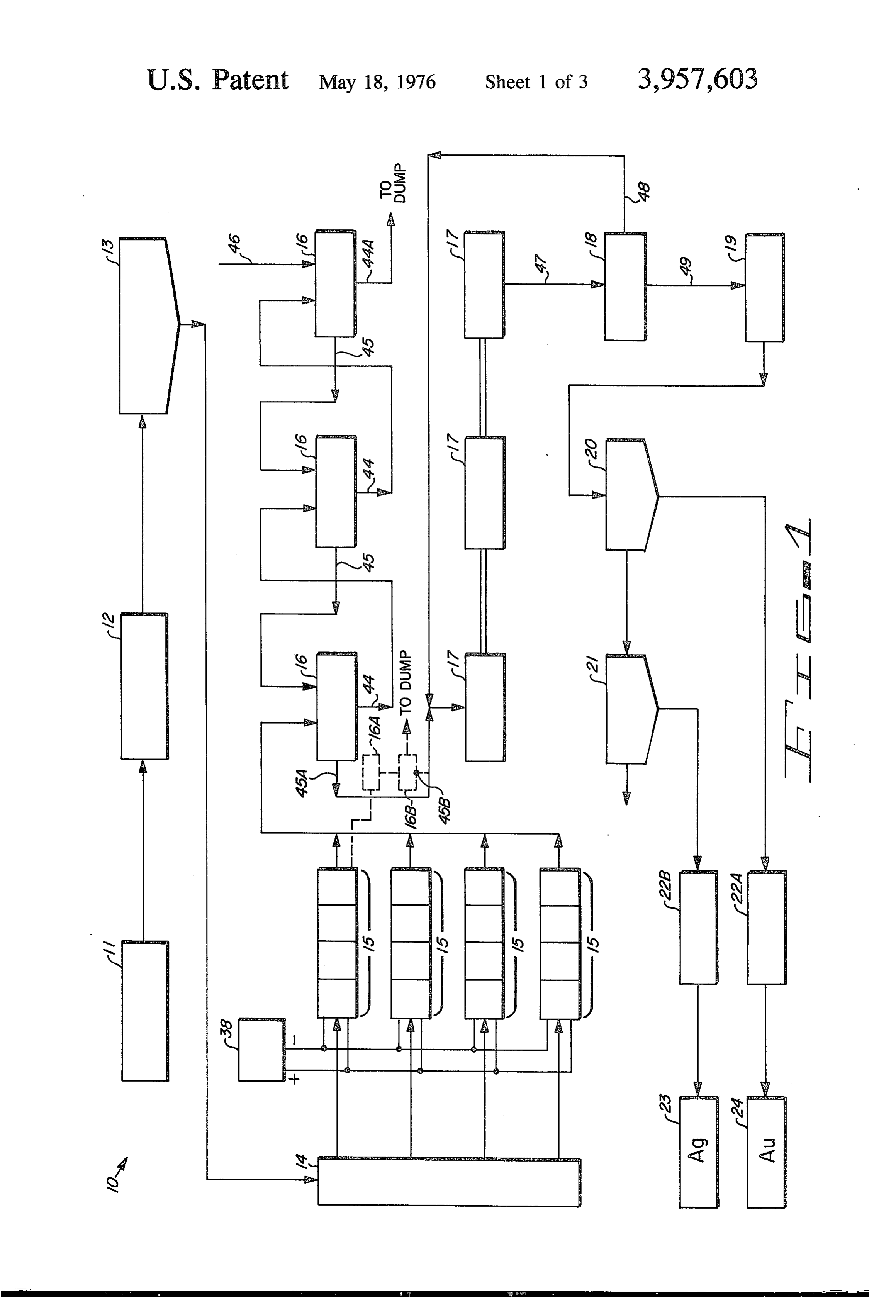
FIG. 1 is a flow sheet illustrating the successive steps
ELECTROLYTIC GOLD RECOVERY AND comprising the electrochemical process and involving SEPARATION PROCESS means and equipment embodying the invention.
BACKGROUND OF THE INVENTION
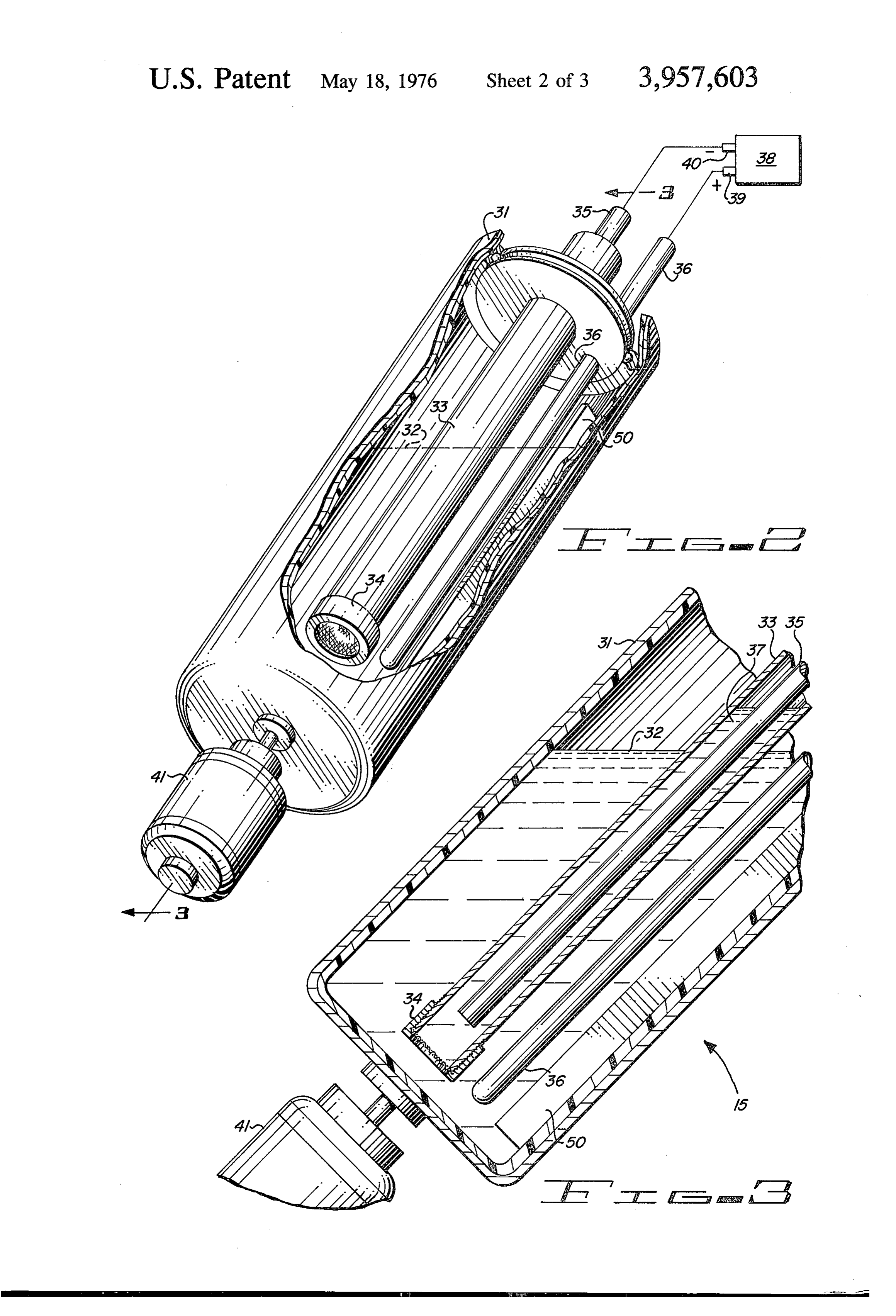
FIG. 2 is a perspective view partially broken away of a dissolution cell developed for this process and consti
Throughout recorded history gold has consistently tuting one of a number of ways of implementing the been one of the most important and most sought-after process herein disclosed.
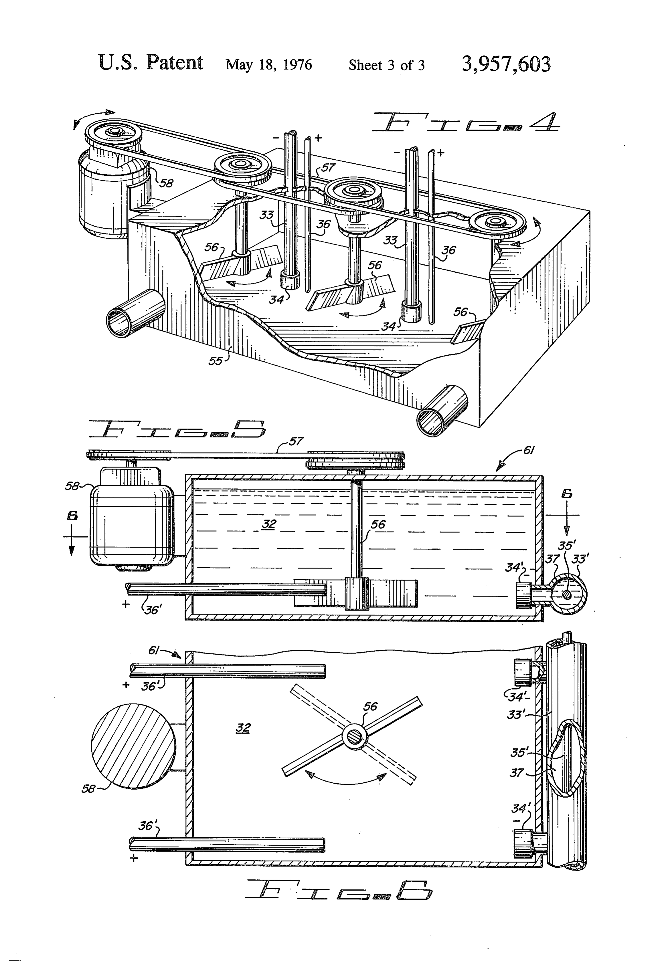
minerals known to man. It has been employed for thou FIG. 3 is an enlarged partial cross sectional view of sands of years as a form of currency, it has been fash O the structure shown in FIG. 2 illustrating more detail of ioned into ornaments and jewelry and it has found the anode-cathode arrangement.
important industrial applications as well. In very recent FIG. 4 is a partial broken away perspective view of a times the growing scarcity of gold and its importance in modification of the dissolution cell shown in FIG. 2. monetary terms have caused gold prices to skyrocket FIGS. 5 and 6 illustrate end and top views of a further throughout the world. modification of the dissolution cell shown in FIGS. 1-4. The recovery of gold from its ores is commonly ac 15 DESCRIPTION OF THE PREFERRED complished by one of a number of methods including EMBODIMENT flotation, amalgamation with mercury or by the cya nide process. Where the gold content of the ore is high, Referring more particularly to the drawing by char smelting is economical; the cyanide process is em acters of reference, FIG. 1 disclosed the improved ployed for the lower concentrations of gold. Where the 20 electrochemical recovery system 10 comprising an ore gold content is very low relative to the amount of other storage facility 11, a ball mill 12, a classifier 13, a spe metals contained, these processes all become ineffi cial distribution box 14, a series of dissolution cells 15, cient and expensive. rubber-linked thickeners 16, settling tanks 17, thick Because of the difficulties and high costs associated 25 ener 18, pressure filter 19, separation tank 20, settling with this grade of gold ore, many sources of gold in this and washing tank 21, melting furnaces 22A and 22B category have not been fully developed and a new and and separated silver and gold ingots 23 and 24, respec appropriate method for recovering gold from these tively, ores will undoubtedly have very significant monetary Storage facility 11 may be any one of various bins or value. ordinary storage flats.
30 From storage facility 11 the ore is passed into ball
SUMMARY OF THE INVENTION
mill 12 which is a standard piece of equipment com
In accordance with the invention claimed a new and monly employed in milling operations. In ball mill 12 improved electrochemical process is provided which is the ore is finely ground and should be crushed to 200 particularly useful for the extraction of gold from ores mesh size or smaller. The size of particles is designated having a relatively low content of the precious metal 35 by microns or mesh. A micron is 0.001 mm. Mesh and especially where the gold content is low relative to refers to the number of screen openings per lineal inch. the content of other metals. The opening also depends upon the wire size used in It is therefore one object of this invention to provide making the mesh material. The finer the ore is ground a economical means for the extraction of gold from its 40 in this operation, the faster the ensuring process OCS. reaches completion. If desired a wet milling operation Another object of this invention is to provide an is possible.
economical means for the extraction of gold from ores The finely grounded ore passes from ball mill 12 into having a relatively low gold content. classifier 13 where it is slurried to the desired consis A further object of this invention is to provide an tency and maintained in constant agitation at a prede economical means for the extraction of gold from low 45 termined percent solids, normally 30 percent. yield ores where the relatively high content of other From classifier 13 the slurry is transferred into distri metals renders the cyanide and other processes expen bution box 14 which is utilized to mix the slurry and the sive or impractical. necessary chemicals and to convey the mixture of the A still further object of this invention is to provide an 50 electrochemical dissolution cells 15 where the precious economical means for the simultaneous extraction and metals are put into solution. Chemical additives at this separation of other precious metals including silver point include sodium chloride and 100 to 500 parts per which are also commonly found in such ores. million bromine in the form of potassium or sodium A still further object of this invention is to provide an bromide.
improved electrochemical means and process for the One example of the dissolution cells 15, shown in extraction of gold from such ores wherein the nature of 55 FIG. I comprises a cylindrical tank 31, shown in FIGS. the means provided readily accommodates itself to the 2 and 3 partially filled with an electrolyte 32, a cylindri precise control required in an economical extraction cal cathode chamber 33 centrally located and coaxially process. oriented within tank 31 and partially submerged in Further objects and advantages of the invention will 60 electrolyte 32, chamber 31 being closed at the bottom become apparent as the following description proceeds by a flat circular cap 34, a cathode electrode 35 con and the features of novelty which characterize this tained within chamber 33, an anode electrode 36 lo invention will be pointed out with particularity in the cated outside chamber 33 but within container 31 and claims annexed to and forming a part of this specifica partially submerged in electrolyte 32, a cathode elec tion. trolyte 37 contained within chamber 33 and surround 65 ing a major part of the length of cathode electrode 35,
BRIEF DESCRIPTION OF THE DRAWING a variable source of direct-current power 38 having a The present invention may be more readily described positive output terminal 39 connected to anode elec by reference to the accompanying drawing in which: trode 36 and having a negative output terminal 40
Page 6
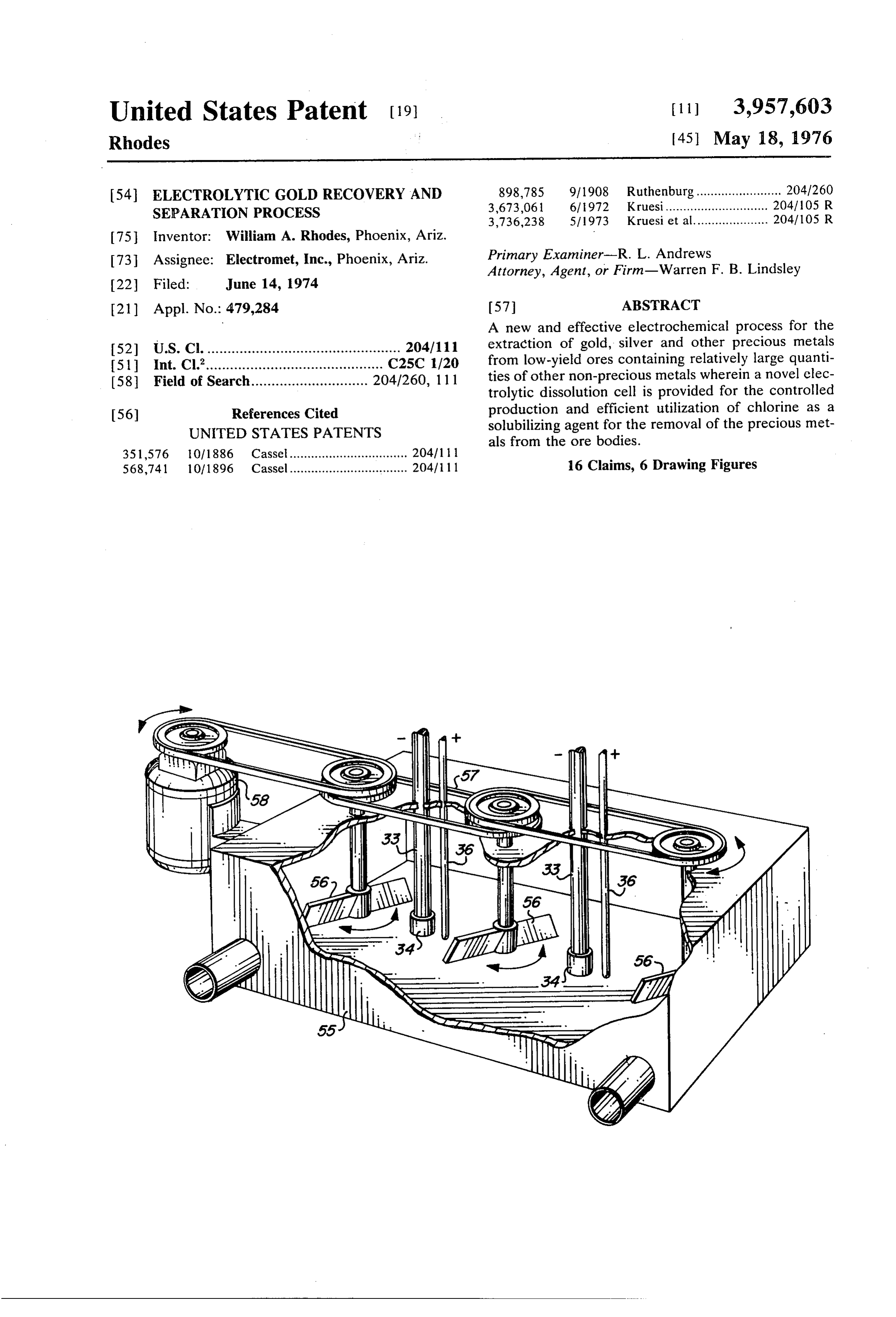
connected to cathode electrode 35, and a motor 41 of the electric field, negatively charged chlorine ion is coupled to tank 31 at its bottom surface so as to rotate drawn towards the anode electrodes 36, 36 whereas tank 31 about its axis either tilted approximately 45° sodium ion is drawn towards the cathode. The chlorine relative to a vertical axis or not as desired. is immediately utilized to solubilize gold, silver and It should be recognized at this point that the dissolu other metals which might be present in the ore in the tion cells 15 may comprise any suitable configuration vicinity of the electrodes 36, 36' forming these metals such as a stationary tank. 55, shown in FIG. 4, with one in colloidal form and remaining in the solution. The or more cathode and anode assemblies 33 and 36 ar sodium ion on the other hand generated within the ranged in the tank. A plurality of agitators 56 are chamber 33, 33' captures hydroxyl molecule (OH) shown driven through a common drive means 57 by a 10 from water forming sodium hydroxide. This sodium motor 58. hydroxide is a valuable by-product and is used in a later FIGS. 5 and 6 illustrate side and top views of a fur stage of the recover process shown in dash lines in FIG. ther modification of the dissolution cells shown in 1.
FIGS. 1-4 wherein a plurality of anodes 36' are shown In earlier experiments utilizing chlorine as a solubiliz as extending into a tank 61 from one side thereof and a 15 ing agent for precious metals the gas has ben injected cathode electrode 35' extending longitudinally of tank into the slurry from a tank. The solubilizing process in 61 along the outside of the other side thereof, as shown. this case was very slow and a large portion of the gas It should be noted that a plurality of caps 34' extend was lost to the atmosphere while only a small part of it outwardly of chamber 33' housing cathode 35' into and was applied to its intended purpose. This very ineffi through the side wall of tank 61 on the opposite side of cient use of the chlorine resulted from its poor distribu anodes 36', one opposite each of the anodes, as shown. tion within the ore slurry and from the lack of an effec Thus, one cathode electrode is used for a plurality of tive control over its injection rate. anodes. The dissolution cell 15 overcomes this problem by A plurality of agitators 56 positioned along the tank virtue of its novel means for chlorine injection by gen 61, are driven by a common motor 58 as shown in FIG. 25 erating chlorine ions (Cl") in its most active state. By 4. electrolysis, the active or nascent chlorine is drawn In the construction of dissolution cells 15, chemically along the entire submerged length of the anode elec inert materials must be employed in the fabrication of trode. In addition, as tank 31 is rotated slowly by motor their tanks such as tanks 31, 55 and 61, chambers 33, 41 or the agitators of tanks 55 and 61 are slowly ro 33', caps 34, 34' and electrodes 35, 35' and 36, 36'. In 30 tated, a constantly fresh supply of slurry is moved past some cases inert liners or surface coatings may be em stationary electrodes 36, 36' so that a high degree of ployed as, for example, rubbr or glass liners inside the exposure to the generated chlorine is provided for the tanks. Cathode electrode 35, 35' are preferably of total amount of slurry under treatment. Furthermore, nickel or stainless steel. Anode electrodes 36, 36' are a the excessive generation of chlorine as evidenced by graphite or carbon rod. Cathode chamber 33, 33' must 35 bubbling off at the surface may be readily prevented by be made from a material which is both chemically inert control of direct current source 38. This control may and electrically insulating. Pyrex has been found to be be accomplished manually or automatically using sen suitable for this purpose. Caps 34, 34' are of a porous sors and feedback control of source 38. In yet another material of very fine pore size so that while it is capable enhancement of the dissolution cells' performance it of absorbing the electrolyte solution and therefore 40 was found that the addition of 100 to 500 parts per capable of passing an electric current it prevents the million of bromine in the form of potassium or sodium free mixing of chemicals from inside cathode chambers bromide, the concentration of chlorine as coupled with 33, 33' with those outside these chambers. Glass frit bromine increased many times over the original. has been used with great success for the fabrication of For most efficient and economical operation the caps 34, 34' while polyethylene screens covered with 45 sodium chloride concentration should be between 50-100 grit sand have also proven satisfactory. When three and six percent. Below three percent an excessive the glass frit is employed it is fused to the end of pyrex amount of oxygen is generated wasting electrical en chamber 33, 33'. ergy; above six percent no oxygen is evident and the The electrolyte 37 contained within chambers 33, curve of chlorine generated vs. electrical energy re 33' is an initially saturated solution of sodium chloride 50 mains substantially flat up to a concentration of ten having a ratio of 35 grams of sodium chloride to 100 percent. Beyond that point sodium chloride tends to be cubic centimeters of water. Electrolyte 32 contained wasted in the slurry. Ordinary sea water aftr adjusting within chambers 31, 31' is water containing between 3 the strength appropriately can also be used. and 6 percent sodium chloride depending on the ore 55 As the dissolution process continues and as more and richness. more of the precious metals pass into solution it will be In the operation of dissolution cells 15 the ore slurry noted that lower and lower levels of electrical current from distribution box 14 is injected into electrolyte 32, must be held to prevent excessive surface gassing of and while motor 41 rotates tank 31 or motors 58 and chlorine. The end point of the process is thus evidenced 61 agitate the solution in tanks 55 and 61 at two to six by a very low level of permissible current. When this revolutions per minute, for example, a controlled elec 60 point is reached the pregnant liquor, i.e., the electro trical current is passed from positive terminal 39 of lyte with its dissolved precious metals is immediately direct-current source 38 to anode electrode 36, into separated from the balance of the ore slurry. If the electrolyte 32 through porous caps 34, 34' and electro separation is postponed more than a few hours a slight lyte 37 to cathode electrodes 35, 35' and to negative drop in precious metal yield can be expected as the terminal 40 of source 38 depending on what type of cell 65 reagents give up the metals again to the ore body. is used. Separation of the dissolved metals begins as the preg Sodium Chloride (NaCL) in water dissociates into nant liquor and slurry is transferred from the tanks of sodium ion (Na") and chlorine ion (Cl). By the action the cells 15 into the rubber-lined thickeners 16. The
Page 7
S 6 thickeners 16 are standard equipment commonly em mineral acids and must have a pore size from 2 to 50 ployed in milling operations for the separation of liq microns.
uids from solids. As diagrammatically illustrated in The output of filter 19 is transferred to separation FIG. 1, a series of thickener tanks 16 are provided. At tank 20 in the form of a black cake. In separation tank the bottom of each tank there is a solids exhaust port 20 the silver and gold metals are separated one from 44 while near the surface of each tank there is a liquids the other in the following manner: exhaust port 45. The solids from a given tank 16 which The cake is first washed with distilled water to the have settled toward the bottom are removed through point where a silver nitrate test shows the wash water to port 44 and are pumped into the next tank to the right be free of sodium chloride.
while the liquids on the surface of a given tank 16 are 10 Concentrated nitric acid is then applied in sufficient removed through port 45 and are pumped into the next quantity to produce saturation. An immediate reaction tank to the left. The solids are thus moved progressively occurs in which silver and other trace metals are dis in one direction while the liquids are moved in the solved. The silver and other metals are then washed opposite direction. Additional water or other washing 15 away and the remaining black colloidal gold is ready solution 46 is injected into the thickener tank to insure for melting in furnace 22A from which it is poured and thorough removal of the dissolved metals from the ore cooled into gold ingots 24. In the melting process it is body prior to final removal of the depleted ore at part necessary to increase the heat very slowly to a dull red 44A. or black red, so that the yellow stage is reached without The pregnant liquor removed at port 45A will appear loss of colloidal particles to the atmosphere. The grad yellow in correspondence with the amount of gold 20 ual heating also vaporizes all traces of sulfur and the present. If the liquor is clear a very low gold content is sides of the crucible must be heated simultaneously to indicated. prevent recondensation of the sulfur thereon and sub From exhaust port 45A the pregnant liquor is trans sequent contamination of the melt.
ferred to the series of precipitating settling tanks 17. In 25 Meanwhile the dissolved silver is transferred into tanks 17 the dissolved gold and silver chlorides are settling tank 21 where the silver is again returned to a forced into a fine metallic precipitate by the addition of state of colloidal suspension for separation, washing sodium dithionite or hydrosulfite (NaSO) which is a and transfer to melting furnace 22B, finally to be dis powerful dechlorinator. As the sodium dithionite pow charged and poured into silver ingots 23. der is added in small amounts the pH of the solution 30 The dimensions and the number of dissolution cells moves toward the acid side and continues to do so as 15 employed in a typical milling operation are, of long as halogens are being cleaned from the metals or course, dependent upon the size of the operation, the from the metal-free liquor. As soon as most of the grade of the ore and other economic considerations. halogens have been removed the gold and silver metals The dimensions and the number of the electrodes 35 appear as a black or blue-black cloud and the pH 35 and 36 must be adequate to handle the required level of change tapers off sharply and comes to rest, no further electrical energy such that a maximum level of 1 to 3 pH change occuring as additional amounts of dithionite watts per 6 square inches of electrode area is not ex are added. A further evidence of the completion of this ceeded. Higher levels can be tolerated for assay pur process is the odor of the dithionite. If still more dithio poses but not in large scale milling operations because nite is added a white cloud of sulfur may suddenly be of the resulting heating and bombardment of colloidal produced. This occurrence does not result in a loss of 40 particles off the electrodes as evidenced by the appear metal but adds the requirement for a special clean up ance of an oily film on the surface of the leach liquor. operation. Experimental studies have indicated that for For very large versions of the dissolution cells 15 it most effective colloidal triggering in this part of the will be found advantageous to add one or more agitator process the liquor should be held at a pH between 5 vanes 50 around the sides of tank 31 to insure thorough and 9 and preferably between 7 and 8. Adjustment of 45 mixing of the slurry and electrolyte. the pH is accomplished by addition of the hydroxide A complete electrochemical process for the effec solution generated within cathode chamber 33, 33' of tive, efficient and economical removal and separation dissolution cells 15 or normal sodium hydroxide solu of gold, silver and other precious metals from relatively tOn. low-yielding ores has thus been provided, the process Once the cloud of colloidal gold and silver appears in 50 utilizing a novel dissolution cell which enables the effi tanks 17 automatic flocculation occurs and, upon very cient generation and utilization of chlorine as a solubi slow stirring or quiet settling the particles settle to the lizing agent.
bottom leaving the clear liquor at the top. At this point In addition to the novelty of the dissolution cells, the it is expedient to move the pH liquor toward a value of 55 importance of using the disclosed pH factors for floccu 4 or 5, preferably with small amounts of hydrochloric lating, separating and automatically controlling the acid. This procedure eliminates the attachment of hy separation and extraction of metals out of solution droxyl groups to metal particles which are impossible should be noted.
to filter. To remove all the unwanted metals such as iron, The output of the settling tanks 17 is removed at port 60 copper, etc. that may have gone into solution along 47 and discharged into a single-stage thickener tank 18. with gold and silver, the circuit of FIG. 1 may be modi A portion of the liquids from thickener tank 18 is re fied as shown in dash lines so that sodium hydroxide turned via line 48 for recycling through settling tanks from cathode container 31 is added to the pregnant 17 to insure a thorough treatment of the complete liquor while the pregnant liquor is mixed uniformly removal of precious metals from the solution. until it has reached a pH rating of 8–9. At this point all The solids from tank 18, i.e. the colloidal precious 65 hydroxides of metals other than gold and silver will metals and residual liquids are removed from tank 18 form clusters of flakes and fall to the bottom of tank via exhaust port 49 and are passed into pressure filter 16A shown in FIG. 1. The pregnant liquor along with 19. The filter employed here must be impervious to the unwanted hydroxides of metals and other impuri
Page 8
ties is pumped into pressure filter 16B where the hy flocculating said colloidal particles by reducing the droxides of unwanted metals and other impurities are pH rating of said pregnant liquor. filtered out leaving the pregnant solution containing 4. The electrochemical process set forth in claim 3 only gold and silver in solution. wherein:
From exhaust port 45B of pressure filter 16B the said flocculation occurs by introducing into said pregnant liquor containing only gold and silver at this pregnant liquor sodium hydroxide and by control point is transferred to the series of precipitating and ling the pH rating of said pregnant liquor. settling tanks 17. In precipitating and settling tanks 17 5. The electrochemical process set forth in claim 4 in the gold and silver are forced into a metallic colloidal 10 further combination with the process step of state. This is accomplished alternately as follows: rendering said pregnant liquor again more acid to l, Bring pregnant liquor to pH rating of 6-7 using destroy the OH bands of the flocculated colloidal hydrochloric or nitric acid. particles.
2. Let pregnant liquor set at this stage a few minutes. 6. The electrochemical process set forth in claim 4 in 3. Add a small amount of sodium hydrosulfite. further combination with the process steps of: 4. Bring pregnant liquor back to pH rating of 6-7 separating said pregnent liquor from the flocculated using hydrochloric or nitric acid. colloidal particles, and 5. At this point gold and silver will come out of solu washing said colloidal particles with nitric acid to tion in the form of blue-black flakes (gold and silver solubilize and remove other mineral elements sulfites) which at first form a black cloud then they 20 therefrom.
begin to grow in size and gradually settle to the bottom 7. The electrochemical process set forth in claim 3 of the tank due to gravity. wherein:
While steps 1 through 5 above are being accom said flocculation occurs by introducing into said plished the pregnant liquor is stirred to speed up the pregnant liquor sodium hydroxide generated at mixing and enhance the uniformity of the mixture. 25 said cathode.
When the gold and silver begin to flocculate (step 5) 8. The electrochemical process set forth in claim 1 in the stirring rate is reduced gradually and then stopped further combination with the process step of: completely to allow the gold and silver sulfite flakes to agitating said slurry during the isolation process. grow in size and settle to the bottom of the tank. 9. The electrochemical process set forth in claim 8 Although but a single embodiment of the present 30 wherein:
invention has been illustrated and described, it will be said second electrolyte comprises a solution of so apparent to those skilled in the art that various changes dium chloride more concentrated than the slurry and modifications may be made therein without depart forming said first electrolyte. ing from the spirit of the invention or from the scope of 10. The electrochemical process set forth in claim 1 the appended claims. 35 wherein:
What is claimed is:
1. An electrochemical process for the extraction of said second container is placed in said first container gold from low-yield ores comprising: and arranged to extend below the slurry in said first container.
mixing milled gold bearing ore with water and so dium chloride in a first container to form a slurry, 40 11. An electrochemical process for the extraction of placing a positively charged anode in said first con gold and silver from low yield ores comprising: tainer to extend below the surface of said slurry, mixing milled gold and silver bearing ore with water, said slurry forming a first electrolyte, potassium sodium bromide and sodium chloride in placing a negatively charged cathode in a second a first container to form a slurry, container containing a second electrolyte, said 45. placing a positively charged anode in said first con second container formed at least in part by a po tainer to extend below the surface of said slurry, rous fluid isolating material, said slurry forming a first electrolyte, connecting said second container to said first con placing a negatively charged cathode in a second tainer below the surface of the slurry in said first container containing a second electrolyte compris container so that upon the passage of electric cur SO ing a solution of sodium chloride, said second con rent between said anode and cathode through said tainer formed at least in part by a porous fluid porous fluid isolating material chlorine generated isolation material.
at the anode and sodium hydroxide generated at connecting said second container to said first con the cathode are kept separated in said first and tainer below the surface of the slurry in said first second containers, container so that upon the passage of electric cur thereby allowing nascent chlorine generated at said rent between said anode and cathode through said anode to disperse in said slurry to solubilize gold porous fluid isolation material chlorine generated particles in said slurry into gold chloride thereafter at the anode and sodium hydroxide generated at to be separated from said slurry as a pregnant li the cathode are kept separated in said first and quor, and 60 second containers, dechlorinating said pregnant liquor to release gold in thereby allowing nascent chlorine generated at said the form of colloidal particles. anode to disperse in said slurry to solubilize gold 2. The electrochemical process set forth in claim 1 particles in said slurry into gold chloride thereafter wherein: to be separated from said slurry as a pregnant li sodium dithionite is used to dechlorinate said preg 65 quor, nant liquor. dechlorinating said pregnant liquor with sodium di 3. The electrochemical process set forth in claim 2 in thinonite to release gold from said slurry in the further combination with the process step of: form of colloidal particles,
Page 9
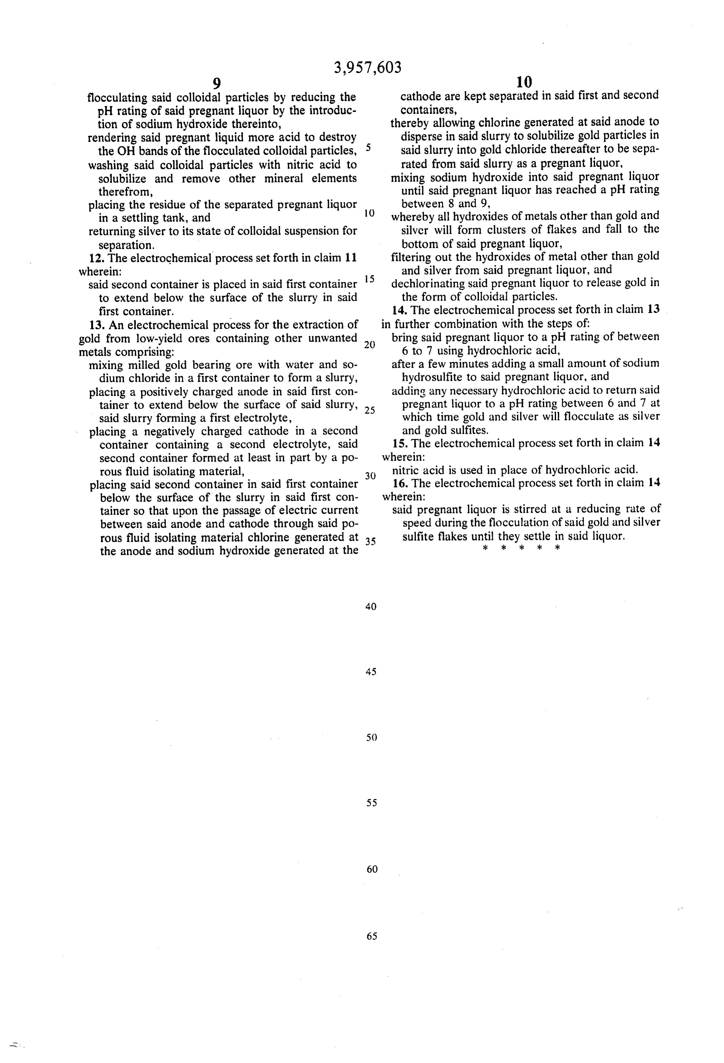
flocculating said colloidal particles by reducing the cathode are kept separated in said first and second pH rating of said pregnant liquor by the introduc containers, tion of sodium hydroxide thereinto, thereby allowing chlorine generated at said anode to rendering said pregnant liquid more acid to destroy disperse in said slurry to solubilize gold particles in the OH bands of the flocculated colloidal particles, said slurry into gold chloride thereafter to be sepa washing said colloidal particles with nitric acid to rated from said slurry as a pregnant liquor, solubilize and remove other mineral elements mixing sodium hydroxide into said pregnant liquor therefrom, until said pregnant liquor has reached a pH rating placing the residue of the separated pregnant liquor 10 between 8 and 9, in a settling tank, and whereby all hydroxides of metals other than gold and returning silver to its state of colloidal suspension for silver will form clusters of flakes and fall to the separation. bottom of said pregnant liquor, 12. The electrochemical process set forth in claim 11 filtering out the hydroxides of metal other than gold wherein: and silver from said pregnant liquor, and said second container is placed in said first container 15 dechlorinating said pregnant liquor to release gold in to extend below the surface of the slurry in said the form of colloidal particles. first container. 14. The electrochemical process set forth in claim 13 13. An electrochemical process for the extraction of in further combination with the steps of gold from low-yield ores containing other unwanted 20 bring said pregnant liquor to a pH rating of between metals comprising: 6 to 7 using hydrochloric acid, mixing milled gold bearing ore with water and so after a few minutes adding a small amount of sodium dium chloride in a first container to form a slurry, hydrosulfite to said pregnant liquor, and placing a positively charged anode in said first con adding any necessary hydrochloric acid to return said tainer to extend below the surface of said slurry, 25 pregnant liquor to a pH rating between 6 and 7 at said slurry forming a first electrolyte, which time gold and silver will flocculate as silver placing a negatively charged cathode in a second and gold sulfites.
container containing a second electrolyte, said 15. The electrochemical process set forth in claim 14 second container formed at least in part by a po wherein:
rous fluid isolating material, 30 nitric acid is used in place of hydrochloric acid. placing said second container in said first container 16. The electrochemical process set forth in claim 14 below the surface of the slurry in said first con wherein:
tainer so that upon the passage of electric current said pregnant liquor is stirred at a reducing rate of between said anode and cathode through said po speed during the flocculation of said gold and silver rous fluid isolating material chlorine generated at sulfite flakes until
they
settle
ink. said liquor.
the anode and sodium hydroxide generated at the
Page 10
UNITED STATES PATENT OFFICE
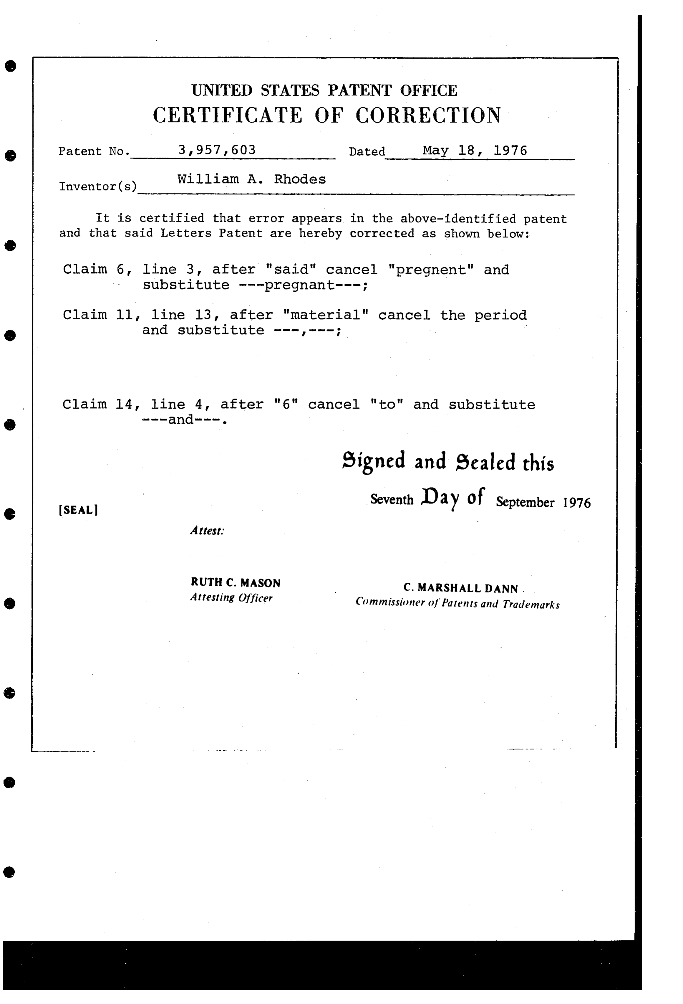
CERTIFICATE OF CORRECTION
() Patent No. 3,957, 603 Dated May 18, 1976 William A. Rhodes
It is certified that error appears in the above-identified patent and that said Letters Patent are hereby corrected as shown below:
Claim 6, line 3, after "said" cancel "pregnent" and substitute ---pregnant---;
Claim ll line 13, after "material" cancel the period
Claim 14 line 4, after "6" cancel "to" and substitute
Signed and Sealed this
Seventh Day of September 1976
O Attesting Officer Commissioner of Patents and Trademarks
Provenance
- Collection
- Cited prior art
- Original PDF
- patentimages.storage.googleapis.com →
- Filed
- 1974-06-14
- Pages
- 10
- Method
- pdftotext (the PDF's own text layer) + pdftoppm 300dpi page scans
- Source
- Google Patents bibliographic record
- Granted
- 1976-05-18
- Inventors
- William A. Rhodes; Electromet Inc
- Transcribed from
- patentimages.storage.googleapis.com →