patent · US4379043
Water-decomposition and gas-generating apparatus
5 April 1983
Page 1 — bibliographic record
United States Patent (19) 11) 4,379,043 Chappelle 45) Apr. 5, 1983 54 WATER-DECOMPOSITION AND 3,793,173 2/1974 Kawahata ....................... 204/272 X GAS-GENERATING APPARATUS 3,957,618 5/1976 Spirig .................................. 204/270 3,990,962 11/1976 Götz ..... ... 204/272 X 75 Inventor: Claude L. Chappelle, Seabrook, Tex. 4,039,422 8/1977 Packer ................................. 204/272 4,040,938 8/1977 Robertson ... ... 204/272 X (73) Assignees: Robert G. Francisco, Flint, Mich.; 4,113,601 9/1978 Spirig .............................. 204/272 X Loren V. Williams, Houston, Tex.;
Dan Hennigan, Houston, Tex.; James FOREIGN PATENT DOCUMENTS
R. Cornish, Houston, Tex.; Charles 2810528 9/1978 Fed. Rep. of Germany . R. Allen, Houston, Tex.
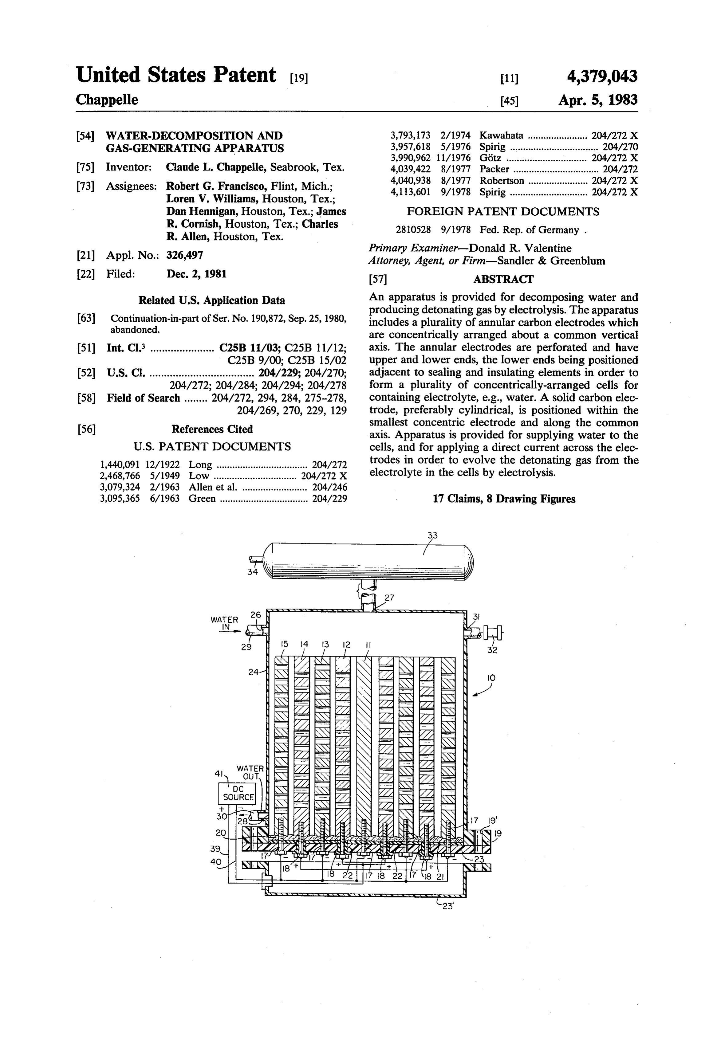
21) Appl. No.: 326,497 Primary Examiner-Donald R. Valentine Attorney, Agent, or Firm-Sandler & Greenblum 22 Filed: Dec. 2, 1981 57 ABSTRACT Related U.S. Application Data An apparatus is provided for decomposing water and producing detonating gas by electrolysis. The apparatus (63) Continuation-in-part of Ser. No. 190,872, Sep. 25, 1980, includes a plurality of annular carbon electrodes which abandoned.
are concentrically arranged about a common vertical 51) Int. Cl. ...................... C25B 11/03; C25B 11/12; axis. The annular electrodes are perforated and have C25B 9/00; C25B 15/02 upper and lower ends, the lower ends being positioned 52) U.S. C. .................................... 204/229; 204/270; adjacent to sealing and insulating elements in order to 204/272; 204/284; 204/294; 204/278 form a plurality of concentrically-arranged cells for 58) Field of Search ........ 204/272, 294, 284, 275-278, containing electrolyte, e.g., water. A solid carbon elec 204/269, 270, 229, 129 trode, preferably cylindrical, is positioned within the 56 References Cited smallest concentric electrode and along the common axis. Apparatus is provided for supplying water to the
1,440,091 12/1922 Long ................................... 204/272 trodes in order to evolve the detonating gas from the 2,468,766 5/1949 Low ................................ 204/272 X electrolyte in the cells by electrolysis. 3,079,324 2/1963 Allen et al. ......................... 204/246 3,095,365 6/1963 Green .................................. 204/229 17 Claims, 8 Drawing Figures
Page 2
Drawing sheet — no readable text.
Page 3
Drawing sheet — no readable text.
Page 4
Drawing sheet — no readable text.
Page 5
apart, and perforated concentric electrodes which are
WATER-DECOMPOSITION AND positioned about a central, solid carbon electrode.
GAS-GENERATING APPARATUS
SUMMARY OF THE INVENTION
CONTINUING APPLICATION Accordingly, it is a general object of the present This application is a Continuation-in-Part of U.S. invention to provide a new and improved water-decom patent application Ser. No. 190,872, filed Sept. 25, 1980, position and gas-generating apparatus which is more now abandoned. The contents of such application are efficient, and which can utilize lower voltage and am expressely incorporated by reference herein. perage to produce a predetermined volume of detonat 10 ing gas than known gas-generating apparata.
BACKGROUND OF THE INVENTION It is an additional object of the present invention to 1. Field of the Invention The present invention gener provide a new and improved water-decomposition and ally relates to a water-decomposition and gas-generat gas-generating apparatus which can generate detonat ing apparatus, and more particularly to a water-decom ing gas at a quicker rate than prior gas-generating appa position and gas-generating apparatus used to produce 15 ratus, and which can simply and rapidly produce such detonating gas or oxy-hydrogen gas in an efficient man detonating gas.
ner by the electrolysis of water. Yet another object of the present invention is to pro 2. Discussion of Prior Art vide a new and improved water-decomposition and Prior art apparatus for producing detonating gas via gas-generating apparatus which has enhanced conduc the electrolysis of water are unsatisfactory for several tivity due to the carbon material which comprises the reasons. They require too much electric current and electrodes, and which speeds the reaction as a result. amperage to produce a satisfactory amount of detonat Still another object of the present invention is to ing gas in relation to the energy input required, and are provide a new and improved water-decomposition and thus inefficient for desired purposes, e.g., for use in gas-generating apparatus which produces detonating running automobile engines or stationary power en 25 gines, such as energy plants for heating buildings, as gas more efficiently than previous devices as a result of well as for cooking. The following patents, cited during achieved byelectrode increased providing surface area; this increase is the electrodes with perforations.
the prosecution of the above-referenced parent applica Still another object of the present invention is to tion, are examples of such unsatisfactory water-decom provide a new and improved water-decomposition and position apparata. 30 gas-generating apparatus which is capable of detecting
Spirig, U.S. Pat. No. 4,113,601, discloses a water decomposition apparatus for producing detonating gas the level of water within the apparatus, and which is or oxy-hydrogen gas; this decomposition apparatus capable of regulating the level of water in the apparatus includes a plurality of electrolytic cells formed between in Yet response to the level detected. a nested plurality of endless laminar electrodes. Electro providea afurther 35 object of the present invention is to new and improved water-decomposition and lyte circulates through the assembly, and current is applied to the inner and outer electrodes from a DC gas-generating apparatus which can be immersed in an electrolyte, e.g., water, or which can be provided with source. When the electrode assembly is to be immersed an enclosed water circulatory system for delivering in electrolyte, the outermost electrode is placed within liquid electrolyte.
an electrically inoperative shielding member. 40
Spirig, U.S. Pat. No. 3,957,618, discloses a water Briefly, the above and other objects, features, and decomposition apparatus for producing detonating gas advantages of the present invention are attained in one or oxy-hydrogen gas; the apparatus includes a plurality aspect thereof by providing an apparatus for decompos of adjacent electrolysis cells. The cells are positioned ing water and producing detonating gas which includes within a common compartment, and are constructed as 45 a plurality of annular carbon electrodes, concentrically open vessels, each cell opening into the most closely arranged about a common vertical axis, each of the adjacent, lower-positioned cell. A gas outlet or dis annular electrodes having an upper end and a lower charge is provided for outwardly conducting gas which end. Each annular electrode also has a plurality of per is produced by the apparatus. forations located along its surface. A central, solid car Long, U.S. Pat. No. 1,440,091, discloses an electrode 50 bon electrode is positioned coextensively along the apparatus comprising a plurality of concentric elec common vertical axis. Sealing and insulating elements trodes formed of glass tubes filled with mercury, or are positioned adjacent to the lower electrode ends to from metal rods, e.g., copper covered with a thin plati form, with the annular electrodes and central electrode, num sleeve. a plurality of concentrically-arranged cells. Means for Gotz, U.S. Pat. No. 3,990,962, discloses an electro 55 supplying liquid electrolyte to the cells, and means for lytic cell device comprising a plurality of generally applying a DC current across the electrodes are also concentric tubular electrodes positioned within a gener provided in order to evolve detonating gas from the ally cylindrical pressure vessel. Together, the elec cells.
trodes and vessel form a plurality of serially-connected cells which are spaced from each other. By applying a 60 BRIEF DESCRIPTION OF THE DRAWINGS DC voltage source across the electrodes, hydrogen and The above and other objects, features, and advan oxygen gas will be produced, and will be collected as a tages of the present invention will become more fully mixture in a collecting chamber located between the apparent to those of ordinary skill in the art to which upper surface of the liquid electrolyte and the lid of the this invention pertains from the following detailed de pressure vessel. 65 scription, when considered in connection with the ac None of the above patents, however, discloses a com companying drawings, in which like reference charac bination water-decomposition and gas-generating appa ters designate like or corresponding parts throughout ratus which has a plurality of carbon, annular, spaced the several views, and wherein:
Page 6
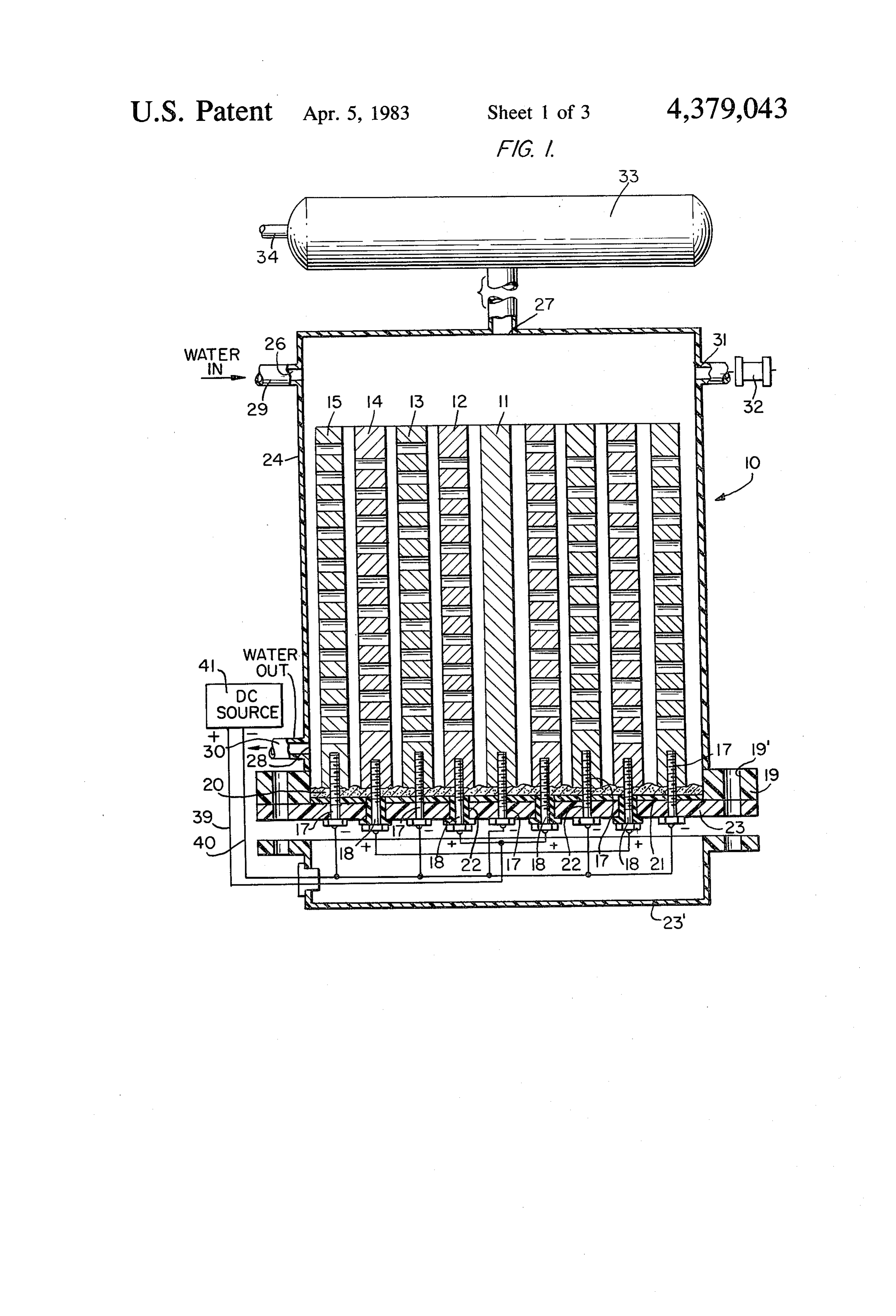
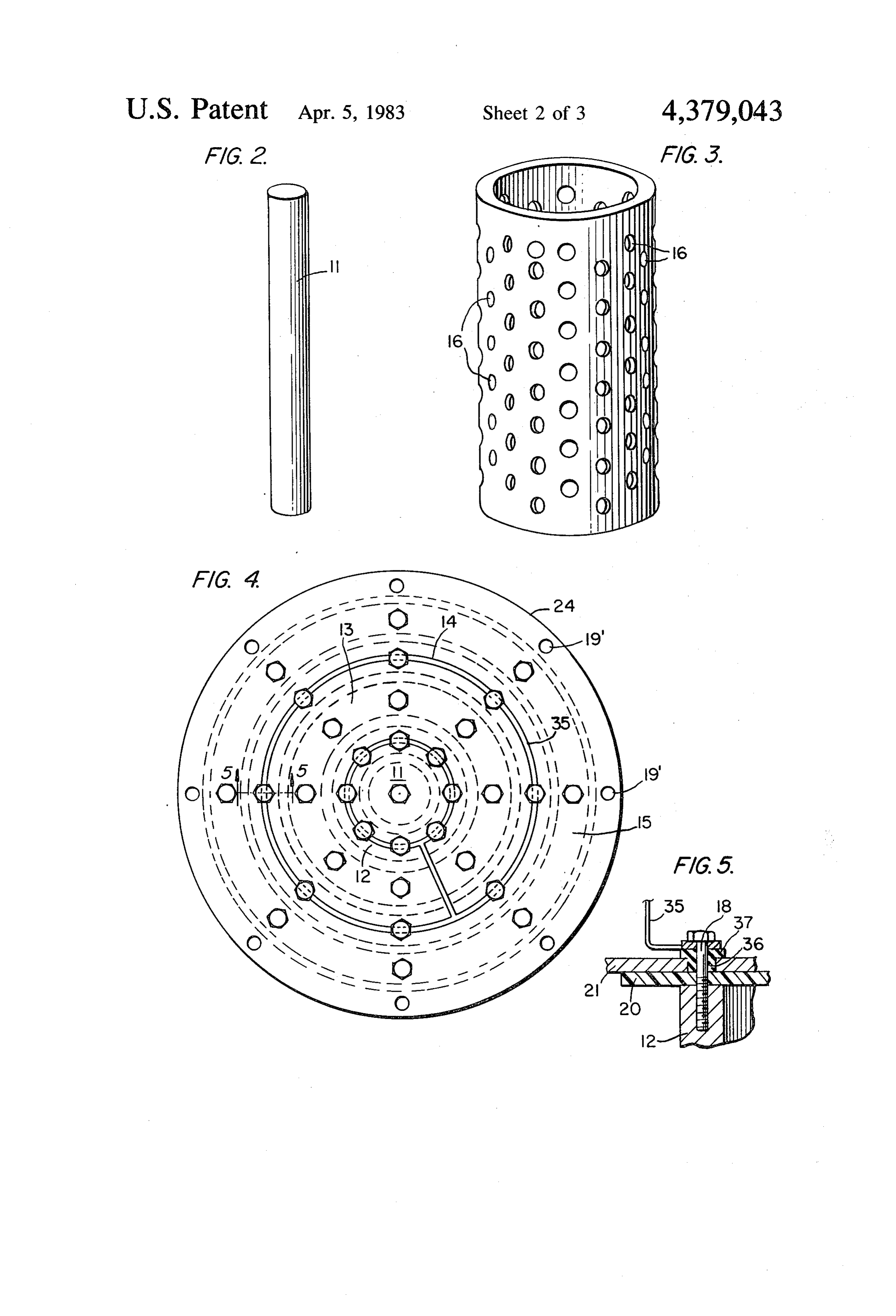
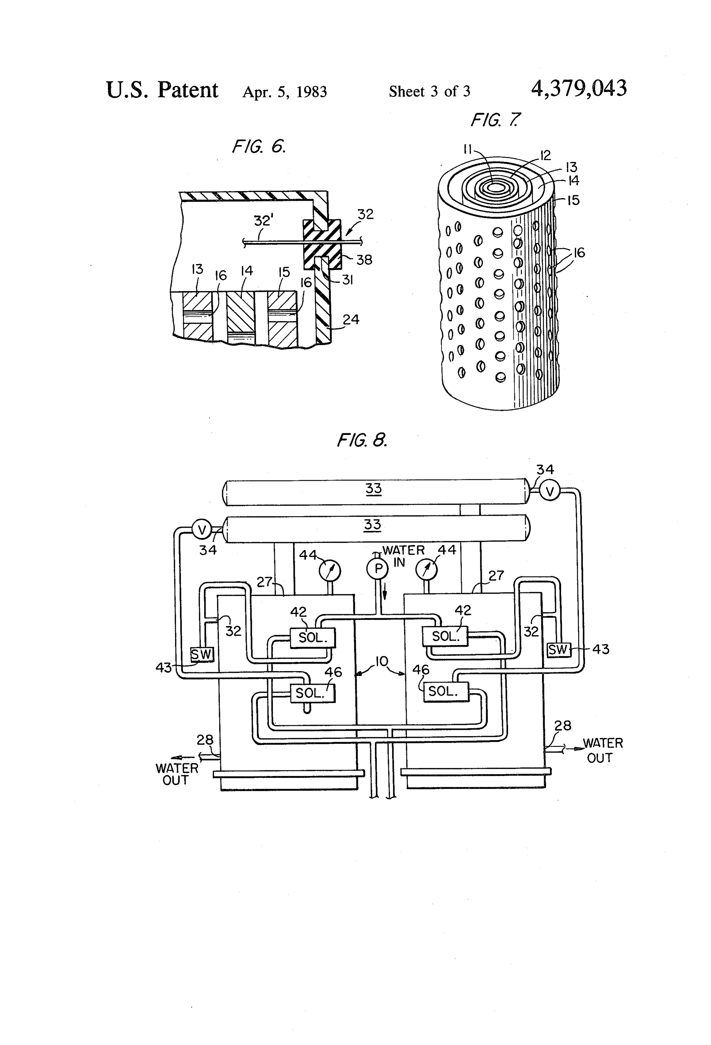
FIG. 1 is a sectional view of a water-decomposition apertures 26 and 28, respectively, can be attached to and gas-generating apparatus formed in accordance inlet and outlet conduits 29 and 30, respectively. with the present invention; The container is also advantageously provided with a FIG. 2 is a perspective view of the solid central elec water-level control aperture 31, through which a water trode forming a portion of the apparatus of FIG. 1; 5 level probe or detector 32 is attached for sensing the FIG. 3 is a perspective view of one of the annular, level of water within container or shell 24 and for con perforated concentric electrodes forming a portion of trolling the operation of water supply means, e.g., a the apparatus of FIG. 1; pump, to the container.
FIG. 4 is a bottom plan view of the apparatus of FIG. 10 A condensation tank 33 can be provided for collect 1; ing detonating gas escaping the apparatus via gas outlet FIG. 5 is a sectional view of one positive electrode aperture 27, and tank 33 can itself be provided with a assembly of the apparatus of FIG. 1; second, detonating-gas outlet aperture 34 for allowing FIG. 6 is a sectional view of a water-level sensor detonating gas to escape the gas-generating apparatus forming a portion of the apparatus of FIG. 1; and enter a larger system at a desired location. Any FIG. 7 is a perspective view of the assembled concen 5 suitable conduit can be connected to second gas outlet tric electrodes which form a portion of the apparatus of aperture 34.
FIG. 1; and The carbon electrodes of the present invention are FIG. 8 is a schematic view of a system incorporating best illustrated in FIGS. 2 and 3. FIG. 2 shows solid
carbon central electrode 11, shown as having a gener
DETAILED DESCRIPTION OF THE
ally cylindrical shape, and FIG. 3 illustrates one of the
DRAWINGS
annular carbon electrodes 12-15. By providing perfora tions 16 along the surface of each annular carbon elec
Referring more specifically to the drawings, FIG. 1 trode, the surface area of each carbon electrode is in illustrates the overall construction of a water-decompo 25 creased by approximately 25.2% in comparison to the sition and detonating gas-generating apparatus 10. The surface area of a similarly-dimensioned annular elec apparatus includes a central, generally cylindrical solid trode lacking perforations; this increase in surface area carbon electrode 11. Surrounding the solid electrode, in of each electrode adapted to contact liquid electrolyte spaced relation, are a plurality of annular electrodes 12, in the apparatus enhances the production of detonating 13, 14, and 15. A representative annular and hollow 30 gas when equal amounts of electricity and electrolyte, electrode is best illustrated in FIG. 3, and includes a e.g., water, are utilized. As is evident from FIGS. 1, 4, plurality of perforations 16 extending over its entire and 7, the concentric annular electrodes are provided height and along its entire peripheral surface area; this with an increasing diameter, as seen in a direction taken increases the surface area which will contact liquid from the interior of the apparatus towards the exterior; electrolyte in the apparatus, and thus increases the effi 35 in other words, it is readily apparent that each succes ciency of the apparatus in producing detonating gas. sive electrode must have a larger diameter than the The central electrode 11 and annular electrodes 13 and electrode adjacent to it which is located closer to the 15, as shown, are negative electrodes; electrodes 12 and central vertical axis of the apparatus. 14 are shown as being positive. As seen in FIG. 1, each FIG. 4 is a bottom plan view of the apparatus, and electrode has an upper and lower end; the lower ends of 40 better illustrates the electric connection of the elec the electrodes are attached to connector bolts 17, for trodes. A copper connector ring 35 is attached to the the negative electrodes, and brass connector bolt 18, for bottom of electrodes 12 and 14 by a brass washer 36. the positive electrodes. The bottom portions of the This connection is best illustrated in FIG. 5, in which electrodes extend through bottom plate 23 having the copper connector ring is shown attached to the flange 19, epoxy sealing layer 20, and dielectric plate 21. 45 bottom of one anode by brass connector bolt 18, which Flange 19 includes a plurality of apertures 22, through extends through the bottom plate 23, insulating sleeve/- which brass connector bolts 17 and 18 can extend. The feed-through insulator 37, the brass washer, dielectric flange 19 of plate 23 can be connected to a bottom plate plate 21, epoxy layer 20, and into the bottom of the 23', as best seen in FIG. 1. An electrically non-conduc electrode. The insulator and washer serve to com tive shielding member or shell 24 surrounds and en 50 pletely isolate positively-charged brass bolt 18 from closes the entire assembly. dielectric plate 21 and outer container or shell 24. Connecting bolts 17 for the negative electrodes are The bottom portion of each electrode 12-15 is pro circumferentially disposed about the apparatus, as best vided with a plurality, e.g., eight, circumferential holes seen in FIG. 4. Connector bolts 18 are also circumferen which are adapted to receive a plurality of brass con tially attached to electrodes 12 and 14. 55 nector bolts, 17 or 18, respectively. Solid carbon elec Closure plate 23' is attached to shell 24 via flange 19 trode 11 includes only one central bolt hole, as seen in and by bolt holes 19, which are adapted to receive bolts FIG. 5, for attachment to the copper ring. or similar, conventional attaching elements (not shown) Water enters the system via water inlet aperture 26, for securing the assembly. as shown in FIG. 1, and initially displaces air outwardly The top edges of electrodes 12-15 are open and are 60 through detonating-gas aperture 27. When water or unattached, the annular spaces located between each other liquid electrolyte attains a predetermined level pair of adjacent electrodes 11-15 serving as cells, within the apparatus, water-level probe 32, best illus through which water or other liquid electrolyte passes trated in FIG. 6, positioned within water-level control via perforations 16. Water enters the shell and apparatus aperture 31, detects the presence of water, and commu via water inlet aperture 26. The top of the shell or con 65 nicates with a water supply pump (not shown) to cease tainer is provided with a detonating-gas outlet aperture its operation. As shown in FIG. 6, the level detector 27, and the side of the container is provided with a includes a probe 32, and is fit within aperture 31 by a water outlet aperture 28. The inlet and outlet water neoprene bushing and seal 38.
Page 7
As seen in FIG. 1, electrical connections to the elec In this arrangement, the outermost cylinder has a posi trodes are provided by positive and negative leads 39 tive polarity, the next adjacent inner cylinder has a and 40, respectively. The connections enter through negative polarity, the next one positive, and the fourth bottom plate 23 via feed-through insulators 37, and are one negative. The innermost, solid cylinder comprises a taken to a suitable direct-current source 41 having posi one-inch diameter core of positive polarity. This appa tive and negative terminals. The source can take any ratus is provided to extract hydrogen from water at a conventional form, e.g., a battery, generator, or a recti relatively low voltage of 12 volts DC. This voltage is fier energized by an alternating-current source.
In operation, voltage is applied to the assembly by applied sis of to the carbon cylinders, which begin electroly the water to convert it to oxygen and hydrogen direct-current source 41, and current flows between the 10 (detonating) gas. This voltage is applied to the cell at 80 electrodes via the liquid electrolyte in the assembly. amps, and detonating
Electrolysis of the electrolyte, e.g., water, then occurs, be piped to a storagegas is thus released and adapted to and gas is produced along the surface of all of the elec ducted to any unit or system from tank, where it can be con trodes, including the surfaces of all of the perforations A pump can be provided to which can utilize such gas. of each electrode. Detonating gas thus collects above 15 From the foregoing description, oneofskilled dispose waste material.
the electrolyte level within shell 24, and passes out can easily ascertain the essential characteristicsin the of art this wardly from the apparatus through aperture 27. As invention, and, without departing from the spirit and detonating gas is formed, the level of liquid declines, scope and probe 32 indicates to the water supply pump (not tions ofthereof, can make various changes and modifica the invention to adapt it to various usages and shown) to again supply water to the apparatus so that it 20 conditions.
will again attain an optimal level for efficient gas pro What is claimed is:
duction.
Probe 32 carries no voltage, but controls the level of 1. Apparatus for decomposing water and producing water by virtue of impedance via a processor (not detonating gas comprising:
shown) located away from the apparatus. 25 (a) a plurality of annular carbon electrodes concentri Although five electrodes are illustrated, as shown in cally arranged about a common vertical axis, said FIG. 7, when arranged concentrically, it is apparent annular electrodes each having an upper end and a that any number of electrodes could equally well be lower end, each annular electrode having a plural utilized. The current applied to the electrodes via di ity of perforations along its surface; rect-current source 41 needs to be adjusted as the num 30 (b) a central, solid carbon electrode positioned along ber of electrodes increases in order to maintain optimal said axis;
production of detonating gas. As indicated above, water (c) sealing and insulating elements positioned adja or other liquid electrolyte is supplied to the system cent said lower electrode ends to form, with the when necessary in an amount related to the volume of annular electrodes and central electrode, a plural gas generated by the system. 35 ity of concentrically-arranged cells which are The apparatus can be provided with an enclosed adapted to hold liquid electrolyte; water circulatory system, or can be immersed in a larger (d) means for supplying liquid electrolyte to said water vessel in order to provide a suitable supply of cells; and liquid electrolyte. (e) means for applying a direct current across said FIG. 8 is a schematic view of a system utilizing the 40 electrodes in order to evolve detonating gas from present apparatus. As shown, the system includes two said cells.
cells, each of which is provided with a water inlet sole 2. Apparatus in accordance with claim 1 wherein said noid 42 for controlling electrolyte supply; when an annular carbon electrodes comprise perforated concen optimal level of water is reached within the cells, water tric cylinders.
level probes 32 instruct the solenoids to temporarily 45 3. Apparatus in accordance with claim 2 wherein said terminate water flow from respective pumps. When cylinders are placed within an enclosure which com current is supplied to the cells, detonating gas is gener prises a hollow metal shell.
ated by the electrolytic process, and passes outwardly 4. Apparatus in accordance with claim 3 wherein said from each apparatus via detonating-gas outlet aperture hollow shell is concentrically arranged about said elec 27 into a respective condensation/gas-collecting tank 50 trodes, said shell having an upper end and a lower end, 33. As the pressure exerted by the gas increases, the said lower end of said shell being sealed by a dielectric current supplied can be decreased by virtue of electric plate, an epoxy layer, a bottom plate, and a closure pressure switches 43. These switches are controlled in plate.
accordance with the measurements taken by pressure 5. Apparatus in accordance with claim 2 wherein gauges 44 located in the upper portion of each cell. 55 each of said concentrically-arranged cells is bounded by Detonating gas moves from condensation tanks 33 a pair of adjacent electrodes and by said insulating and through tubing, e.g., copper, via and to detonating-gas sealing elements, said insulating and sealing elements outlet solenoids 46; the gas is then preferably conducted comprising a dielectric plate and a layer of epoxy. to low-pressure storage tanks (not shown). 6. Apparatus in accordance with claim 1 further com The water outlet apertures 28 can be provided with a 60 prising a shell for enclosing the electrode apparatus and valve for optional back-washing or emptying of the which is adapted to contain a liquid electrolyte. apparatus. 7. Apparatus in accordance with claim 6 further com As one example of the apparatus, the cell 10 com prising a water inlet opening adapted to conduct a sup prises a plurality of hollow, annular carbon cylinders, ply of water or other liquid electrolyte to said cells. each having one-half-inch-thick walls, each six inches 65 8. Apparatus in accordance with claim 1 wherein said long (high), and each being concentrically separated electrodes are electrically connected in series by a cop from adjacent cylinders by one-eighth of an inch. The per ring, said apparatus being combined with a direct diameter of the outermost carbon cylinder is six inches. current source connected across said electrodes.
Page 8
9. Apparatus in accordance with claim 8 wherein said positioned within a shell surrounding said electrodes, direct-current source comprises a battery. and further comprising means for controlling the opera 10. Apparatus in accordance with claim 8 wherein tion of a water supply pump in accordance with the said direct-current source comprises a generator. level of water detected.
11. Apparatus in accordance with claim 8 wherein 15. Apparatus in accordance with claim 14 wherein said direct-current source comprises a rectifier ener said water-level detector comprises a probe and a neo gized by an alternating-current source. prene seal.
12. Apparatus in accordance with claim 11 further comprising 16. Apparatus in accordance with claim 1 further comprising means for detecting the pressure of gas a conduit attached to a shell surrounding generated by the apparatus, and for reducing the cur 10 said electrodes, said conduit connected to a detonating rent supply to the electrodes in accordance with the gas outlet aperture and adapted to conduct detonating pressure detected. gas from said shell to a condensation tank for storing 13. Apparatus in accordance with claim 1 wherein said detonating gas.
each of said concentrically-arranged electrodes com comprising 17. Apparatus in accordance with claim 1 further prises a hollow tube or cylinder. 15 a shell surrounding said electrodes, said 14. Apparatus in accordance with claim 1 further shell including a water aperture, a water outlet aper comprising a water-level detector for determining the ture, and a detonating-gas sk sk outlet
aperture.
level of water within said apparatus, said detector being
Provenance
- Collection
- Cited prior art
- Original PDF
- patentimages.storage.googleapis.com →
- Filed
- 1981-12-02
- Pages
- 8
- Method
- pdftotext (the PDF's own text layer) + pdftoppm 300dpi page scans
- Source
- Google Patents bibliographic record
- Granted
- 1983-04-05
- Inventors
- Claude L. Chappelle
- Transcribed from
- patentimages.storage.googleapis.com →