patent · US4332219
Electrocombustion engine
1 June 1982
Page 1 — bibliographic record
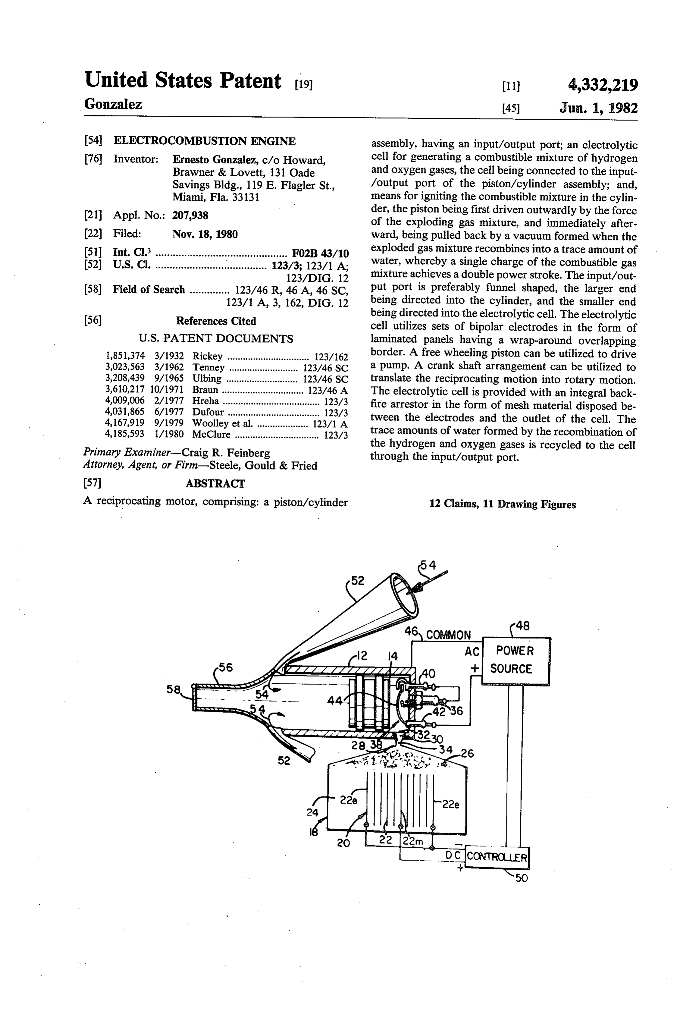
United States Patent (19) 11 4,332,219 Gonzalez 45) Jun. 1, 1982 54 ELECTROCOMBUSTION ENGINE assembly, having an input/output port; an electrolytic 76 Inventor: Ernesto Gonzalez, c/o Howard, cell for generating a combustible mixture of hydrogen Brawner & Lovett, 131 Oade and oxygen gases, the cell being connected to the input Savings Bldg., 119 E. Flagler St., /output port of the piston/cylinder assembly; and, Miami, Fla. 33131 means for igniting the combustible mixture in the cylin 21 Appl. No.: 207,938 der, the piston being first driven outwardly by the force of the exploding gas mixture, and immediately after (22 Filed: Nov. 18, 1980 ward, being pulled back by a vacuum formed when the 51 Int. Cl. .............................................. F02B 43/10 exploded gas mixture recombines into a trace amount of 52 U.S. Cl. ....................................... 123/3; 123/1 A; water, whereby a single charge of the combustible gas 123/DIG. 12 mixture achieves a double power stroke. The input/out 58) Field of Search .............. 123/46 R, 46 A, 46 SC, put port is preferably funnel shaped, the larger end 123/1 A, 3, 162, DIG. 12 being directed into the cylinder, and the smaller end (56) References Cited being directed into the electrolytic cell. The electrolytic cell utilizes sets of bipolar electrodes in the form of
1,851,374 3/1932 Rickey ................................ 123/162 border. A free wheeling piston can be utilized to drive 3,023,563 3/1962 Tenney ... 123/46 SC a pump. A crank shaft arrangement can be utilized to 3,208,439 9/1965 Ulbing ... 123/46 SC translate the reciprocating motion into rotary motion. 3,610,217 10/1971 Braun...... 123/46. A The electrolytic cell is provided with an integral back 4,009,006 2/1977 Hreha..... ... 123/3 fire arrestor in the form of mesh material disposed be 4,031,865 6/1977 Dufour ............ ... 123/3 tween the electrodes and the outlet of the cell. The 4,167,919 9/1979 Woolley et al. 123/1 A 4,185,593 1/1980 McClure ................................. 123/3 trace amounts of water formed by the recombination of Primary Examiner-Craig R. Feinberg the hydrogen and oxygen gases is recycled to the cell through the input/output port.
Attorney, Agent, or Firm-Steele, Gould & Fried
A reciprocating motor, comprising: a piston/cylinder 12 Claims, 11 Drawing Figures
Page 2
Drawing sheet — no readable text.
Page 3
Drawing sheet — no readable text.
Page 4
Drawing sheet — no readable text.
Page 5
Drawing sheet — no readable text.
Page 6
ELECTROCOMBUSTON ENGINE SUMMARY OF THE INVENTION
To provide a system which uses electricity as prime
BACKGROUND OF THE INVENTION energizer to run an internal-combustion engine. It is an 1. Field of the Invention object of this invention to provide a non-polluting en This invention relates to electro-chemical combus gine power system.
tion engines, and in particular, to an engine utilizing the It is yet another object of this invention to provide an recombination of hydrogen and oxygen gases to pro engine power system wherein the combustible mixture vide a double power stroke for a piston/cylinder assem 10 is water, which is substantially recycled. bly, as a means of using electric power as the prime combustibleanother
It is yet object of this invention to utilize a mixture of hydrogen and oxygen gases, an energizer of an internal combustion piston engine. anaero environment, to provide a double power stroke 2. Prior Art in a piston/cylinder assembly.
Many apparatus are known wherein an electrolytic It is yet another object of this invention to utilize the cell is used to generate hydrogen gas, for example, 15 vacuum formed after the recombination of hydrogen which then forms all or part of the fuel mixture used in and oxygen gases to double the power output with an otherwise typical internal combustion engine. In respect to the energy required to obtain hydrogen and each of these instances, the oxygen gas is not used in the oxygen from water.
fuel mixture, and it is generally conceded that the use of It is yet another object of this invention to provide hydrogen and oxygen gases as a fuel is too dangerous. 20 more efficient means for the production of hydrogen In modern times, the use of hydrogen and oxygen gases and oxygen gases.
as a fuel seems limited to the field of welding. Two It is yet another object of this invention to provide an examples of this use are described in U.S. Pat. No. improved bipolar electrode for electrolytic processes. 4,014,777-Brown and No. 3,356,600-Henes. In two en It is still another object of this invention to provide a gine applications, for example, the hydrogen and oxy 25 backfire arrestor so that hydrogen and oxygen gases gen mixture is mixed with air from the atmosphere, as in may be safely used as a sole fuel for electro-combustio U.S. Pat. No. 3,980,053-Horvath and in another is engines and other applications. mixed with the fuel, as in U.S. Pat. No. 4,023,545 These and other objects of this invention are accom Mosher, et al. In each of these instances, the use of plished by, in the most basic form, a reciprocating mo hydrogen and oxygen gas alone is not even suggested, 30 tor, comprising: a piston/cylinder assembly, having an and in many instances, is said to be dangerous or im input/output port; an electrolytic cell for generating a practical. U.S. Pat. Nos. 2,365,330-Carmicahel and combustible mixture of hydrogen and oxygen gases, the 3,311,097-Mittelsteadt disclose the use of hydrogen and cell being connected to the input/output port of the piston/cylinder assembly; and, means for igniting the oxygen as a fuel, however, the mixture is said to be used 35 combustible mixture in the cylinder, the piston being with a typical internal combustion engine. Typical in ternal combustion engines can not operate on the explo first driven outwardly by the force of the exploding gas mixture, and immediately afterward, being pulled back sion-implosion principle utilized in this invention. U.S. by a vacuum formed when the exploded gas mixture Pat. No. 2,496,623-Fragale discloses a two cycle inter recombines nal combustion engine which operates on hydrogen and 40 single chargeinto a trace amount of water, whereby a oxygen gas mixture, but the piston is provided with a double powerofstroke. the combustible gas mixture achieves a number of grooves, in order that water formed during bly funnel shaped, the The input/output port is prefera the combustion process can run out of the cylinder. cylinder, and the smaller endendbeing larger being directed into the
Such a configuration would preclude the use of a vac electrolytic cell. The electrolytic celldirected into the uum to provide the second half of the double power 45 bipolar electrodes in the form of laminated panelssetshav utilizes of stroke. U.S. Pat. No. 1,905,627-Holland purports to ing a wrap-around overlapping border. A free wheeling teach the use of hydrogen and oxygen gas, alone, to piston can be utilized to drive a pump. A crank shaft operate an internal combustion engine. The engine, arrangement can be utilized to translate the reciprocat however, requires two actuated valve assemblies, and ing motion into rotary motion. The electrolytic cell is makes no mention of the formation of a vacuum or a 50 double power stroke. In fact, it is likely that the Holland provided with an integral backfire arrestor in the form of mesh material disposed between the electrodes and apparatus would be rendered inoperable as any vacuum the outlet of the cell. The trace amounts of water formed would cause both valves to open, more than formed by the recombination of the hydrogen and oxy likely preventing the piston from being pulled back by gen gases are recycled to the cell through the input/out the vacuum, obviating the double power stroke of this 55 put port.
invention. Not only does this invention provide more efficient In summary, there is no known device comparable to means for electrolizing hydrogen and oxygen gases, this the electro-combustion engine taught herein, wherein invention doubles the efficiency of any electrolytic cell, hydrogen and oxygen gases, alone, and in a stochiomet by utilizing the vacuum formed as a result of the recom ric combustible proportion, are used as the sole ener 60 bination of hydrogen and oxygen gases to pull a piston gizer for powering a piston in a piston/cylinder assem back onto a cylinder, thereby effectively doubling the bly, wherein no valves are needed between the source power with respect to the energy required to run the of the hydrogen and oxygen gases and the cylinder, and electrolytic cell. Further, problems due to heat and wherein the piston/cylinder assembly is sufficiently friction can also be minimized, as the piston/cylinder sealed that upon ignition of the gas mixture, the piston 65 assembly runs essentially cool. That is, notwithstanding is first driven outwardly, and after recombination of the the very high temperature of the hydrogen-oxygen gases into trace amounts of water, the piston is pulled explosion, there is virtually no heat build up even when back into the cylinder by the resulting vacuum suction. the motor is run continuously. Heat will be mostly fric
Page 7
tion from the working parts of the engine. The speed of in other applications and are not to be barred. A back the motor can be controlled electrically, that is by ad fire arrestor is formed by a metal or plastic mesh mass or justing the voltage applied to the electrodes in the elec otherwise 26, disposed above the electrode plates and trolytic cell and/or by changing the geometry of the below the outlet 28 of the electrolytic cell. Particles of combustion chamber. water clinging the mesh material effectively eliminate the hazards of backfire, and at the same time, permit the
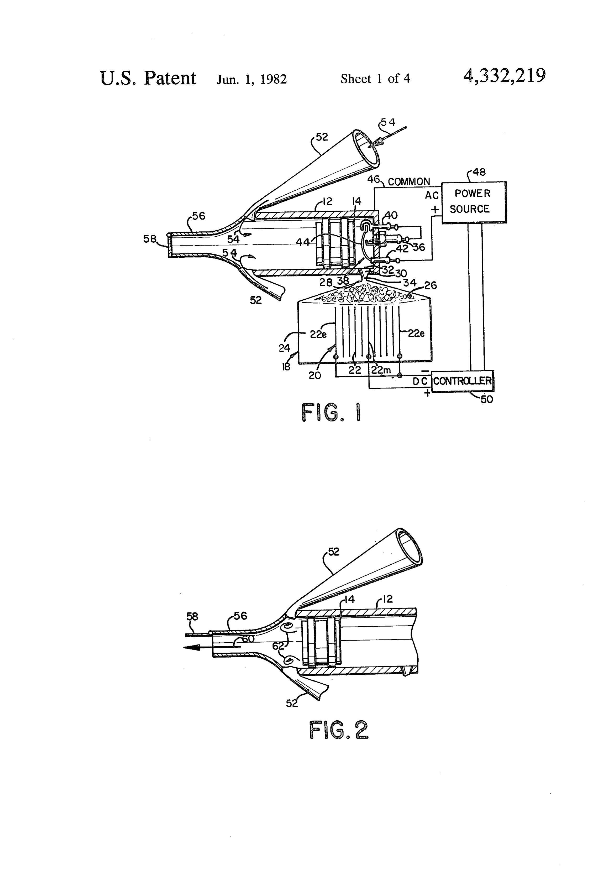
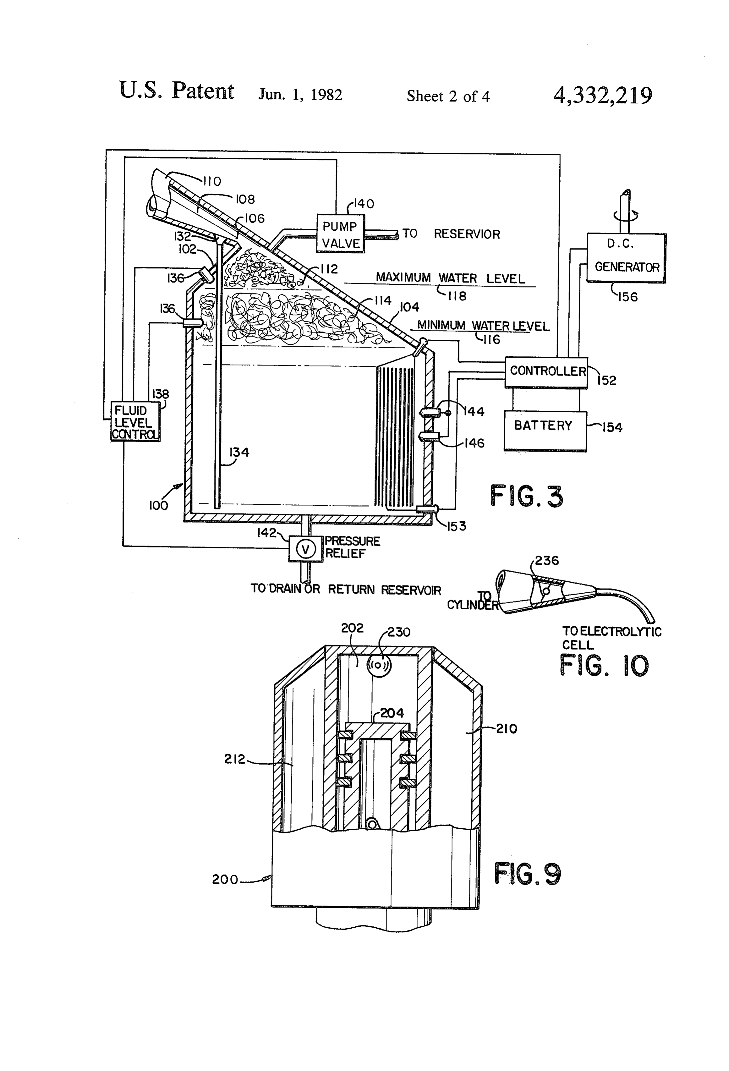
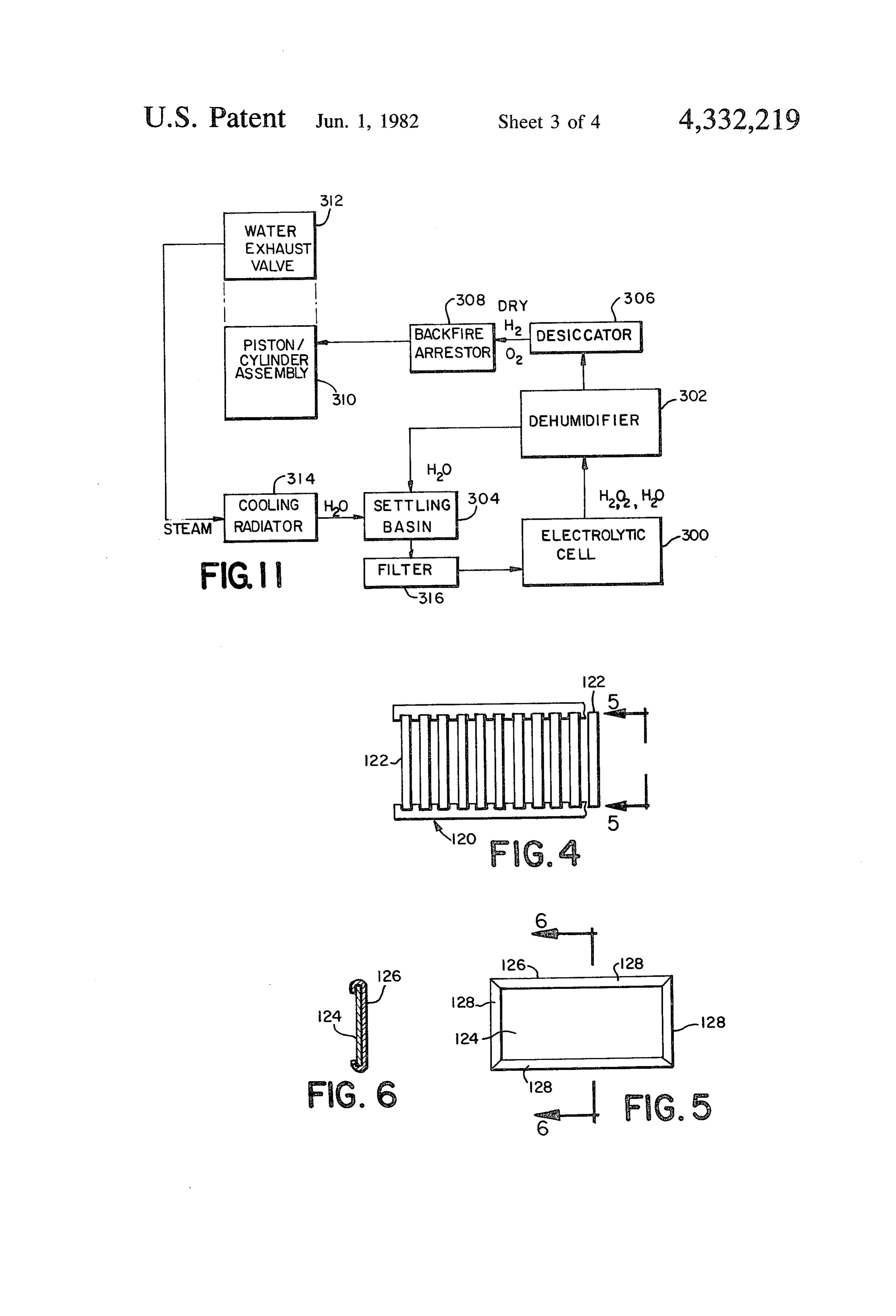
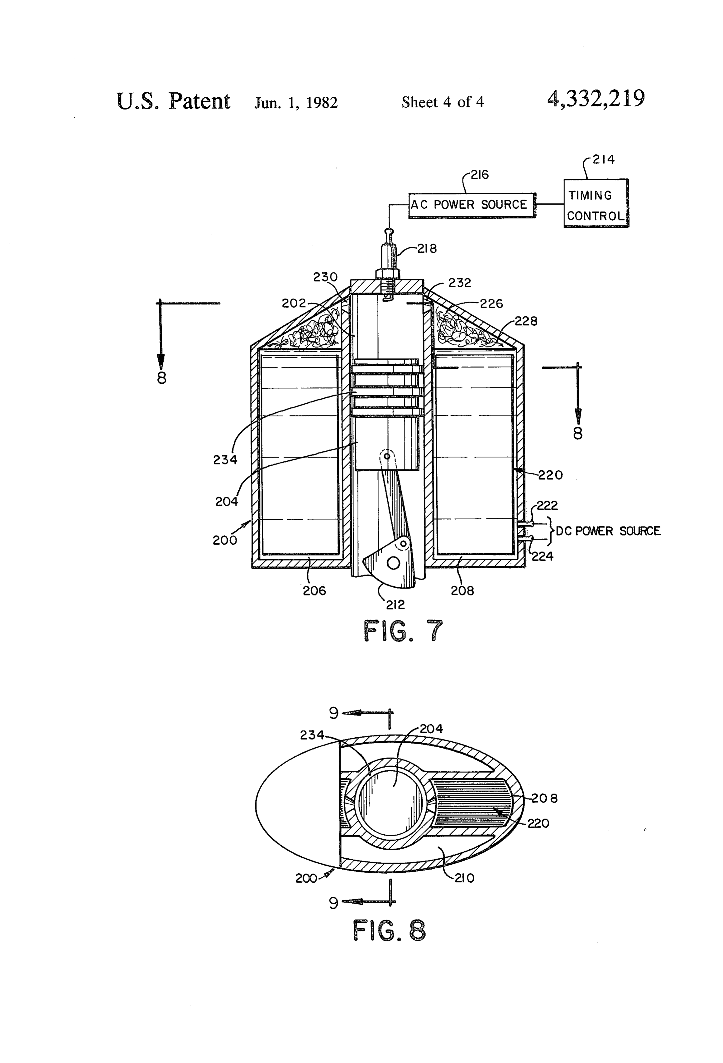
BRIEF DESCRIPTION OF THE DRAWINGS electrolized HyOx to pass therethrough, into the cylin For the purpose of illustrating the invention, there are der. A sufficiently porous sponge material would also shown in the drawings forms which are presently pre be suitable. The electrolytic cell and cylinder are con ferred; it being understood, however, that this invention 10 nected by an input/output port 30. The input/output is not limited to the precise arrangements and instru port 30 is preferably funnel shaped, having its larger end mentalities shown. 32 directed toward the interior of the cylinder, and its FIG. 1 is a substantially diagrammatic representation smaller end 34 directed to the electrolytic cell. The of a reciprocating electro-combustion motor according HyOx mixture is ignited by spark plug 36. A switch 38 to this invention, as used to power a pump; 15 is disposed at the top of the cylinder, mounted therein FIG. 2 is a portion of FIG. 1, with the piston in a between two electrically insulated contacts 40 and 42. different operational position. A bow shaped member 44 has one end thereof flexibly FIG. 3 is a substantially diagrammatic representation mounted to contact 42. The other end is a contact of an electrolytic cell according to this invention; switch, similar to the points of a distributor which FIG. 4 is an enlarged side elevation, partially broken 20 breaks contact with member 40, whenever it is engaged away, of any of the sets of electrodes shown in FIG. 3; by the pistor 14 moving in toward the cylinder, or to the FIG. 5 is a view taken along the line 5-5 in FIG. 4; right with respect to the orientation of FIG. 1. Contact FIG. 6 is a section view taken along the line 6-6 in 40 is connected to the insulated terminal of the spark FIG. 5; plug 36. Contact 42 is connected to the positive terminal FIG. 7 is an electro-combustion engine according to 25 of a high voltage alternating current source. The cylin this invention wherein the reciprocating motion of the der wall, which is made from metal, is connected by a piston is translated into rotary motion; wire 46 to the common terminals of the alternating FIG. 8 is a section view taken along the line 8-8 in current source. A single power source 48 is indicated, FIG. 7; which must supply high voltage alternating current to FIG. 9 is a section view taken along the line 9-9 in 30 the spark plug 36 and direct low voltage current, FIG. 8; through a controller 50, to the electrode plates 22 of the FIG. 10 illustrates an optional valve assembly which electrolytic cell. The power source 48 may be an alter may be disposed between an electrolytic cell and a nating current source, having an AC/DC convertor for piston/cylinder assembly; and, powering the electrolytic cell, or it may be a direct FIG. 11 is a block diagram illustrating more fully the 35 current source having a DC/AC convertor for power operational components of a more sophisticated power ing the spark plug. Such DC/AC convertors are used in system based upon this invention. the electronic ignition systems of most automobiles DETALED DESCRIPTION OF THE produced today, and generally involve the use of a PREFERRED EMBODIMENTS transistor chopping, circuit in conjunction with the pri 40 mary of a transformer. The chopper circuit changes the
This invention, utilized in one of its most elemental DC input to a square wave, which is in effect an alter forms, is shown in FIG. 1. The entire apparatus 10 is a nating current, which can then be stepped up by a tes fluid pump. The fluid pump 10 comprises a cylinder 12 lacoil and used to fire the spark plug. Whenever the in which a reciprocating piston 14 is slideably disposed. piston disengages switch 44, opening the contact Two sealing rings 16 encircle the piston 14. The piston 45 thereof, the spark plug is fired. This occurs in each 14 is essentially free-floating within the cylinder, that is, instance when the piston is at its rightmost position, or is not necessarily connected to anything else. Stops furthest into the cylinder towards the head. formed by protrusions in the inner wall of the cylinder, When a DC current is passed through the electrolytic not shown for purposes of clarification, may be utilized solution, hydrogen and oxygen gases are liberted from to define the inner and outer limits of movement of the 50 the fluid in the cell, at the surface of the electrode piston within the cylinder. plates. These gases rise to the top of the electrolytic cell, An electrolytic cell 18 is provided for electrolizing and pass into the cylinder through the input/output port water, in order to form a combustible mixture of hydro 30. The pressure and volume of gases filling the cylin gen and oxygen gas. This combination of gases has been der is determined by the voltage level at which the termed "HyOx', and will be so referred to hereinafter. 55 electrolytic cell is operated. Certain optimum levels The electrolytic cell 18 is provided with at least one set have been discovered, which will be discussed more 20 of electrodes, and preferably a plurality of such sets. fully hereinafter. Assuming that the apparatus is in an In the presently preferred embodiment, each set 20 of operational condition, at sometime the piston 14 will be electrodes comprises eleven individual bipolar elec moving to the right, and will engage switch 38. When trode plates 22. The middle electrode plate 22n is con 60 contact is cut the spark plug 36 fires, and the HyOx, nected to the positive terminal of a direct current comprising a combustible mixture of hydrogen and source. The two end plates 22e are connected to the oxygen gas, explosively recombines. The force of the negative terminal of the direct current source or the explosion of the recombining gases forces the piston out opposite. The electrolytic solution in the cell is prefera of the cylinder, or toward the left, toward the extreme bly bicarbonate of soda dissolved in water. This solu 65 position shown in FIG. 2. It will be appreciated that the tion is safe to touch, even in the highest concentrations, HyOx formed a certain volume of gas within a very and it is just as effective, if not more effective than other small part of the cylinder immediately prior to ignition. caustic electrolytic solutions which are known and used When the hydrogen and oxygen gases recombine, they
Page 8
form a trace amount of water, as well as a vacuum, as anyhow, eliminating the need for sophisticated cooling the volume of the trace amount of water is very signifi equipment, heat exchangers and the like. It will be ap cantly smaller than the volume previously occupied by preciated that the trace amounts of water, which may the HyOx in the gaseous state. The effect of this vac be partially in the form of steam, will eventually be uum is multiplied by the fact that the piston has been come water and find their way back into the translator, driven in a direction out of the cylinder, so that the flowing through the input/output port 30, where they trace amount of water now occupies not only the origi can be re-dissociated into HyOx. The sealing rings 16 nal volume of the HyOx gases, but a volume which may and the inner surface of the cylinder may be made of or be five times, ten times or more, larger than the original coated with low friction plastic material, such as Tef volume. This very strong vacuum which is created O lon. The components are not subject to damage from forcefully pulls the piston back into the cylinder, in the the HyOx explosion, because there is only enougn oxy direction of the spark plug and switch 38. As the piston gen to burn the hydrogen, as long as care is taken to use is pulled back into the cylinder, further HyOx is also compatible materials.
pulled into the cylinder, so that by the time the piston An alternative embodiment of a more sophisticated once again engages switch 38, there is further explosion 15 electrolytic cell for producing HyOx in accordance which drives the piston outwardly, followed by what is with this invention is illustrated in FIG. 3. This embodi in effect an implosion, as the vacuum draws the piston ment contains many safety devices and monitors, which back up. This explosion/implosion effect has been of course would not be necessary in the normal course termed "EXPIMP' and will be so referred to hereinaf of operation. As in many instances, they are provided in ter. 20 order to prevent dangerous conditions and emergency In most engines which utilize hydrogen gas or the situations. The electrolytic cell 100 comprises a number combination of hydrogen and oxygen gas for use as a of sets 120 of bipolar electrodes, similar to those dia fuel or a fuel additive, the hydrogen and oxygen gas is grammatically illustrated in FIG. 1. The number of sets almost always mixed with air prior to combustion. The utilized will depend upon the power requirements of the combustion of hydrogen and oxygen gas together with 25 particular HyOx engine and the consequent desired air, and perhaps with gasoline, means that a vacuum capacity of the electrolytic cell. An enlarged view of a will not be formed as a result of the combustion process, set of electrodes 120 is shown in FIG. 4. In the presently or in any event, if a vacuum is formed, it will be too preferred embodiment, eleven such bipolar plates 122 weak to have any effect on movement of the piston. The are mounted in each set 120. It is preferable that the vacuum effect is also apt to be dissipated, if present at 30 plates be spaced as closely together as possible, without all, when the exhaust valve opens in the typical four of course touching one another. The closer the plates, cycle engine. In such known engines, the piston returns the less resistance to current flow through the electro to the firing position within the cylinder as a result of lytic solution. As technology permits, separations on either momentum or the firing of other piston cylinder the order of molecular diameters, of water for example, assemblies in a bank of piston cylinder assemblies. Such 35 are anticipated. Each bipolar electrode comprises a mechanisms for returning the piston are not necessary positive and negative plate, one clad around the other. according to this invention, as the piston returns auto This cladding which also could be sprayed or plated is matically and powerfully. It may be desirable to pro further illustrated in FIGS. 5 and 6. The inner electrode vide this apparatus with a means for bringing the piston plate 125 is a simple rectangular sheet. The outer mem back to a starting position, should it misfire in some 40 ber 126 has its perimeter bent around the edges of the fashion or should the vacuum be lost, for example, by inner plate 124, forming a border or frame 128 there improper functioning of the electrolytic cell or missing around. When the electrodes are mounted in rows, the spark plug. exposed surface of the inner plate always faces the back The reciprocating motion of the piston may be di of the cladding plate of the adjacent electrode. It has rectly utilized in the fluid pump illustrated in FIGS. 1 45 been found that this arrangement substantially reduces and 2. During the upstroke of the piston, immediately stray current, and in so doing, reduces the operating preceeding the position of the piston as shown in FIG. temperature of the electrolytic cell and other efficiency 1, fluid, such as air or water, may be drawn into one or wise benefits. It has been found that increases in the more funnel-like inlets 52, as shown by arrows 54. The temperature of the electrolytic cell result in progres end of the cylinder 12 is connected to a discharge pipe 50 sively inefficient operation and lower production levels 56, which has a sealing flap valve 58 hingedly mounted of HyOx and much energy is wasted in just heating the at the end thereof. The upstroke of the piston draws the water. For this we prefer to have a temperature control flap valve 58 closed, so that fluid can be drawn into the switch connected to the heating unit. In one presently inlets 52. When the spark plug is ignited, the piston is preferred embodiment, the outer electrode plate is driven to the position shown in FIG. 2. As it moves in 55 formed from titanium and the inner plate is formed from this direction, flap valve 58 is opened so that fluid can stainless steel. Many different combinations of electrode leave exit pipe 56, as shown by arrow 60. At the same materials may be utilized relating to cathodo-anodic time, due to the funnel shape of the inlets 52, and a relationship with similar results, although the bipolar, venturi effect, keeps the fluid flowing in through the clad overlapped edge arrangement is preferred irrespec inlets. Due to vortices or otherwise, illustrated by ar 60 tive of the choice of materials. rows 62, substantially all of the fluid is forcefully ex A further unexpected result of the experiments which pelled. When the next vacuum is formed, the piston is resulted in this invention is that lower than expected drawn back into the cylinder, closing flap valve 58 and production rates of gases provide a higher return with drawing more fluid in through inlets 52. As the piston respect to the relative cost of energy input than larger reciprocates within the cylinder 14, a steady pulsejet of 65 outputs. Some of this is of course due to heating which fluid may be pumped. Such an arrangement is particu takes place at higher current and voltage levels, which larly suited for use on underwater jet propulsion sys heating impedes the electrolytic process. The following tems for a marine vehicle, as the engine runs very cool chart indicates experimental results of a typical yet
Page 9
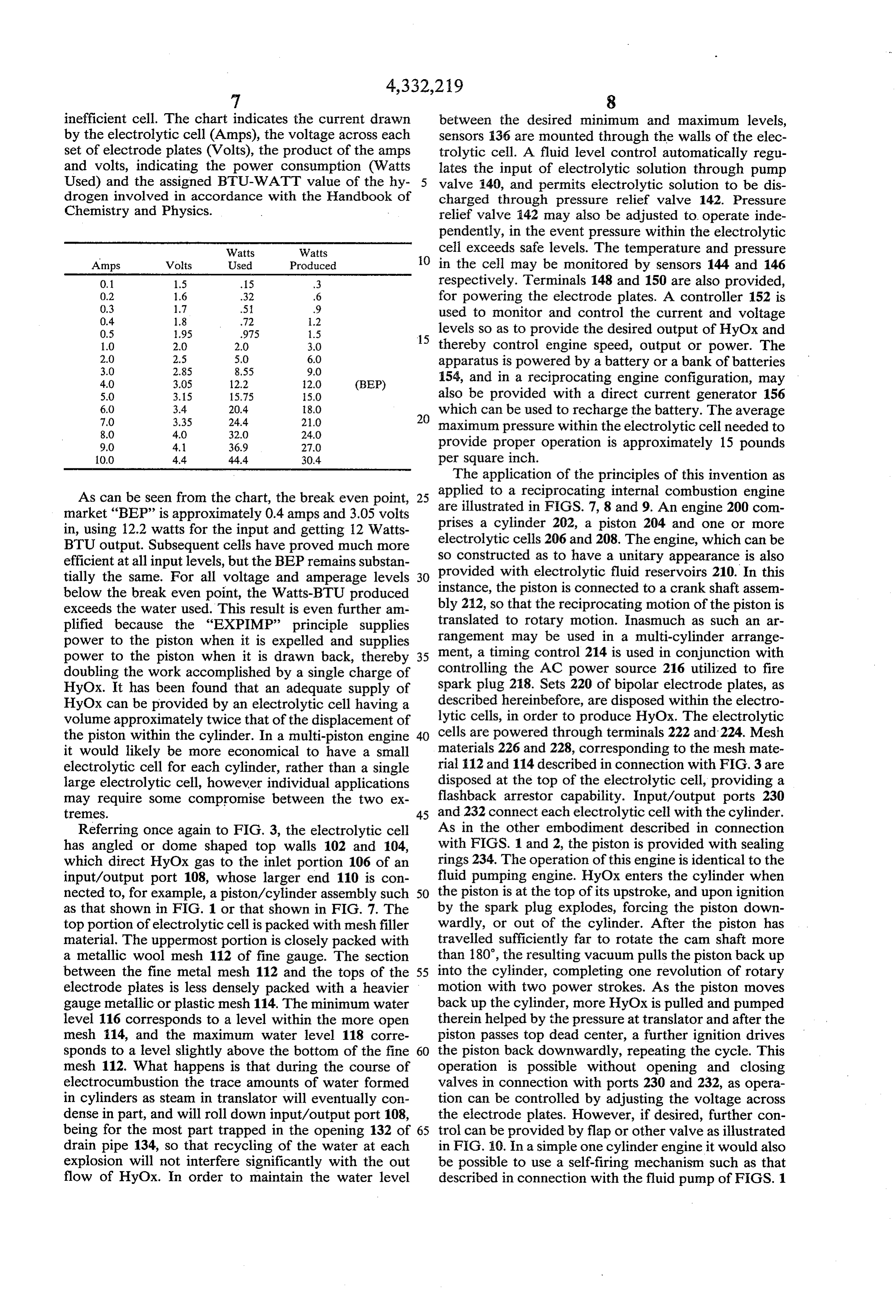
inefficient cell. The chart indicates the current drawn between the desired minimum and maximum levels, by the electrolytic cell (Amps), the voltage across each sensors 136 are mounted through the walls of the elec set of electrode plates (Volts), the product of the amps trolytic cell. A fluid level control automatically regu and volts, indicating the power consumption (Watts lates the input of electrolytic solution through pump Used) and the assigned BTU-WATT value of the hy 5 valve 140, and permits electrolytic solution to be dis drogen involved in accordance with the Handbook of charged through pressure relief valve 142. Pressure Chemistry and Physics. relief valve 42 may also be adjusted to operate inde pendently, in the event pressure within the electrolytic
Watts Watts cell exceeds safe levels. The temperature and pressure
O in the cell may be monitored by sensors 144 and 146
0.1 1.5 .15 3 respectively. Terminals 148 and 150 are also provided,
for powering the electrode plates. A controller 152 is 0.4 1.8 72 1.2 used to monitor and control the current and voltage
levels so as to provide the desired output of HyOx and 1.0 2.0 2.0 3.0 thereby control engine speed, output or power. The
apparatus is powered by a battery or a bank of batteries 4.0 3.05 12.2 2.0 (BEP) 154, and in a reciprocating engine configuration, may 5.0 3.15 15.75 5.0 also be provided with a direct current generator 156
which can be used to recharge the battery. The average 8.0 4.0 32.0 24.0 maximum pressure within the electrolytic cell needed to 9.0 4.1 36.9 27.0 provide proper operation is approximately 15 pounds 10.0 4.4 44.4 30.4 per square inch.
The application of the principles of this invention as
As can be seen from the chart, the break even point, 25 applied to a reciprocating internal combustion engine market "BEP” is approximately 0.4 amps and 3.05 volts are illustrated in FIGS. 7, 8 and 9. An engine 200 com in, using 12.2 watts for the input and getting 12 Watts prises a cylinder 202, a piston 204 and one or more BTU output. Subsequent cells have proved much more electrolytic cells 206 and 208. The engine, which can be efficient at all input levels, but the BEP remains substan so constructed as to have a unitary appearance is also tially the same. For all voltage and amperage levels 30 provided with electrolytic fluid reservoirs 210. In this below the break even point, the Watts-BTU produced instance, the piston is connected to a crank shaft assem exceeds the water used. This result is even further am bly 212, so that the reciprocating motion of the piston is plified because the "EXPIMP' principle supplies rangement tomay translated rotary motion. Inasmuch as such an ar be used in a multi-cylinder arrange power to the piston when it is expelled and supplies power to the piston when it is drawn back, thereby 35 ment, a timing control 214 is used in conjunction with doubling the work accomplished by a single charge of controlling the AC power source 216 utilized to fire HyOX. It has been found that an adequate supply of spark plug 218. Sets 220 of bipolar electrode plates, as HyOx can be provided by an electrolytic cell having a described hereinbefore, are disposed within the electro volume approximately twice that of the displacement of lytic cells, in order to produce HyOx. The electrolytic the piston within the cylinder. In a multi-piston engine 40 cells are powered through terminals 222 and 224. Mesh it would likely be more economical to have a small materials 226 and 228, corresponding to the mesh mate electrolytic cell for each cylinder, rather than a single rial 12 and 114 described in connection with FIG. 3 are large electrolytic cell, however individual applications disposed at the top of the electrolytic cell, providing a may require some compromise between the two ex flashback arrestor capability. Input/output ports 230 tremes. 45 and 232 connect each electrolytic cell with the cylinder. Referring once again to FIG. 3, the electrolytic cell As in the other embodiment described in connection has angled or dome shaped top walls 102 and 104, with FIGS. 1 and 2, the piston is provided with sealing which direct HyOx gas to the inlet portion 106 of an rings 234. The operation of this engine is identical to the input/output port 108, whose larger end 110 is con fluid pumping engine. HyOx enters the cylinder when nected to, for example, a piston/cylinder assembly such 50 the piston is at the top of its upstroke, and upon ignition as that shown in FIG. 1 or that shown in FIG. 7. The by the spark plug explodes, forcing the piston down top portion of electrolytic cell is packed with mesh filler wardly, or out of the cylinder. After the piston has material. The uppermost portion is closely packed with travelled sufficiently far to rotate the cam shaft more a metallic wool mesh 112 of fine gauge. The section than 180°, the resulting vacuum pulls the piston back up between the fine metal mesh 112 and the tops of the 55 into the cylinder, completing one revolution of rotary electrode plates is less densely packed with a heavier motion with two power strokes. As the piston moves gauge metallic or plastic mesh 114. The minimum water back up the cylinder, more HyOx is pulled and pumped level 116 corresponds to a level within the more open therein helped by the pressure at translator and after the mesh 114, and the maximum water level 118 corre piston passes top dead center, a further ignition drives sponds to a level slightly above the bottom of the fine 60 the piston back downwardly, repeating the cycle. This mesh 112. What happens is that during the course of operation is possible without opening and closing electrocumbustion the trace amounts of water formed valves in connection with ports 230 and 232, as opera in cylinders as steam in translator will eventually con tion can be controlled by adjusting the voltage across dense in part, and will roll down input/output port 108, the electrode plates. However, if desired, further con being for the most part trapped in the opening 132 of 65 trol can be provided by flap or other valve as illustrated drain pipe 134, so that recycling of the water at each in FIG. 10. In a simple one cylinder engine it would also explosion will not interfere significantly with the out be possible to use a self-firing mechanism such as that flow of HyOx. In order to maintain the water level described in connection with the fluid pump of FIGS. 1
Page 10
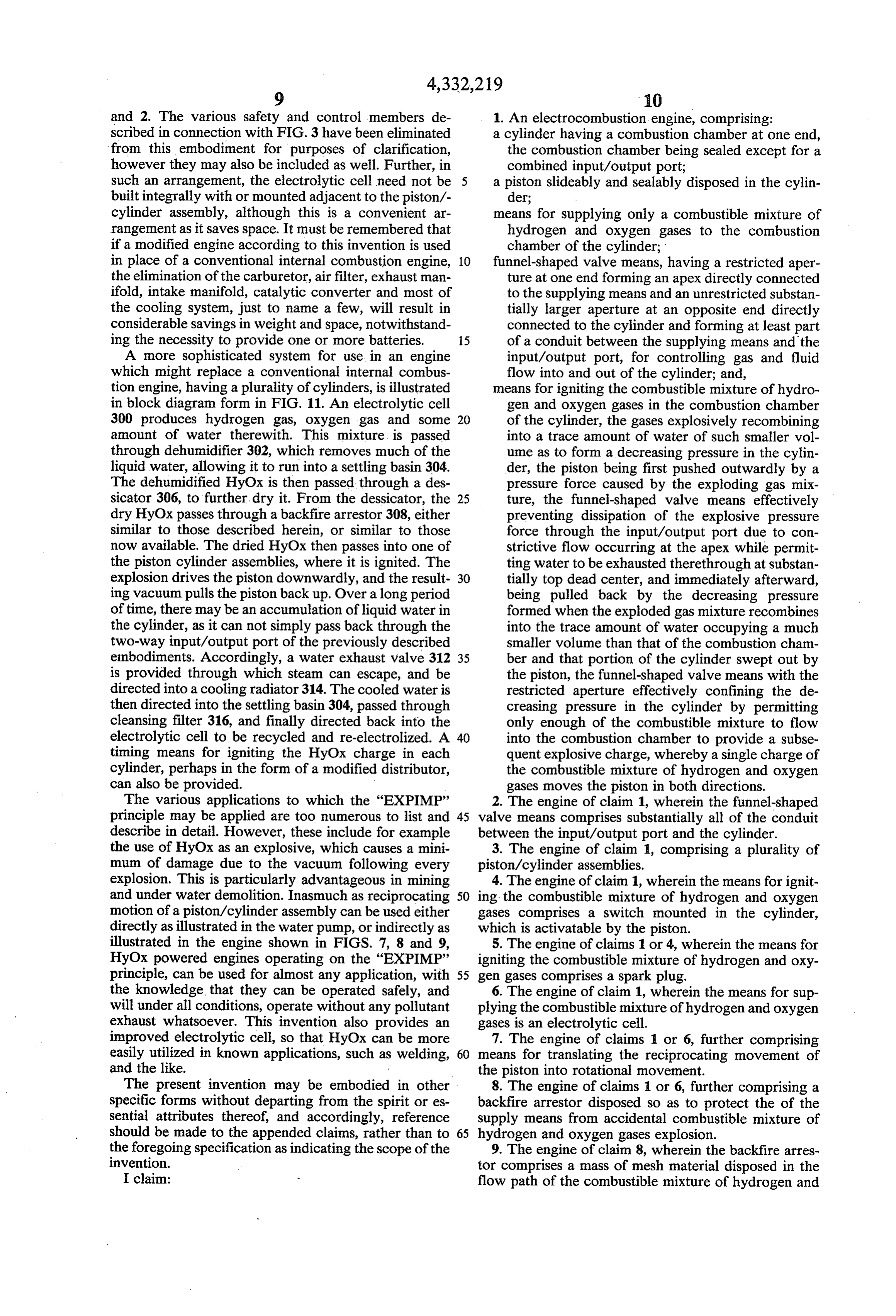
and 2. The various safety and control members de 1. An electrocombustion engine, comprising: scribed in connection with FIG.3 have been eliminated a cylinder having a combustion chamber at one end, from this embodiment for purposes of clarification, the combustion chamber being sealed except for a however they may also be included as well. Further, in combined input/output port; such an arrangement, the electrolytic cell need not be a piston slideably and sealably disposed in the cylin built integrally with or mounted adjacent to the piston/- der;
cylinder assembly, although this is a convenient ar means for supplying only a combustible mixture of rangement as it saves space. It must be remembered that hydrogen and oxygen gases to the combustion if a modified engine according to this invention is used chamber of the cylinder; in place of a conventional internal combustion engine, 10 funnel-shaped valve means, having a restricted aper the elimination of the carburetor, air filter, exhaust man ture at one end forming an apex directly connected ifold, intake manifold, catalytic converter and most of to the supplying means and an unrestricted substan the cooling system, just to name a few, will result in tially larger aperture at an opposite end directly considerable savings in weight and space, notwithstand connected to the cylinder and forming at least part ing the necessity to provide one or more batteries. 15 of a conduit between the supplying means and the A more sophisticated system for use in an engine input/output port, for controlling gas and fluid which might replace a conventional internal combus flow into and out of the cylinder; and, tion engine, having a plurality of cylinders, is illustrated means for igniting the combustible mixture of hydro in block diagram form in FIG. 11. An electrolytic cell gen and oxygen gases in the combustion chamber 300 produces hydrogen gas, oxygen gas and some 20 of the cylinder, the gases explosively recombining amount of water therewith. This mixture is passed into a trace amount of water of such smaller vol through dehumidifier 302, which removes much of the ume as to form a decreasing pressure in the cylin liquid water, allowing it to run into a settling basin 304. der, the piston being first pushed outwardly by a The dehumidified HyOx is then passed through a des pressure force caused by the exploding gas mix sicator 306, to further, dry it. From the dessicator, the 25 ture, the funnel-shaped valve means effectively dry HyOx passes through a backfire arrestor 308, either preventing dissipation of the explosive pressure similar to those described herein, or similar to those force through the input/output port due to con now available. The dried HyOx then passes into one of strictive flow occurring at the apex while permit the piston cylinder assemblies, where it is ignited. The ting water to be exhausted therethrough at substan explosion drives the piston downwardly, and the result 30 tially top dead center, and immediately afterward, ing vacuum pulls the piston back up. Over a long period being pulled back by the decreasing pressure of time, there may be an accumulation of liquid water in formed when the exploded gas mixture recombines the cylinder, as it can not simply pass back through the into the trace amount of water occupying a much two-way input/output port of the previously described smaller volume than that of the combustion cham embodiments. Accordingly, a water exhaust valve 312 35 ber and that portion of the cylinder swept out by is provided through which steam can escape, and be the piston, the funnel-shaped valve means with the directed into a cooling radiator 314. The cooled water is restricted aperture effectively confining the de then directed into the settling basin 304, passed through creasing pressure in the cylinder by permitting cleansing filter 316, and finally directed back into the only enough of the combustible mixture to flow electrolytic cell to be recycled and re-electrolized. A 40 into the combustion chamber to provide a subse timing means for igniting the HyOx charge in each quent explosive charge, whereby a single charge of cylinder, perhaps in the form of a modified distributor, the combustible mixture of hydrogen and oxygen can also be provided. gases moves the piston in both directions. The various applications to which the "EXPIMP' 2. The engine of claim 1, wherein the funnel-shaped principle may be applied are too numerous to list and 45 valve means comprises substantially all of the conduit describe in detail. However, these include for example between the input/output port and the cylinder. the use of HyOx as an explosive, which causes a mini 3. The engine of claim 1, comprising a plurality of mum of damage due to the vacuum following every piston/cylinder assemblies.
explosion. This is particularly advantageous in mining 4. The engine of claim 1, wherein the means for ignit and under water demolition. Inasmuch as reciprocating 50 ing the combustible mixture of hydrogen and oxygen motion of a piston/cylinder assembly can be used either gases comprises a switch mounted in the cylinder, directly as illustrated in the water pump, or indirectly as which is activatable by the piston. illustrated in the engine shown in FIGS. 7, 8 and 9, 5. The engine of claims 1 or 4, wherein the means for HyOx powered engines operating on the “EXPIMP' igniting the combustible mixture of hydrogen and oxy principle, can be used for almost any application, with 55 gen gases comprises a spark plug. the knowledge. that they can be operated safely, and 6. The engine of claim 1, wherein the means for sup will under all conditions, operate without any pollutant plying the combustible mixture of hydrogen and oxygen exhaust whatsoever. This invention also provides an gases is an electrolytic cell.
improved electrolytic cell, so that HyOx can be more 7. The engine of claims 1 or 6, further comprising easily utilized in known applications, such as welding, 60 means for translating the reciprocating movement of and the like. the piston into rotational movement. The present invention may be embodied in other 8. The engine of claims 1 or 6, further comprising a specific forms without departing from the spirit or es backfire arrestor disposed so as to protect the of the sential attributes thereof, and accordingly, reference supply means from accidental combustible mixture of should be made to the appended claims, rather than to 65 hydrogen and oxygen gases explosion. the foregoing specification as indicating the scope of the 9. The engine of claim 8, wherein the backfire arres invention. tor comprises a mass of mesh material disposed in the I claim: flow path of the combustible mixture of hydrogen and
Page 11
oxygen gases, water particles clinging to the mesh stop funnel-shaped valve means effectively preventing ping backfires. dissipation of the explosive pressure force through 10. A method for powering a piston in a piston/cylin the input/output port, due to constrictive flow der assembly, the cylinder having a combustion cham occurring at the apex while permitting water to be ber at one end thereof, comprising the steps of: exhausted therethrough at substantially top dead sealing the combustion chamber except for a com center, and immediately afterward, being pulled bined input/output port; back by the decreasing pressure formed when the supplying only a combustible mixture of hydrogen exploded gas mixture recombines into the trace and oxygen gases to the combustion chamber of the amount of water occupying a volume much smaller cylinder; O than that of the combustion chamber and that por controlling gas and fluid flow into and out of the tion of the cylinder swept out by the piston, the cylinder by passing the combustible mixture funnel-shaped valve means effectively confining through funnel-shaped means, having a restricted the vacuum in the cylinder by permitting only aperture at one end forming an apex directly con enough of the combustible mixture to flow into the nected to the supplying means and an unrestricted 15 combustion chamber via said restricted aperture to substantially larger aperture at an opposite end provide a subsequent explosive charge, whereby a directly connected to the cylinder, and forming at single charge of the combustible mixture of hydro least part of a conduit for the combustible mixture gen and oxygen gases moves the piston in both to the inlet/outlet port; and directions.
igniting the combustible mixture of hydrogen and 20 11. The method of claim 10, further comprising the oxygen gases in the combustion chamber of the step of generating the combustible mixture of hydrogen cylinder, the gases explosively recombining in a and oxygen gases in an electrolytic cell. trace amount of water of such small volume as to 12. The method of claims 10 or 11, further comprising form a decreasing pressure in the cylinder, the the step of translating the reciprocating movement of piston being first pushed outwardly by a pressure 25 the piston into rotational movement. force caused by the exploding gas mixture, the k . k k k
Provenance
- Collection
- Cited prior art
- Original PDF
- patentimages.storage.googleapis.com →
- Filed
- 1980-11-18
- Pages
- 11
- Method
- pdftotext (the PDF's own text layer) + pdftoppm 300dpi page scans
- Source
- Google Patents bibliographic record
- Granted
- 1982-06-01
- Inventors
- Ernesto Gonzalez
- Transcribed from
- patentimages.storage.googleapis.com →