patent · US4599158
Circular coil electrolysis apparatus
8 July 1986
Page 1 — bibliographic record
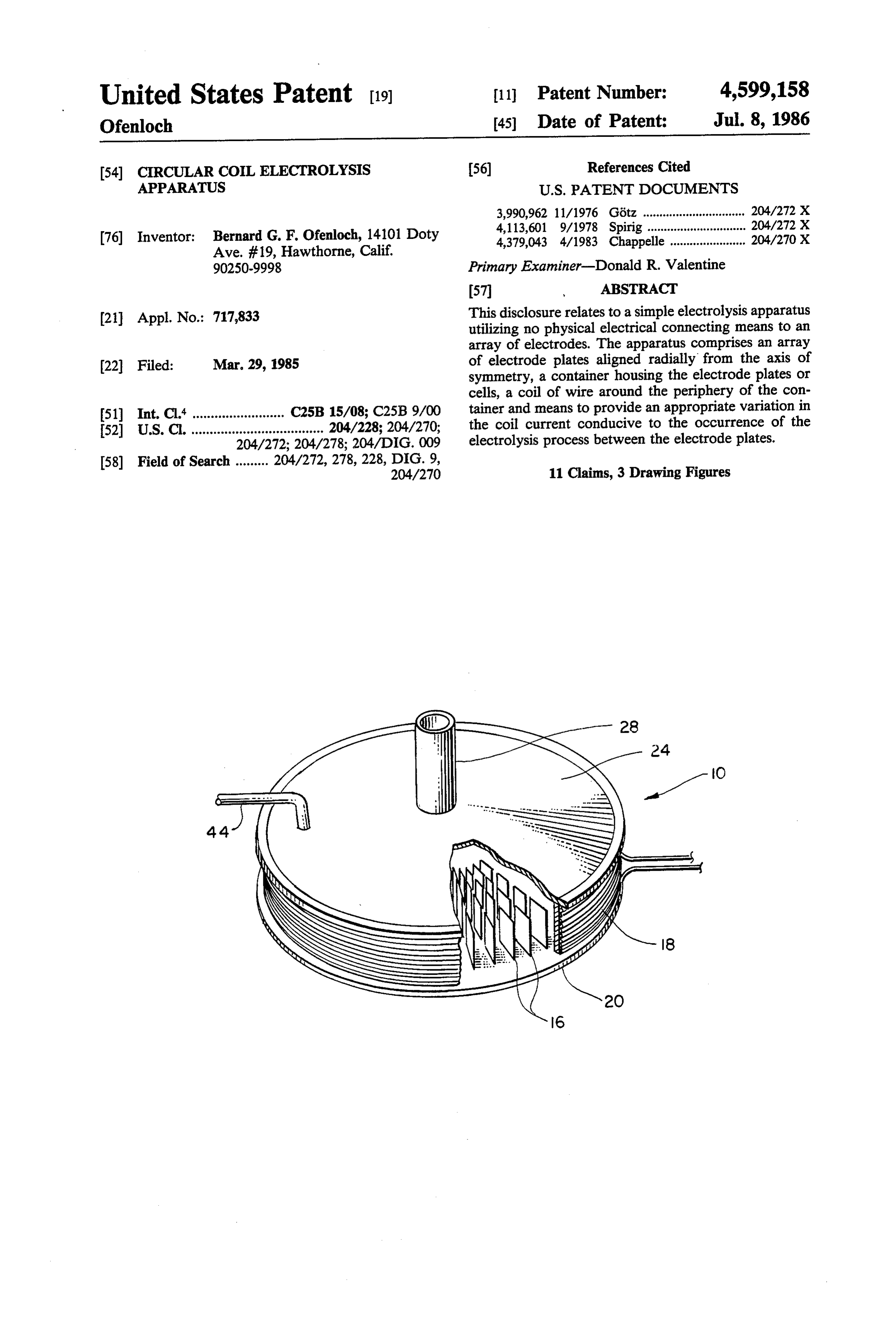
United States Patent (19) 11 Patent Number: 4,599,158 Ofenloch 45 Date of Patent: Jul. 8, 1986 54 CIRCULAR COL ELECTROLYSIS (56) References Cited APPARATUS U.S. PATENT DOCUMENTS 3,990,962 11/1976 Götz ............................... 204/272 X 4,113,601 9/1978 Spirig .............................. 204/272 X (76) Inventor: Bernard G. F. Ofenloch, 14101 Doty 4,379,043 4/1983 Chappelle ....................... 204/270 X Ave. #19, Hawthorne, Calif.
90250-9998 Primary Examiner-Donald R. Valentine
(21) Appl. No.: 717,833 This disclosure relates to a simple electrolysis apparatus utilizing no physical electrical connecting means to an array of electrodes. The apparatus comprises an array 22 Filed: Mar. 29, 1985 of electrode plates aligned radially from the axis of symmetry, a container housing the electrode plates or cells, a coil of wire around the periphery of the con (51) Int. Cl." ......................... C25B 15/08; C25B 9/00 tainer and means to provide an appropriate variation in the coil current conducive to the occurrence of the 52) U.S. C. .................................... 204/228; 204/270; electrolysis process between the electrode plates.
(58) Field of Search ......... 204/272, 278, 228, DIG. 9, 11 Claims, 3 Drawing Figures
Page 2
Drawing sheet — no readable text.
Page 3
number of turns of the coil, the radius of the coil loops
CIRCULAR COIL ELECTROLYSSAPPARATUS and frequency of the coil current. Thus, by varying any of the mentioned parameters
BACKGROUND OF THE INVENTION one can vary the amount of product produced. One 1. Field of the Invention would also consider the relation for the current in an This device relates to an alternate and novel ap inductor with respect to the current frequency. It must also be considered if any type of waveform of the cur proach to the production of gases by electrolysis. One rent could be utilized. It turns out that the waveform to unique and important feature is that no direct physical electrical connection from the power source to the 10 be used must be of an unsymmetric and rectified form (unsymmetric with respect to the period).
electrodes is needed.
2. Description of the Theory The movement of the ions will also be influenced by The production of gases in the electrolysis process is the magnetic field from the current in the coil. The most easily affected by placing two non-corroding elec force experienced by the ions in the solution will be trodes in a diluted electrolytic solution (aqueous potas 15 toward the center of the apparatus. This is accom sium hydroxide for example) and then applying a poten plished by correctly choosing the direction of the cur tial between the electrodes. In the electrolysis of water rent in the coil wire. The net motion of the ions, if no a substantial amount of electrical energy is required to electrodes were present, would be a spiralling toward obtain an appreciable amount of gases. There are sev the center of the apparatus.
eral factors that can influence the rate of production of In conclusion, one would have a fairly simple elec gases at the electrodes. If one were to consider the 20 trolysis apparatus with the only electrical connection electrolysis of water, for example, one could increase being that to the coil. If desired, one could also connect the potential between the electrodes, as long as the the electrodes to the power supply to supplement the resistance remained constant. There is one pound of electromotance between the electrodes due to the oscil hydrogen produced per 12,060 ampere-hours. For solu 25 lating magnetic field. Also, there is no motion of any tions at 25 C., 1.229 Volts is the minimum theoretical part of the apparatus to be concerned with. Depending energy requirement that can be measured as an applied upon the electrode or coil size desired, the fields be voltage (giving 14.9 KWH per pound of hydrogen). A tween the electrodes could be considered fairly uni perfect cell would operate at this voltage and energy form.
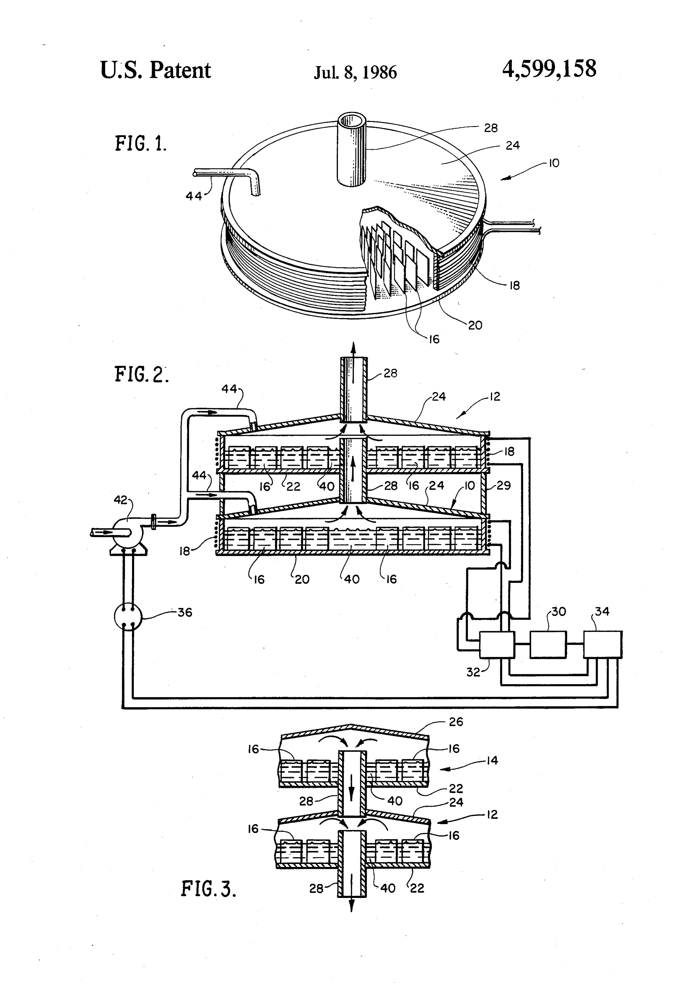
input but would require an additional input of thermal 30 energy equivalent to another 3.1 KWH per pound of BRIEF DESCRIPTION OF THE DRAWINGS hydrogen. In order to provide all the necessary energy FIG. 1 is a perspective view of a singular unit of the as electrical energy, the corresponding voltage is 1.483 electrolysis apparatus.
Volts (for 18.0 KWH per pound). Another method to FIG. 2 is a sectional view showing several electroly increase the rate of production of the gases would be to 35 sis units arranged one on top of the other with exhaust heat the electrolytic solution while maintaining the tubes allowing the gases produced to exit in an upward required potential between the electrodes. direction.
To increase the rate of production of gases one could FIG. 3 is a partial sectional view showing several also increase the conductivity of the solution in order apparatuses arranged one on top of the other with the for the ions in solution to move more freely between the 40 gases produced exiting in a downward direction. electrodes. One could also increase production by in creasing the surface area of the electrodes. SUMMARY OF THE INVENTION A method of increasing the movement of the ions to the anode and cathode by inducing more of a potential apparatus for therelates
This invention to a fairly simple and improved production of gases by electrolysis.
between the electrodes will be examined. The ion 45 One embodiment of the invention could be the electrol movement could be increased by the introduction of an ysis of water.
oscillating magnetic field. This would induce an elec An object of this invention is to provide a means to tromotance as is shown by one of Maxwell's equations: produce gases by electrolysis which could utilize a large E=-d/dt Bida, aggregate surface area.
50 It is also an object of this invention whereby one has where E is the induced electromotance, B is the mag direct a number of electrolysis cells in the apparatus without a netic field vector and da is the differential area element connection to a power supply implementing Vector. wires or other such physical electrical connections. A design to utilize this principle would be to employ This invention for an electrolysis apparatus provides a cylindrical circular coil or solenoid. An oscillating 55 a means whereby the rate of production of the gases can current in the coil wire would cause the magnetic field be controlled or affected in a variety of ways commen around the coil or solenoid to oscillate also. The design surate This with the particular application desired.
invention for an electrolysis apparatus could be of this invention will only be concerned with the fields inside the coil. arranged with other apparatuses of the type of this In the plane of the individual current loops, a circular 60 invention to facilitate an increased production of the oscillating electric field is induced in this case. One gases by utilizing a larger aggregate electrode surface takes advantage of this induced electric field by placing area.
cells of electrodes along the direction of the magnetic Referring to FIG. 1, an electrolysis unit is generally field perpendicular. The existing electromotance will designated reference number 10 with a section cut away cause a movement of the ions in the electrolytic solution 65 to reveal the non-corroding electrode plates 16 ar to the respective anode and cathode of the cells. The ranged within in a circular pattern at various radii from magnitude of the electromotance will be proportional the axis of symmetry. The electrodes 16 are placed in to the product of the magnitude of the coil current, the slots or attached using some method of bonding to the
Page 4
electrically non-conducting base of the container 20. type where it would derive its power through the use of The coil of wire 18 is wound or placed around the a pulley system.
periphery of the electrically non-conducting container FIG. 3 illustrates an embodiment in which the elec 20 with the desired number of turns. The container 20 trolysis apparatuses 12 and 14 could be arranged in may or may not be of one piece and should also have the order to have the gases produced exit through the pipes property of being magnetically permeable. 28 in a downward direction as indicated be the arrows. A shallow cone-type cover 24 for the electrolysis The pipes 28 are inserted through the container base 22 apparatus unit 10, also composed of a non-corroding of unit 14. The cover 26 would be closed at its apex and material, is attached to the unit cover 24 to direct the the covers for the lower unit 12 would be those num gases to a tube or pipe 28 to where they are desired. The 10 bered 24 as is also indicated in FIGS. 1 and 2. gas flow away from the interior of the apparatus 10 is DESCRIPTION OF THE PRIOR ART illustrated by the arrows directed to the central tube 28.
The cover 24 should be attached to the electrolysis U.S. Pat. No. 3,954,592 issued to S. Horvath on May apparatus 10 in a manner so that it could be easily re 15 4, 1976 for an Electrolysis Apparatus teaches a method and apparatus for the production of hydrogen and oxy moved for periodic inspection of the interior of the gen gas. The current for carrying on the electrolysis apparatus. A tube or pipe 44 would be utilized to direct process is provided by a transformer inside the anode the flow of water or electrolytic fluid through the cover 24 to the interior of the apparatus 10. and the pulsing of the electrode cathode at a rapid rate FIG. 2 illustrates an embodiment where the electrol increases the current available for the electrolysis pro 20 CSS ysis unit of type 12 is mounted above the unit of type 10. The invention for an electrolysis apparatus that this Other embodiments could be imagined whereby several patent application is concerned with has no direct elec units of type 12 could be mounted above the apparatus trical contact 10. Tubes or pipes 28 would be placed along the axis of a transformer with the electrodes nor any direct use of symmetry of these apparatuses 10 and 12 with the gases 5 lar type of amplifierthan other
may be existing in the particu the current from the waveform exiting upward as directed by the arrows through these generator employed. The apparatus of S. Horvath is centrally placed tubes 28. The arrangement of these also a rather complicted device where complicated units 10 and 12 would be supported by means of the machining procedures would have to be employed. His supports 29 placed or attached near the periphery of apparatus also utilizes rather high electrical currents and between the two apparatuses 10 and 12. The means which could be potentially dangerous if the user did not to make the arrangement of units 10 and 12 function are exercise utmost caution. The Circular Coil Electrolyis also depicted. Apparatus is a much simpler device and not dangerous The oscillating, unsymmetric and rectified wave form as everything is housed in a container. The signal ampli of the current to the electrolysis apparatuses 10 and 12 fier could be of any type currently available to industry would originate from the waveform generator 30. The 35 as well as the general public. One would also have output current from the waveform generator 30 could access to any type of wave or signal generator, with be amplified by means of an amplifier 32. The amplifica equal ease of availability as well of the pumping means tion unit 32 would have a means to vary the current to and potentiometer. The current in the Circular Coil the coils 18 of the units 10 and 12 and could be one of Electrolysis Apparatus is not pulsed but varies accord several types commercially available depending upon 40 ing to an oscillating and non-symmetric waveform and one's particular application. The waveform generator the voltage is that of the power source and thus is as 30 would draw its power from a power supply 34 as stable as that particular source of power. The current would the amplifier 32 also, which, depending upon the used need not be direct but could also be alternating if type of waveform generator 30 or amplifer 32 used, desired.
could be of a direct or alternating current variety. 45 U.S. Pat. No. 3,522,162 issued to R. L. Davies on July As the electrolytic fluid 40 is depleted, a pumping 28, 1970 on Electrolytic Reactions Under the Influence means 42 would be implemented to insure a continuing of Magnetic Field also teaches a method and apparatus supply of the fluid 40 to the units 10 and 12. The pump to cause the migration of ions or electrically charged ing means 42 could be of any type currently available particles in a solution by passing a body of solution for commercial or domestic use. The arrows from the SO through and cutting a magnetic field. The invention pump 42 illustrate the direction of fluid flow. For an uses a sawtooth current generator to generate a pulse electrical pumping means 42, a potentiometer 36 or wave form which is applied to effect a magnetic field to other means to regulate current flow to the pump 42 cause motion of the ions mainly in one direction. would be implemented to regulate the rate of flow of Although this apparatus utilizes a magnetic field, the the electrolytic fluid 40 from the pump to the electroly 55 Circular Coil Electrolysis Apparatus does no require sis apparatuses 10 and 12. The potentiometer 36 may be the motion of any part of the apparatus. Thus, one need implemented in conjunction with the frequency control not be concerned with the wearing out of bearings and of the waveform generator 30 so that the frequency of bushings with time and use. The magnetic field is gener the current is increased and the flow of the fluid 40 to ated by utilizing a pair of electromagnets whereas with the units 10 and 12 is also increased. The potentiometer 60 the Circular Coil Electrolysis Apparatus (CCEA) a 36 may also be implemented in conjunction with the current through one coil suffices. Again, this device output control of the amplifier 32 so that as the output would also require rather involved machining and as current is increased, the amount of gases produced is sembly procedures not at all necessary with the CCEA. increased and the current to the pumping means 42 is This device also has a physical electrical connection increased thereby increasing the rate of flow to the 65 with the power source which is not necessary with the apparatuses 10 and 12. If the arrangement of the units 10 CCEA.
and 12 is to be used for an internal combustion type U.S. Pat. No. 4,184,391 issued to K, Inoue on Jan. 22, engine, the pumping means 42 could be of a mechanical 1980 on a Method of Electrolytically Generating Hy
Page 5
drogen and Oxygen For Use In A Torch or the Like. the simplicity and practicality of the apparatus and thus This patent teaches a pulse wave form for alternately it could have a wide variety of embodiments as opposed connecting and disconnecting the direct current across to the other apparatuses. One embodiment of this appa the electrodes so as to pass a pulsed electrolyzing cur ratus could be in the operation of internal combustion rent between the electrodes with adjusted pulse dura type engines. In this instance, the power source could tion and interval. be the direct current battery that is currently used in This device uses cylindrically shaped electrodes con automobiles. The battery could be recharged to some nected to a pulsing wave supply. CCEA utilizes plate extent by an alternator or generator as well as some electrodes not connected to a power supply and does turbine type device that would be driven by the exhaust not need a pulsed waveform with a limited range of 10 gases. It is conceded that these methods of recharging operation as is indicated in the patent. would probably not be sufficient but the price of re U.S. Pat. No. 4,297,184 issued to C. K. Dyer on Oct. charging the battery using a "trickle type' charging 27, 1981 for a Method of Etching Aluminum teaches the device on the battery when the CCEA is not in use and use of uneven waveforms in the electrolytic etching of the convenience of utilizing water would be rather aluminum foil. 15 small compared to the rising costs and dangers of hy
The waveform for the just mentioned invention can drocarbon based fuels. This CCEA would also be quite be used in the CCEA upon rectification but is not re safe for use as only that amount of gases produced stricted to using just those waveforms. As was indicated would be immediately utilized in an internal combustion in the "Background of the Invention' section, any recti engine which would also negate the need to store the fied waveform that is unsymmetric with respect to half 20 hydrogen its period could be used. The time to rise to the peak stored untiland use oxygen gases. The only substance to be would be the water itself. Also, one has current must not equal the time to fall to zero current no need for concern and is the only rquirement for the coil current in the only byproduct of theofcombustion environmental damage as the process would be
CCEA,
U.S. Pat. No. 4,105,528 issued to S. Hasebe, et al. on 25 water. Another use of this apparatus would be in the Aug. 8, 1978 for an Apparatus for Decomposition of desalinisation of sea water. In this application, on any Aqueous Liquid teaches an apparatus for decomposi scale, one would supply the initial power to electrolyse tion of liquid in which negative and positive electrodes the sea water and then combine the hydrogen and oxy are arranged in a closed relation and the electrolyte is gen gases utilizing an internal combustion engine or placed to flow between the negative and positive elec 30 other means. The power thus generated from the com trodes under the function of a potential magnetic field bustion of the gases could be used to assist or augment formed by the coil current generated by the electrodes the power input to one or more of the CCEAs. from the active movement of an electrolytic ion so that For this apparatus the use of a circular coil is not the electrolysis of water takes place smoothly. necessary as one could also implement ellipsoidal, rect The electrodes are arranged in a rather complicated 35 angular, etc. designs also, fashion and are directly connected to a power supply In conclusion then, one has a simple apparatus for the with the magnetic field derived from the coil shape of process of electrolysis with the features of varying the the electrodes and permanent magnets located above production of the gases in a variety of manners. These and below the coiled electrodes. Again, the CCEA uses capabilities then render the CCEA far more advanta no permanent magnets and no direct physical connec 40 geous and desirable than the other prior art apparatuses tion between the electrodes and the power source. for almost any application it could be utilized for. U.S. Pat. No. 3,969,214 issued to Mack Harris on July What is claimed is:
13, 1976 for a Permanent Magnet Hydrogen Oxygen 1. An electrolysis apparatus for the production of Generating Cells. This patent teaches a generating coil gases from an electrolytic type fluid comprising, in for hydrogen and oxygen utilizing permanent magnets 45 combination:
and electromagnets. Means are provided for removing electrode plates arranged in a circular fan-type array gases from the electrodes and mixing chambers are at varying distances from the center of the appara provided for water and the electrolyte used in the cell. tus such that the plane of each electrode plate is This patent utilizes permanent magnets and electro perpendicular to the plane of an imaginary circular magnets to give rise to the magnetic field and is also a 50 disk centered on the axis of symmetry of the array; rather complicated device which would necessitate a containing means for housing the electrode plate involved machining and assembly processes. This pa array;
tent also has its electrodes directly attached, by wire a coil of wire is placed about the periphery of said means, to the power supply. This device utilizes sulfuric containing means or the electrode plate array. acid (H2SO4) which could be potentially dangerous 55 2. An electrolysis apparatus in accordance with claim when not handled with appropriate caution. A burner 1 utilizing no direct physical electrical conducting to heat the H2SO4 and water is used which is not at all means to the electrode plates. required in the CCEA. The motion of several parts of 3. An electrolysis apparatus in accordance with claim this apparatus is necessary which would cause one to be 2 whereby said containing means comprises a covering concerned with wear and fatigue of the device. 60
A feature of the CCEA that is rather unique and very means to direct the gases produced away from the appa practical as opposed to the devices of the prior art is ratuS.
that many of the apparatuses could be arranged one on 4. An electrolysis apparatus commensurate with top of the other in order to increase the surface area for claim 2 comprising a feature whereby the electrolysis the electrolysis process and thus increase the produc 65 apparatus is arranged in conjunction with other like tion of gases. apparatuses utilizing a means to conduct the gases pro The features mentioned here, in the "Summary of the duced by electrolysis along a common axis of symmetry Invention' and in the "Specifications' clearly indicate through the base of each apparatus; and
Page 6
the lowest or beginning apparatus will possess no corroding, magnetically permeable and electrically in conducting means, for the gases produced, through sulating type material.
its base. 8. An electrolysis apparatus according to claim 7 that 5. An electrolysis apparatus comensurate with claim utilizes a means to provide a continuing flow of electro lytic fluid or water to the apparatus whereby the fluid 2 comprising a feature whereby the electrolysis appara flow can be varied as desired.
tus is arranged in conjunction with other like appara 9. An electrolysis apparatus in accordance with claim tuses utilizing a means to conduct the gases produced by whereby a current is passed through the coil wire electrolysis along a common axis of symmetry through which will vary periodically and have an unsymmetric the base of each apparatus; and O and rectified type waveform with respect to a represen the uppermost or beginning apparatus will possess no tative period.
conducting means, for the gases produced, through 10. An electrolysis apparatus in accordance with its covering means. claim 9 whereby a means to amplify the waveform 6. A container for an electrolysis apparatus in accor power is implemented.
dance with claim 2, comprises a cover with removeable 15 11. An electrolysis apparatus in accordance with means for the periodic inspection of the apparatus inte claim 1 utilizing a means whereby the electrical current rior. in the coil and the frequency of the waveform imple 7. An electrolysis apparatus in accordance with claim mented can be varied.
3 or claim 2 whereby said containing means is of a non s s s k
Provenance
- Collection
- Cited prior art
- Original PDF
- patentimages.storage.googleapis.com →
- Filed
- 1985-03-29
- Pages
- 6
- Method
- pdftotext (the PDF's own text layer) + pdftoppm 300dpi page scans
- Source
- Google Patents bibliographic record
- Granted
- 1986-07-08
- Inventors
- Bernard G. F. Ofenloch
- Transcribed from
- patentimages.storage.googleapis.com →