patent · US20110094458A1
System to dynamically vary the volume of product gas introduced into a hydrocarbon combustion process
28 April 2011
Page 1 — bibliographic record
(19) United States (12) Patent Application Publication (10) Pub. No.: US 2011/0094458 A1
Dee et al. (43) Pub. Date: Apr. 28, 2011 (54) SYSTEM TO DYNAMICALLY VARY THE Publication Classification
VOLUME OF PRODUCT GAS INTRODUCED
INTO A HYDROCARBON COMBUSTION (51) Int. Cl.
PROCESS FO2B 43/08 (2006.01)
(75) Inventors: John Dee, Cheltenham (AU); Steve (52) U.S. Cl. ............................................................ 123A3 Fulton, Mornington (AU); Dan
Kujawski, Bloomington, MN (US); (57) ABSTRACT
Jason D. Tuzinkewich,
Minneapolis, MN (US) The Combustion Management System models each hydro carbon combustion application and Supplies a product gas, (73) Assignee: GEO Firewall Sarl, Luxembourg comprising a dynamic mixture of nascent hydrogen (H) and (LU) oxygen (O), to the internal combustion engine to propagate the formation of hydroxide radicals (OH) and thereby to (21) Appl. No.: 12/877,026 improve the level of completion of the hydrocarbon combus tion reaction. The Combustion Management System provides (22) Filed: Sep. 7, 2010 product gas Volumetric requirement information; and takes Related U.S. Application Data into account the engine style, primary torque requests, and hydrocarbon fuel consumption information to develop an (60) Provisional application No. 61/241,783, filed on Sep. operating system specific application that produces consis 11, 2009. tent measurable results.
REACTORCELL
POWERSWITCH
S REACTORCELL
TRANSPORT INPUT
CONTROLLER SOENOID 205
PUMP;
SOLENOID
S> DRIVE
OLLER
SENSOR POWER FLUID DATABASE
PROCESSOR MEMORY MONITOR CONTROL CONTROL MANAGER 221 222- 226 22s) 224 22a
Page 2
Patent Application Publication Apr. 28, 2011 Sheet 1 of 6 US 2011/0094458A1
HYDROCARBONFUEL PRODUCT GAS REACTORCELLS
THROTTLE SETTING CONSUMED REQUIRED ACTIVATED
FIG. 1A
100% Fuel Input
20.6% Exhaust|Heat 3.9% LOSt
9.0% Stored Energy \--- 12.3%. Water 42.9% Mechanical
FIG. 1B
Page 3
Patent Application Publication Apr. 28, 2011 Sheet 2 of 6 US 2011/0094458A1
FROM 610
REACTOR CELL
POWER SWITCH
SdCATALYST
INPUT
FLOW
PUMP
N. A?ia PUMP 204
REACTOR CELL
GAS
SCRUBBER
UNIT
CONTROLLER SOENOID 206
S> DRIVE
CONTROLLER
SENSOR
MONITOR
Page 4
Drawing sheet — no readable text.
Page 5
Patent Application Publication Apr. 28, 2011 Sheet 4 of 6 US 2011/0094458A1
FIG. 4A
Normal Plate
30% Plate Current Spread on Square Plate Generates leSS reactive Surface
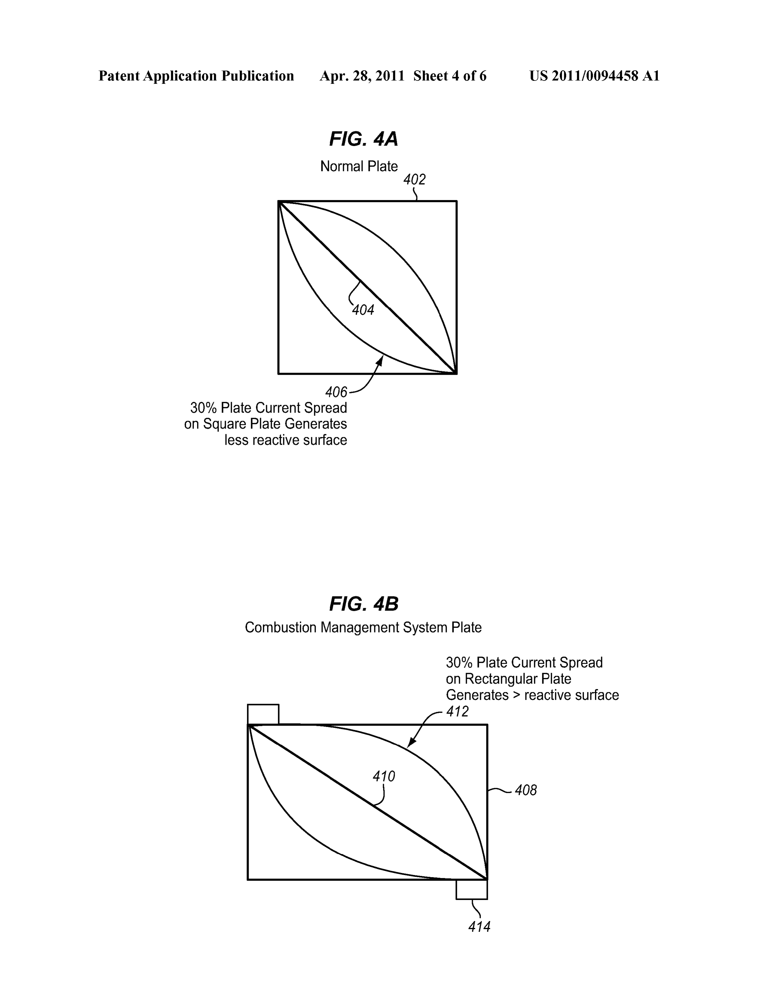
FIG. 4B
Combustion Management System Plate 30% Plate Current Spread on Rectangular Plate
Generates > reactive Surface
Page 6
Drawing sheet — no readable text.
Page 7
Drawing sheet — no readable text.
Page 8
US 2011/0094458 A1 Apr. 28, 2011
SYSTEM TO DYNAMICALLY VARY THE market Success as a result of fuel cost and Scarcity. In the end, VOLUME OF PRODUCT GAS INTRODUCED fossil fuels (petroleum) won out as the primary mechanical INTO A HYDROCARBON COMBUSTION fuel Source, and hydrogen was all but forgotten in this arena. PROCESS 0006. The military mobilization efforts leading up to World War I saw a German force confronting petroleum fuel
CROSS-REFERENCE TO RELATED scarcity issues. Engineers decided that their best option was APPLICATIONS to utilize hydrogen to create a hybridized fuel using the bitu 0001. This patent application claims priority to U.S. Pro minous fuels of which they had plenty, and Hydrogen visional Patent Application Ser. No. 61/241,783 filed on Sep. Enhanced Combustion (HEC) was born. By the end of the 11, 2009. This application is also related to applications filed war, the dubious results produced by HEC attempts and a on the same date titled “System For Increasing The Level Of sharp decline in the need to pursue this approach led to a relative cessation of research in this field.
Completion Of Diesel Engine Hydrocarbon Combustion':
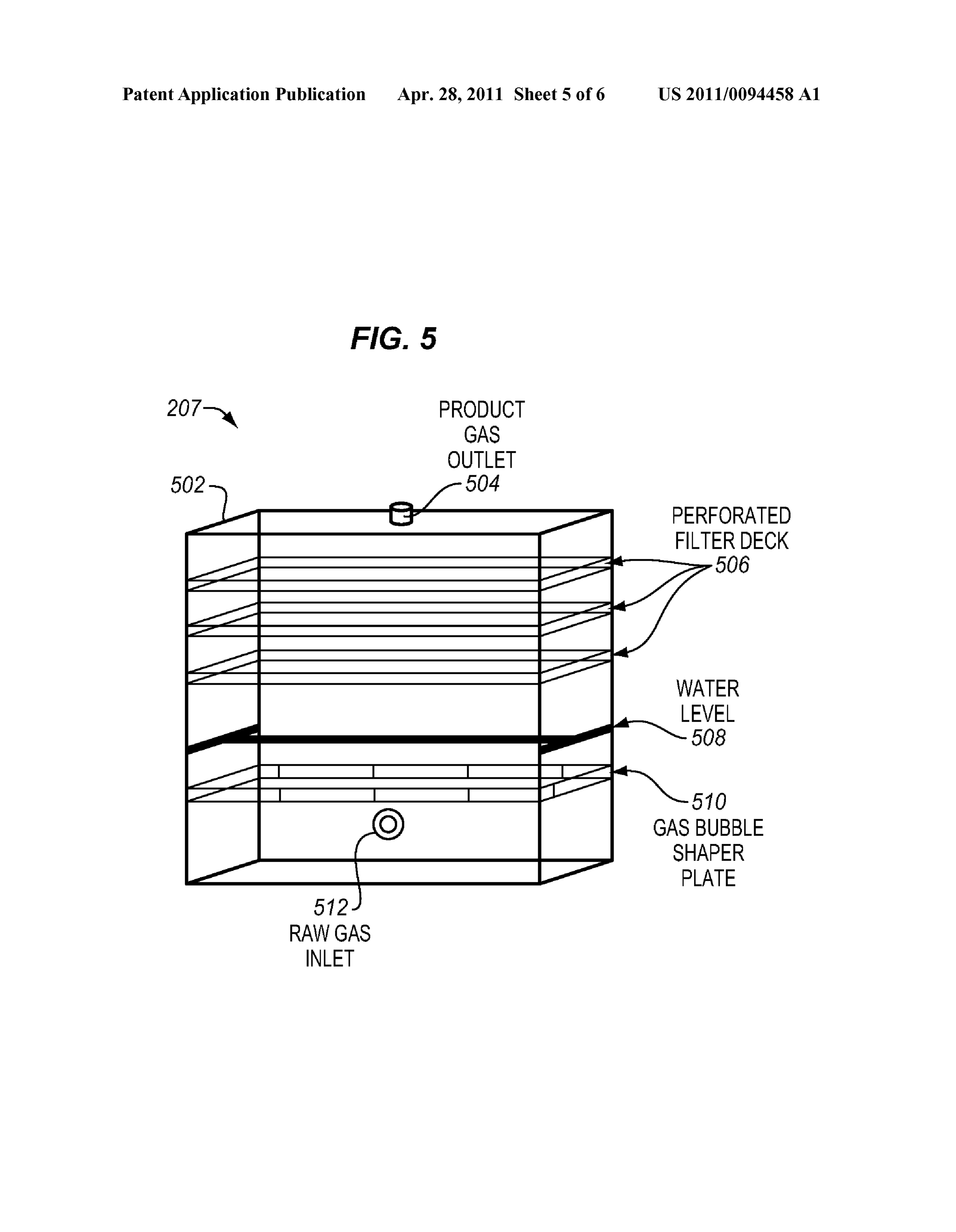
“System For Regulating A Hydrocarbon Combustion Process 0007. The petroleum supply crisis of the 1970's marked the second wave of interest in HEC research. This wave was
Using A Substantially Stoichiometric Mix. Of Hydrogen And largely a garage movement and sparked a shift in the produc Oxygen”; “Product Gas Generator For Producing A Substan tion of hydrogen and its application within the internal com tially Stoichiometric Mix. Of Hydrogen And Oxygen: “Sys bustion engine. Electrolysis as a means for onboard gaseous tem. For Producing A Substantially Stoichiometric Mix. Of hydrogen generation was the process favored by the HEC Hydrogen And Oxygen Using A Plurality Of Electrolytic
Cells'; and “Regulating A Hydrocarbon Combustion Process hobbyist, and several advances were made in the realm of Using A Set Of Data Indicative Of Hydrocarbon Fuel Con electrolytic decomposition of water. Meanwhile, fossil fuel Sumed Corresponding To A Monitored Engine Operating reformation was the common mechanism employed by the Characteristic.” The foregoing applications are hereby incor Scientific community as a more efficient means to a higher porated by reference to the same extent as though fully dis yield for gaseous hydrogen generation. This technology also closed herein. saw marked advances in efficiency. Learning from the issues with the earlier German studies, gaseous hydrogen was
FIELD OF THE INVENTION administered as a separate entity, either directly injected into the cylinders of the internal combustion engine or mixed with 0002 This system controls the operation of a hydrocarbon the engine's air Supply.
consuming process to improve the level of completion of the 0008. As petroleum supplies again became more acces hydrocarbon combustion reaction by injecting a dynamically sible, the interest in HEC experienced a decline until recent generated mixture of nascent hydrogen and oxygen into the environmental awareness met with forecasts of fossil fuel combustion air to propagate the formation of hydroxide radi depletion to promote a Surge in the hydrogen economy move cals, thereby promoting a higher degree of oxidative comple ment. Many companies were formed to promote products tion, and extracting more energy from the fuel and reduce the similar to those touted for their successes in the 1970's, mak level of unburned hydrocarbons in the combustion exhaust. ing extraordinary claims with respect to fuel savings and
BACKGROUND OF THE INVENTION
emissions reductions. Despite all of the claims, no govern ment agency has approved such a technology to date. Mean 0003. It is a problem to increase the fuel efficiency of while, internal combustion engine manufacturers and internal combustion engines. In particular, enhancing the effi research institutions alike have been working with renewed ciency and fuel Versatility of internal combustion engines by effort and expanded budgets to achieve marketable Successes introducing hydrogen into the system is a pursuit that has with hydrogen. The majority of this community has focused vexed engineers since the beginning of the 20' Century. its resources on fuel cell technology, deeming the difficulties Interest in this pursuit has been inconsistent over the years, in applying HEC to the internal combustion engine to be taking a back seat due to the difficulties in achieving consis prohibitive. A handful of research institutions have conducted tency in Successes, yet gaining Support, but not success, dur studies, with limited Success, ultimately agreeing that the ing times of fuel Scarcity and Social environmental focus. difficulties outweigh the potential gains. 0004. The methods of introducing hydrogen into the inter nal combustion engine have varied widely from hydrogenat Hydrogen Enhanced Combustion Model ing bituminous fuels to administering gaseous hydrogen into 0009. The original model for Hydrogen Enhanced Com the internal combustion engine's air Supply. Theoretical com bustion was predicated upon preparing bituminous fuels to be putations have Suggested the potential for gains in combus usable in internal combustion engines. To this end, the fuel tion efficiency on many levels, but the practical application was actually hydrogenated at a processing facility, and then has been dubious, yielding just the slightest glimpse of these shipped and stored in this hydrogenated form. The major theoretically possible combustion efficiency gains. The fol complication in this process was the inherent stability of the lowing description discusses several of these practical appli resultant fuel. The hydrogen became so stable in this format cations with a focus on the theory and variables responsible that many of the theoretical attributes which made hydrogen for inconsistencies or negative results. originally enticing were not realized in the cylinders of the internal combustion engine. This stability issue manifested
Hydrogen in History itself in the form of sluggish response and chronic backfiring 0005 Hydrogen was first suggested as a fuel for machin of the internal combustion engine. ery in 1820 by W. Cecil's treatise, “On the application of Hydrogen Replacement Model hydrogen gas to produce a moving power in machinery.”
Several incarnations of hydrogen-powered machines fol 0010 Today, the generally accepted model for Hydrogen lowed, most of which were very efficient, yet failed to achieve Enhanced Combustion studies is the energetic replacement of
Page 9
US 2011/0094458 A1 Apr. 28, 2011
diesel fuel with a hydrogen component. This model is hereby 0018. Another major form of quenching is oxygen deple referred to as the “Hydrogen Replacement Model” (HRM). In tion. Every oxygen atom that comes out of the combustion the HRM, the quantity of hydrogen added to the diesel fuel is chamber attached to anything other than a carbon atom is an defined in energetic proportion to the diesel fuel consumed. oxygen atom that did not fulfill its purpose in the combustion The accepted premise of this model is that the energy derived reaction Likewise, any carbon atom that leaves the combus from the combustion of diesel fuel is fixed within any par tion chamber bonded to anything other than two oxygen ticular system. The aim of hydrogen addition in the HRM is to atoms is taking potential energy with it. Competing combus decrease diesel fuel consumption by replacing a portion of the tion reactions in the cylinders of the diesel engine, such as the diesel fuel with a volume of combustible hydrogen that car formation of NOx, Strip the primary reaction of oxygen and ries the same energetic value as the diesel fuel. Emissions in rob the system of power. Even the combustion of hydrogen, as this model are expected to be reduced relative to the quantity proposed by the HRM, removes reactive oxygen from the of carbon-based diesel fuel omitted. In practice, however, side system. Oxides of nitrogen (NOx) are hazardous by-products reactions and quenching also play a role in determining the of combustion reactions in internal combustion engines emissions reductions. In laboratory testing, gaseous hydro where atmospheric air is used to Supply oxygen. gen has been administered to the diesel engine almost exclu 0019 Approximately 78% of atmospheric air is nitrogen, sively from compressed gas storage containers. In market so when the conditions are right for NOx formation, there is applicability notes, fossil fuel reforming is cited as the most no shortage of a Supply of nitrogenatoms. The major factors viable means for generating the requisite hydrogen Supply, contributing to the formation of NOx molecules are tempera and the electrolytic production of hydrogen is determined to ture and residence time. Studies involving the HRM and be too inefficient. With respect to a diesel engine, the follow Diesel Cycle engines have observed increases in NOx emis ing points best characterize the HRM: sions. This is due to competitive reaction mechanisms. Multi 0011. The hydrogen combustion is characterized as fuel (hydrogen and diesel-hydrocarbon) reactions generally being initiated via the compression ignition of the diesel Support increased residence time of active oxygen as a result fuel within the cylinders of the engine; of competing side reactions and reversible intermediate prod 0012 Energetics are valued and described in terms of ucts. This also means a greater threshold where the tempera separate hydrogen combustion and diesel combustion ture is Suited for this mechanism.
mechanisms;
0013 Incomplete burning of both hydrogen fuel and Key Conclusion Points diesel (hydrocarbon) fuel is observed and measured as a 0020. It is clear that there are two divergent schools of result of Stoichiometric oxygen deficiencies relative to practice within the Hydrogen Enhanced Combustion (HEC) active sites; and community, both of which show promise in different internal 0014 Large volumes of hydrogen addition are required combustion systems. The Hydrogen Replacement Model to effect energetic Substitution requirements. (HRM) has shown significant potential in Otto Cycle systems 0015. In contrast to these limitations of the diesel engine because the ignition source is independent of the fuel source. application, HRM technologies have achieved a reasonable However, there are many variables which have made the level of Success in Otto Cycle applications where integration HRM struggle within the Diesel Cycle applications. There expands the lean operating limits of the system. In these fore, there is presently no viable process for enhancing the applications, ignition is initiated by the spark plug, and the efficiency and fuel versatility of a diesel internal combustion combustion of hydrogen becomes the primary reaction. In a engine by introducing hydrogen gas into the diesel engine. Diesel Cycle system, this process is more dubious since the compression ignition of the diesel fuel is the reaction initiator. SUMMARY OF THE INVENTION The Volumes of hydrogen required to achieve energetic Sub stitution create competitive hurdles, such as quenching, that 0021. The present System To Dynamically Vary The Vol inhibit a successful integration. ume Of Product Gas Introduced Into A Hydrocarbon Com bustion Process (termed “Combustion Management System
Other Factors Worthy of Note herein) models each hydrocarbon combustion application and Supplies a product gas, comprising a dynamic mixture of 0016. The standard diesel engine has specifically engi nascent hydrogen (H) and oxygen (O), to the internal com neered air flow volumes which are designed to optimize sto bustion engine to propagate the formation of hydroxide radi ichiometric concentrations of oxygen specific to the combus cals (OH) and thereby to improve the level of completion of tion of diesel fuel. If this combustion were to propagate to the hydrocarbon combustion reaction. Atomic hydrogen (or completion, the exhaust from the diesel engine would be nascent hydrogen) is the species denoted by H (atomic), comprised solely of carbon dioxide, water, and excess atmo contrasted with di-hydrogen, the usual “hydrogen' (H) com sphere. The presence of carbon monoxide, hydrocarbons, and monly involved in chemical reactions. Being monatomic, soot are a consequence of other factors which inhibit the nascent hydrogen (H) atoms are much more reactive and, complete combustion of the diesel fuel. thus, a much more effective reducing agent than ordinary 0017 Polymerization, a form of quenching, occurs when diatomic H atoms. The Combustion Management System active sites in adjacent carbon molecules of the diesel fuel provides product gas Volumetric requirement information react with one another to form a longer carbon chain. This is and takes into account the engine style, primary torque the mechanism responsible for the generation of Soot and requests, and hydrocarbon fuel consumption information to many hydrocarbon products in a diesel engine. Polymeriza develop an operating system specific application that pro tion occurs when no oxygen is proximate to the active sites on duces consistent measurable results. Stoichiometric models the diesel fuel carbon molecules to continue the oxidation are used versus trial and error data obtained from running the before polymerization can occur. engine on a dynomometer through various load and engine
Page 10
US 2011/0094458 A1 Apr. 28, 2011
speed conditions, which saves time and money while insuring activated gas but also is designed to increase turbulence and that each Combustion Management System application is ensure homogeneous mixing. Fuel injectors are modified or adequate for its intended use. replaced to optimize droplet size and injection timing. The 0022. The Combustion Management System effects activated reaction mechanism generates more molecules of increased combustive potential by utilizing a dynamic mix Smaller size and greater separation. All of these factors com ture of nascent hydrogen (H) and oxygen (O) to propagate the bine to facilitate a near total reduction of particulate matter formation of hydroxide radicals (OH). Several fundamental emissions.
differences between this and the Hydrogen Replacement 0031. The Combustion Management System is geared Model (HRM), described above, are: toward increasing the reactivity of the hydrocarbon fuel itself. 0023 These hydroxide radicals (OH) are orders of mag By increasing the number of active carbon sites in the fuel, nitude more active oxidizing agents than O. which is present in the cylinders of the internal combustion 0024. The thermodynamic model can be described in engine, the statistical probability of oxygen reacting in the terms of order of completion of the hydrocarbon fuel desired fashion is dramatically improved. Also, the addition combustion; of nascent hydrogen (H) in Stoichiometric balance with oxy 0025 Nascent Hydrogen (H) is added in perfect sto gen (O) nullifies the competition between the hydrogen (H) ichiometric balance with additional oxygen (O) to main and carbon (C) for oxidation. Also, the creation of more active tain the integrity of the internal combustion engine's Air carbon sites reduces residence time of active oxygen and Fuel Ratio design as measured by the exhaust gas con decreases the statistical probability that nitrogen and oxygen centration of oxygen; and will collide during the optimum temperature threshold. Reac 0026. Much smaller volumes of hydrogen are required tion rate reductions also serve to limit the timeframe where since the energetic gains are a function of additional NOx formation is energetically feasible. carbon bonds broken in the hydrocarbon fuel. 0032. The Combustion Management System is a more 0027. The Combustion Management System uses electro universally applicable model because it is based on a prin chemistry to produce a product gas, which is a combination of ciple of directly affecting the primary reaction rather than nascent hydrogen (H) and oxygen (O). This product gas introducing a competing reaction mechanism. The Combus forms a dynamic equilibrium with the diatomic and free radi tion Management System model requires a lower Volume of cal constituents yielding a gas with exceptionally high oxi gas injection to achieve results. This system simultaneously dative potential. The hybridized gas mixture is unique to the affects fuel consumption and emissions reductions via the electrochemical process and cannot be replicated using com same mechanism. This process works for all oxidative pro pressed hydrogen gas (H) or fossil fuel reformation prod cesses with respect to hydrocarbon molecules. uctS.
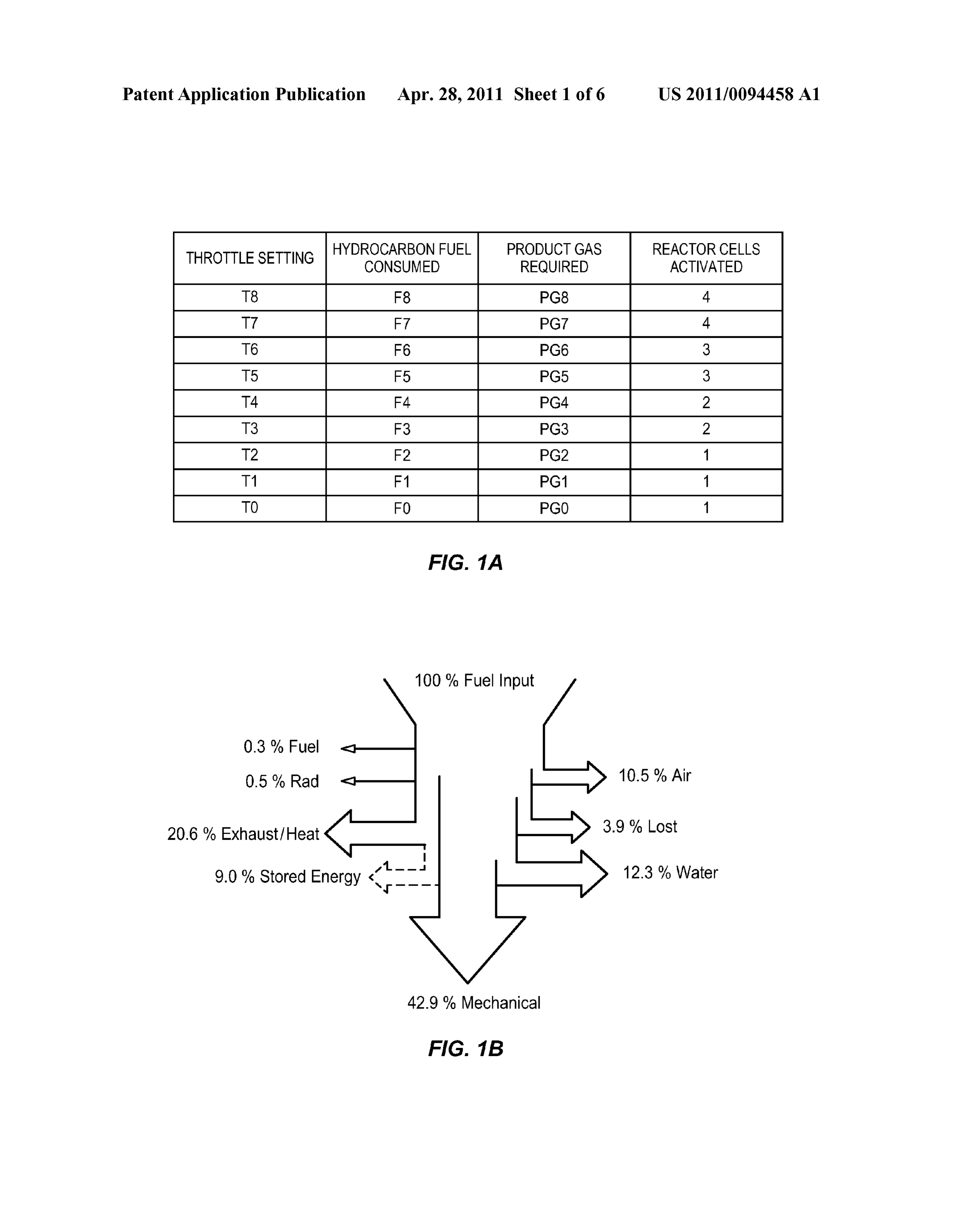
0028. Unlike the HRM, which introduces a competitive BRIEF DESCRIPTION OF THE DRAWINGS reaction into the internal combustion engine, this approach 0033 FIG. 1A illustrates, in tabular form, the operation of directly addresses the primary reaction driving the hydrocar the Combustion Management System; and FIG.1B illustrates bon combustion mechanism toward completion. This a Sankey Diagram of the combustion process controlled by approach creates a twofold increase in the reactive tendency the Combustion Management System; toward completion. Hydroxide radicals (OH) are lighter than 0034 FIG. 2 illustrates, in block diagram form, the typical the standard diatomic oxygen (O) being administered, which elements of one embodiment of the Combustion Manage allows for greater diffusivity and an increased potential for ment System;
oxidative continuance to Supersede polymerization. Also, the 0035 FIG.3 illustrates a typical configuration of the metal higher oxidative potential of the hydroxide radicals (OH) plates contained in the Reactor Cell of the Combustion Man allow for carbon chain cleaving reactions, thus creating more agement System;
reactive sites on the hydrocarbon molecules and greater reac 0036 FIG. 4 illustrates the typical electrical current tion distribution.
0029 Fuel savings are achieved as a result of extracting spread on typical plate geometries in the Reactor Cell of the more stored energy from each hydrocarbon molecule. Every Combustion Management System;
carbon-carbon and carbon-hydrogen bond in the cylinders of 0037 FIG. 5 illustrates a typical gas scrubberfor use in the the internal combustion engine represents stored energy that Combustion Management System; and could be translated into mechanical work. By promoting a 0038 FIG. 6 illustrates, in block diagram form, the Com higher degree of oxidative completion, the Combustion Man bustion Management System as installed with a typical inter agement System extracts more energy from the hydrocarbon nal combustion engine.
fuel. Similarly, emissions of particulate matter, hydrocar DETAILED DESCRIPTION OF THE INVENTION bons, and carbon monoxide from the internal combustion engine are a direct result of this hydrocarbon combustion not Internal Combustion Engines propagating to completion. Therefore, furthering the com bustive process has a direct and measurable impact on both 0039. A diesel engine is an internal combustion engine fuel consumption and emissions reduction. that uses the heat generated by the compression of the atmo 0030. As noted above, polymerization is a problem in spheric air in the combustion chamber to initiate ignition combustive reactions; and the primary causes of polymeriza which burns the diesel fuel, which is injected into the com tion within an engine cylinder are fuel droplet size, turbu bustion chamber during the final stage of compression. This is lence, air composition, molecule size, and reaction mecha in contrast to a gasoline engine, which uses the Otto Cycle, in nism. The Combustion Management System addresses each which an air-fuel mixture, located in the combustion chamber of these dynamics to ensure Successful and consistent reduc and compressed by a piston, is ignited by a spark plug. The tions. The product gas injection port not only administers the gasoline engine has a thermal efficiency (the conversion of
Page 11
US 2011/0094458 A1 Apr. 28, 2011
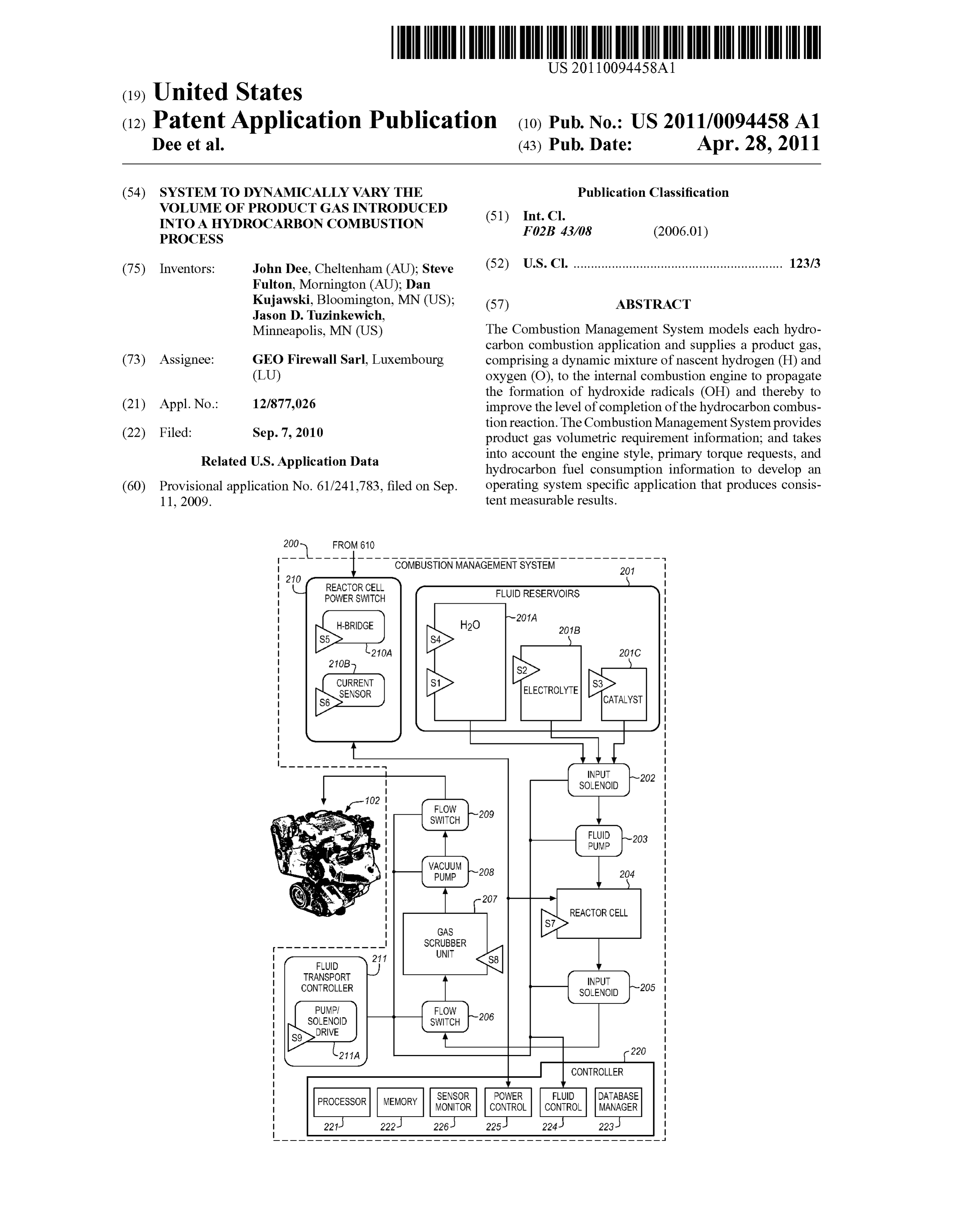
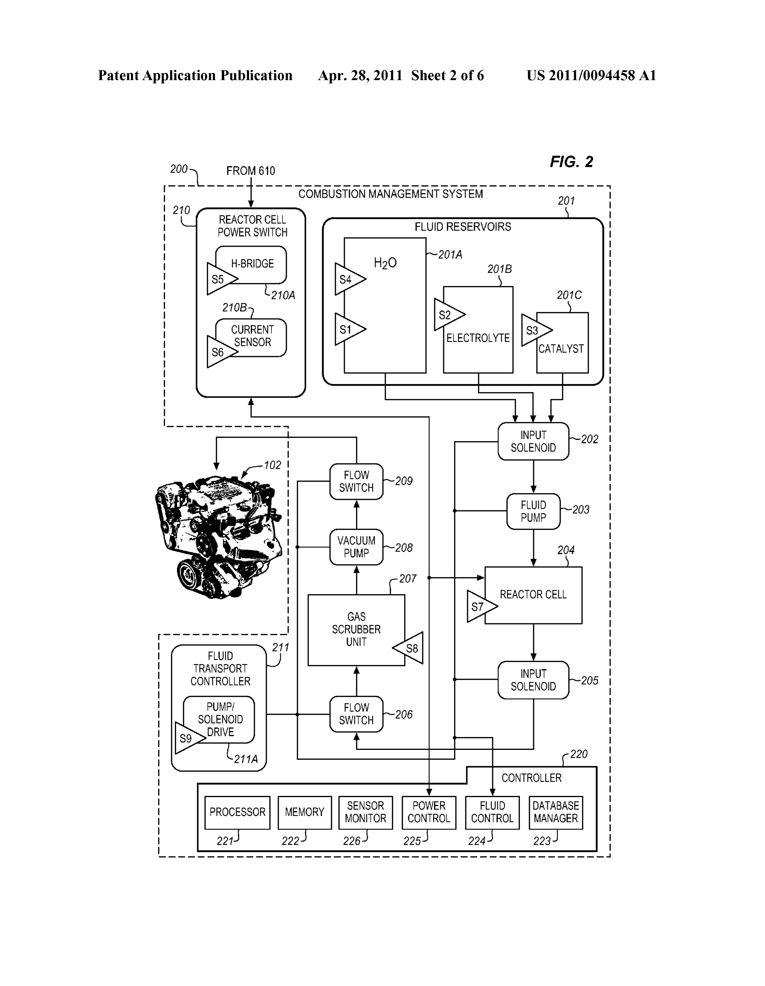
fuel into work) of 8% or 9%, while the diesel engine has a system 604, an atmospheric air intake Supercharger 606, and thermal efficiency of about 30%. an electrical power generator 610. The Combustion Manage 0040. In the diesel engine, only air is initially introduced ment System 200 is powered by electrical energy generated into the combustion chamber. The air then is compressed with by the electric power generator 610 and produces a product a compression ratio typically between 15:1 and 22:1, result gas PG which is mixed with the incoming atmospheric air at ing into a 40-bar (4.0 MPa; 580 psi) pressure compared to 8 to the supercharger 606 and injected into the internal combus 14 bars (0.80 to 1.4 MPa) (about 200 psi) in the gasoline tion engine 602 in well-known fashion. engine. This high compression of the diesel engine heats the air to approximately 550° C. (1,022 F.). At about this Combustion Management System moment, fuel is injected directly into the compressed air in the combustion chamber. This may be into avoid (typically 0044 FIG. 2 illustrates, in block diagram form, the typical toroidal in shape) in the top of the piston or a pre-chamber elements of one embodiment of Combustion Management depending upon the design of the diesel engine. The fuel System 200. A set of fluid reservoirs 201 is provided to store injector ensures that the fuel is broken down into small drop a plurality of fluids, each in a designated one of reservoirs lets and that the fuel is distributed evenly. The heat of the 201A-201C. A first reservoir 201A stores a quantity of water, compressed air vaporizes fuel from the surface of the drop which is used to dissociate monatomic Hydrogen (H) and lets. The vapour then is ignited by the heat from the com monatomic Oxygen (O); a second reservoir 201B is used to pressed air in the combustion chamber, the droplets continue store an electrolyte, which is used in Reactor Cell 204 as to vaporize from their surfaces and burn, getting Smaller, until described below; and a third reservoir 201C is used to store a all of the fuel in the droplets has been burned. The start of catalyst, which is used to enhance the reactions in Reactor vaporization causes a delay period during ignition, i.e., the Cell 204 as described below. Each of the reservoirs 201A characteristic diesel knocking sound as the vapor reaches 201C includes a corresponding fluid level sensor S1-S4, as ignition temperature, and causes an abrupt increase in pres described below, to provide indications of the fluid level in each reservoir 201A-201C.
Sure above the piston. The rapid expansion of combustion gases then drives the piston downward, Supplying power to Controller the engine crankshaft.
0041 As well as the high level of compression which 0045. The Controller 220 includes hardware and software allows combustion to take place without a separate ignition specifically designed to manage the Combustion Manage system, a high compression ratio greatly increases the ment System 200 functionality and safety protocol. Control engine's efficiency. Increasing the compression ratio in a ler 220 includes a Processor 221 which monitors and controls spark-ignition engine where fuel and air are mixed before the major logic components, including the capacity to man entry to the cylinder is limited by the need to prevent damag age the multiple iterations of the Reactor Cell Power Switch ing pre-ignition. Since only air is compressed in a diesel 210. Controller 220 also manages fluid transport, user inter engine, and fuel is not introduced into the cylinder until face, data logging, and real time remote access functions. shortly before top dead centre (TDC), premature detonation is 0046. The development of a workable thermodynamic not an issue and compression ratios are much higher. Advanc model is the first step in the development of a viable product. ing the start of injection (injecting before the piston reaches The next critical consideration is understanding the mechani TDC) results in higher in-cylinder pressure and temperature, cal system into which the product is integrated and identify and higher efficiency, but also results in elevated engine noise ing the key variables pertinent to the Success of the integra and increased oxides of nitrogen (NOx) emissions due to tion. Fuel delivery, sensory control loops, fuel consumption higher combustion temperatures. Delaying the start of injec rates, duty cycle, transient state dynamics, and mean RPMs tion causes incomplete combustion, reduced fuel efficiency, are just a few of the variables to consider when preparing to and an increase in exhaust Smoke, containing a considerable integrate. Presently, the Combustion Management System amount of particulate matter and unburned hydrocarbons. 200 is optimized for low RPM, high-duty-cycle engines. 0042. In addition, diesels develop maximum horsepower Long operating times in steady state conditions and limited and efficiency over a wide range of speeds. Diesel engines feedback loop management systems provide for a simpler typically are also equipped with a turbocharger, which uses interface than the dynamic and stringently managed systems exhaust gases from the diesel engine to drive a turbine that seen in the higher RPM and lower-duty-cycle systems. Supplies highly compressed air to rapidly remove (Scavenge) exhaust gases from the cylinders. This increases the compres 0047 FIG. 1A illustrates, in tabular form, the operation of sion in the cylinders and helps to cool the cylinders and the Combustion Management System 200. The Combustion cylinder heads. The increased compression in the cylinder Management System 200 makes use of a hydrocarbon com results in higher efficiency in burning the fuel, and hence, bustion process model, Stored in memory 222, which deter more horsepower. A turbocharger can increase the power mines the volume of a product gas PG required for a volume output of a diesel engine by 30% to 50%, depending on of hydrocarbon fuel F which is required to improve the level various factors. of completion of the hydrocarbon fuel combustion process. Also provided is a mapping of the number of Reactor Cells
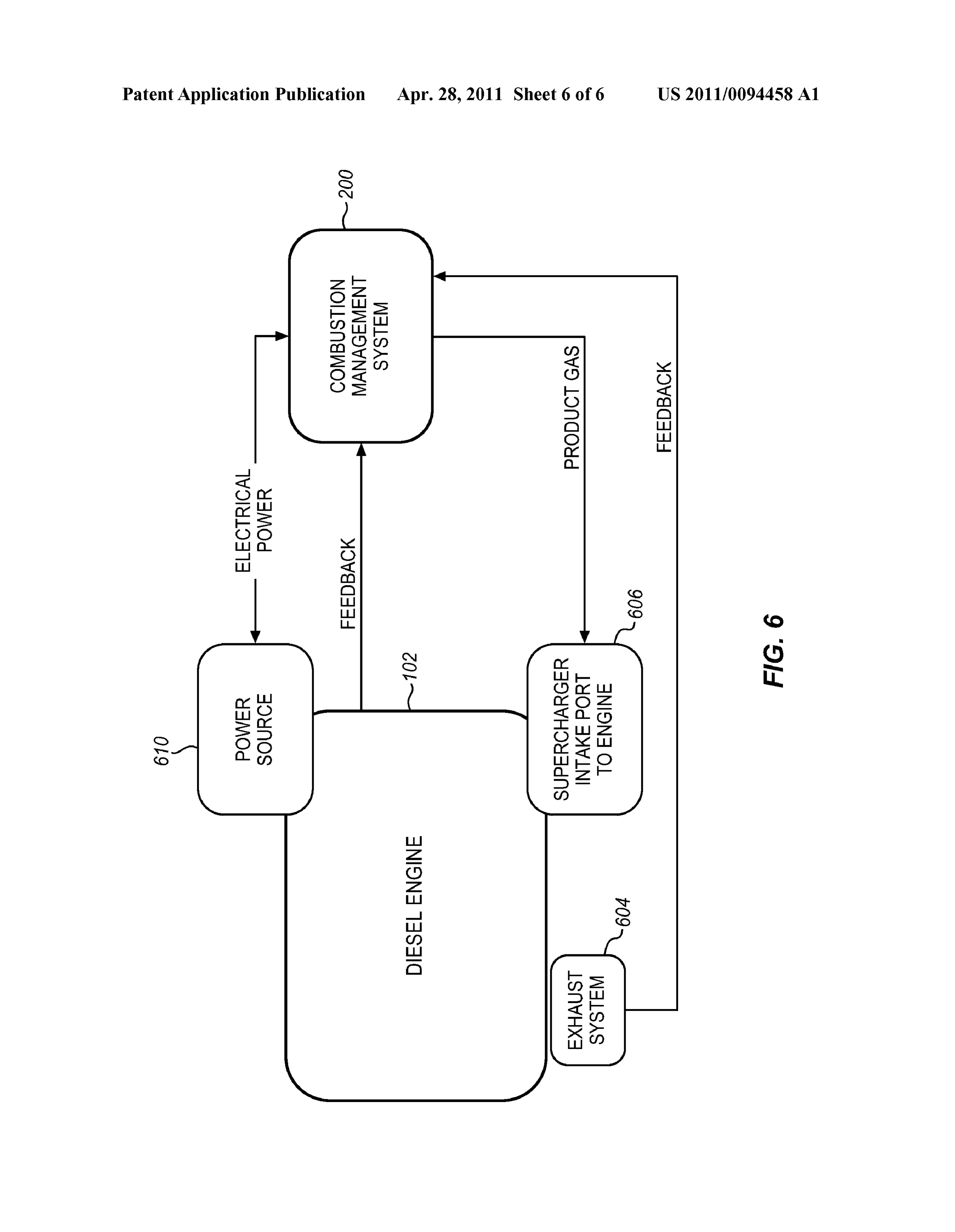
System Application 204 that need to be active in order to provide an adequate amount of the product gas PG, as determined from this chart.
0043 FIG. 6 illustrates, in block diagram form, Combus There is shown a column labelled “Throttle Setting” which is tion Management System 200 as installed in an existing inter one of the simple metrics which can be associated with a nal combustion engine 602, as an example of the use of the volume or range of volumes of hydrocarbon fuel which is Combustion Management System 200 with a hydrocarbon consumed by the hydrocarbon fuel consuming process. There combustion process. The internal combustion engine 602 is are a number of operating characteristics which can be used equipped with standard components consisting of an exhaust for this purpose and they include, but are not limited to:
Page 12
US 2011/0094458 A1 Apr. 28, 2011
engine Revolutions Per Minute, engine turbocharger Revolu S1-S9, the Sensor Monitor 226 of the Controller 220 tions Per Minute, internal diagnostic array of the engine, Surveys the status of each sensor for data logging; exhaust flow of the combustion by-products, engine cylinder 0.055 5. Maintain watchdog circuit: Reactor Cell Power pressure, and the like. Thus, an engine operating characteris Control 225 anticipates communication with Controller tic is indicative of a corresponding hydrocarbon fuel con 220 at regular intervals, and goes into an error mode if Sumption Volume, which can actually be a range of hydrocar communication cannot be confirmed; bon fuel Volumes, since the engine operating characteristic 0056 6. Monitor cell liquid level: A sensor S7 is built may not be a simple immutable number but can consist of a into the structure of the Reactor Cell 204 to monitor the “level of operation. For example, the throttle setting T is fluid at the minimum desired level; the sensor signal is indicative of a demand for power from the engine, but the "de-bounced, meaning that a low level indication must throttle setting can be a continuous variable; and a particular persist for a predetermined time before it is acted upon to throttle setting T3 could be indicative of a request which falls compensate for the effects of normal fluid motions in a between predetermined limits on a range of the continuum of moving application;
throttle settings. 0057 7. Monitor the printed circuit board temperature 0048. The product gas volume also is indicative of a in the vicinity of the H-bridge 210A via temperature required volume of product gas PG for the volume of hydro sensor S6: High temperatures can damage the circuitry; carbon fuel associated with a selected throttle setting (or other and high temperatures are likely an indication of a larger measured engine operating characteristic). The number of functional issue which Suggests the need for further Reactor Cells required to supply this Volume of product gas inspection; and
PG is selected to provide ample reserve to account for 0.058 8. Monitor supply voltage: If supply voltage changes in the demand for product gas PG. begins to drop, the power source 610 is not providing sufficient power to support the operation of the Reactor
Reactor Cell Power Control and Power Switch Cell 204 as well as the internal combustion engine's 0049 Reactor Cell Power Control 225 optimizes the elec operating systems; a drop of 1.5 V or more is an indica trochemical reaction in Reactor Cell 204 within the param tion that the Combustion Management System 200 eters of the Combustion Management System 200. This com needs to shut down until the Combustion Management ponent manages the extremely high current utilized by the System 200 can be inspected. Reactor Cell 204. Current is monitored using current sensor The Controller 220 responds to received fluid level indica 210A, and decisions are made by the Reactor Cell Power tions by activating selected ones of the input solenoids 202 to Control 225 as a function of the present request for current enable fluid flows from reservoirs 201A-201C to Reactor received from Reactor Cell 204. A square wave signal is Cells 204 as provided by associated fluid pumps 203. generated by the Reactor Cell Power Switch 210 at frequen cies which optimize the electrochemical reaction in Reactor Reactor Cells
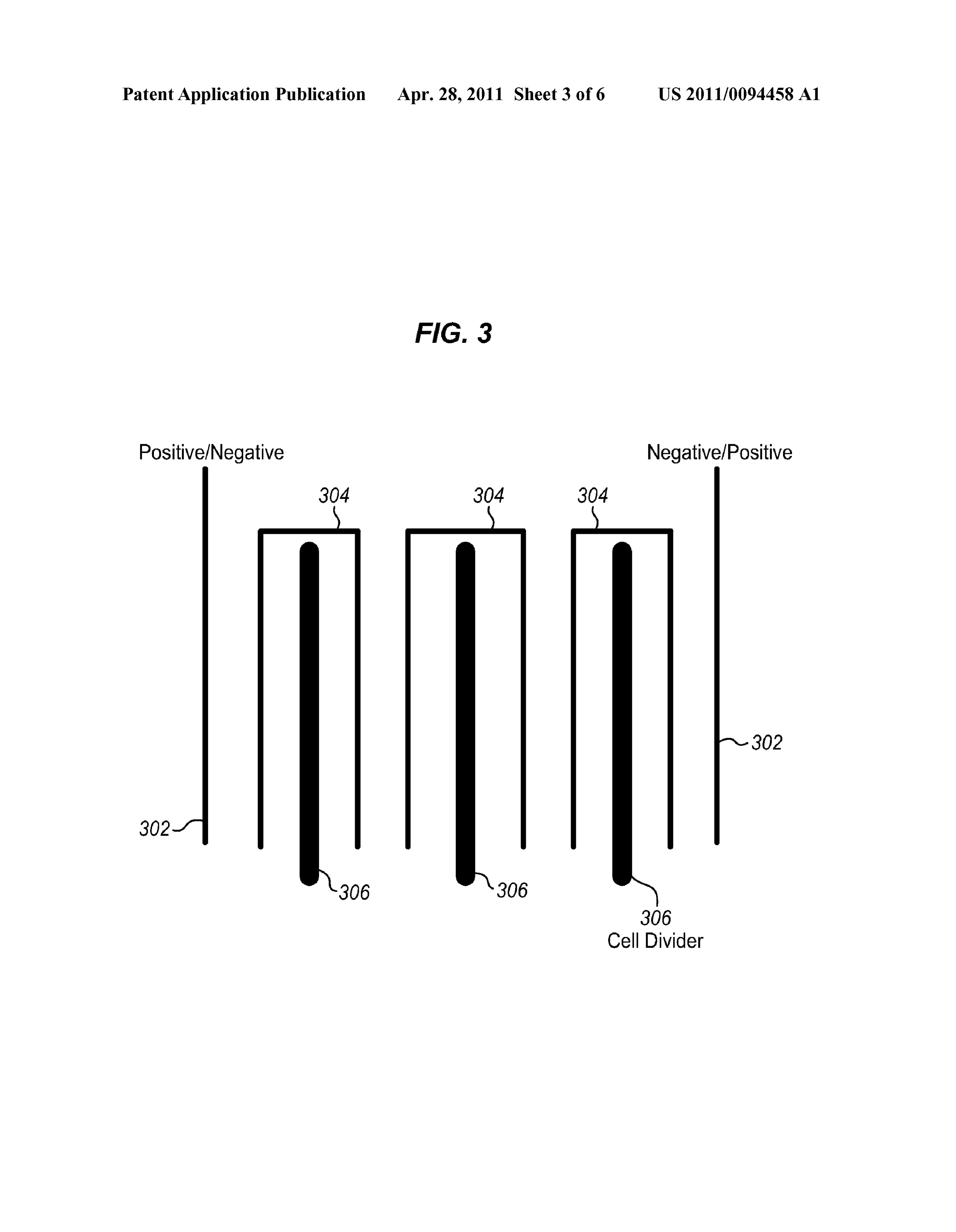
Cell 204, while the duty cycle of the square wave signal is 0059 FIG. 4 illustrates a typical configuration of the metal adjusted to limit the effective current draw with sensitivity to plates contained in the Reactor Cell 204 of the Combustion the capacitive effect of the reaction. An H-bridge 210A, Management System 200. The design utilizes bridged pair which is an electronic circuit which enables a voltage to be plates 404 with insulating partitions dividing each pair 406 applied across a load in either direction, is utilized to reverse and an entry electrode 402. Plate design and configuration are polarity across the terminals of the Reactor Cell 204 with based on a combination of electrochemical standards and regularity to reduce migration, again with special accommo physical electron transport process dynamics. dations for the Reactor Cell's capacitance.
0050. The following is a list of typical logic considerations 0060 FIG. 5 illustrates the typical electrical current performed by the Reactor Cell Power Control 225: spread on typical plate geometries in Reactor Cell 204 of the Combustion Management System 200 and is an example of 0051 1. Measure electric current flowing through the current dispersion optimization based on 30% electron drift electrodes of Reactor Cell 204; (506, 512) along the diagonal (504, 510). The square plate 0.052 2. Communicate pump activation requests to (502) has a great percentage of Surface area that does not Fluid Control Module 224: In the event that sensors achieve enough current to propagate reasonable reaction effi S1-S4 indicate a need for addition of water from reser ciency. By changing the plate dimensions to a 3:1 ratio (508), voir 201A, concentrated electrolyte from reservoir such as 2"x6", the current effective area is a much greater 201B, or catalyst from reservoir 201C, the request is percentage of the Surface area of the plate. Maximizing cur communicated to Fluid Control Module 224 for fluid rent saturation has the following effects: more electrons transport management; propagating reaction, increased reactor efficiency, and lower 0053. 3. Communicate shut-down status of a Reactor heat generation.
Cell 204 to Reactor Cell Power Switch 210: When Reac 0061 Electrochemically, a 1.23 V potential will break the tor Cells 204 are linked in parallel, a failure of one Hydrogen-Oxygenbonding in water. In a twelve-volt system, individual Reactor Cell 204 does not require the entire this corresponds to ten plate pairs in series, with twenty plate Combustion Management System 200 to shut down; pairs for a twenty-four volt System configuration. The plates when Reactor Cells 204 are linked in series, the entire are part of an induced series configuration propagating the series block is deactivated. Any shut-down condition is current through an alternating sequence of straight shorts and communicated to an operator and logged with a master electrolytic media connection. In one implementation of the control database 223 located in Controller 220; Combustion Management System 200, nonconductive divid 0054 4. Respond to requests for information: In the ers are used to ensure proper charge orientation and distribu event that no alerts are generated by the sensor array tion.
Page 13
US 2011/0094458 A1 Apr. 28, 2011
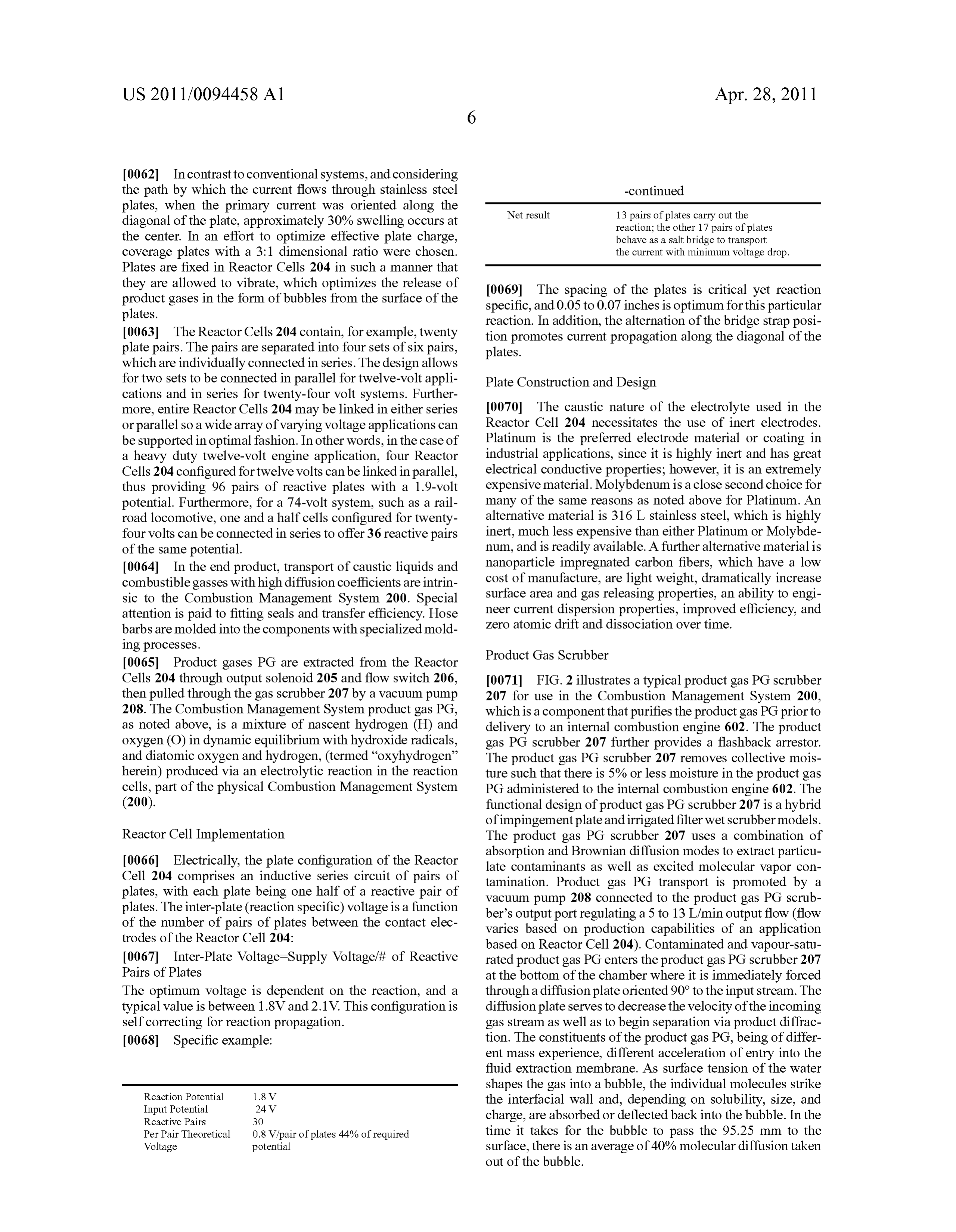
0062. In contrast to conventional systems, and considering the path by which the current flows through stainless steel -continued plates, when the primary current was oriented along the Netresult 13 pairs of plates carry out the diagonal of the plate, approximately 30% Swelling occurs at reaction; the other 17 pairs of plates the center. In an effort to optimize effective plate charge, behave as a salt bridge to transport coverage plates with a 3:1 dimensional ratio were chosen. the current with minimum voltage drop. Plates are fixed in Reactor Cells 204 in such a manner that they are allowed to vibrate, which optimizes the release of 0069. The spacing of the plates is critical yet reaction product gases in the form of bubbles from the surface of the specific, and 0.05 to 0.07 inches is optimum for this particular plates. reaction. In addition, the alternation of the bridge strap posi 0063. The Reactor Cells 204 contain, for example, twenty tion promotes current propagation along the diagonal of the plate pairs. The pairs are separated into four sets of six pairs, plates.
which are individually connected in series. The design allows for two sets to be connected in parallel for twelve-volt appli Plate Construction and Design cations and in series for twenty-four volt systems. Further more, entire Reactor Cells 204 may be linked in either series 0070 The caustic nature of the electrolyte used in the or parallel so a wide array of varying Voltage applications can Reactor Cell 204 necessitates the use of inert electrodes. be supported in optimal fashion. In other words, in the case of Platinum is the preferred electrode material or coating in a heavy duty twelve-volt engine application, four Reactor industrial applications, since it is highly inert and has great Cells 204 configured for twelve volts can be linked in parallel, electrical conductive properties; however, it is an extremely thus providing 96 pairs of reactive plates with a 1.9-volt expensive material. Molybdenum is a close second choice for potential. Furthermore, for a 74-volt system, such as a rail many of the same reasons as noted above for Platinum. An road locomotive, one and a half cells configured for twenty alternative material is 31.6 L stainless steel, which is highly four volts can be connected in series to offer 36 reactive pairs inert, much less expensive than either Platinum or Molybde of the same potential. num, and is readily available. A further alternative material is 0064. In the end product, transport of caustic liquids and nanoparticle impregnated carbon fibers, which have a low combustible gasses with high diffusion coefficients are intrin cost of manufacture, are light weight, dramatically increase sic to the Combustion Management System 200. Special Surface area and gas releasing properties, an ability to engi attention is paid to fitting seals and transfer efficiency. Hose neer current dispersion properties, improved efficiency, and barbs are molded into the components with specialized mold Zero atomic drift and dissociation over time. ing processes.
Product Gas Scrubber 0065 Product gases PG are extracted from the Reactor
Cells 204 through output solenoid 205 and flow switch 206, 0071 FIG. 2 illustrates a typical product gas PG scrubber then pulled through the gas scrubber 207 by a vacuum pump 207 for use in the Combustion Management System 200, 208. The Combustion Management System product gas PG. which is a component that purifies the product gas PG prior to as noted above, is a mixture of nascent hydrogen (H) and delivery to an internal combustion engine 602. The product oxygen (O) in dynamic equilibrium with hydroxide radicals, gas PG scrubber 207 further provides a flashback arrestor. and diatomic oxygen and hydrogen, (termed "oxyhydrogen The product gas PG scrubber 207 removes collective mois herein) produced via an electrolytic reaction in the reaction ture such that there is 5% or less moisture in the product gas cells, part of the physical Combustion Management System PG administered to the internal combustion engine 602. The (200). functional design of product gas PG scrubber 207 is a hybrid of impingement plate and irrigated filter wet scrubber models.
Reactor Cell Implementation The product gas PG scrubber 207 uses a combination of 0066 Electrically, the plate configuration of the Reactor absorption and Brownian diffusion modes to extract particu Cell 204 comprises an inductive series circuit of pairs of late contaminants as well as excited molecular vapor con plates, with each plate being one half of a reactive pair of tamination. Product gas PG transport is promoted by a plates. The inter-plate (reaction specific) Voltage is a function vacuum pump 208 connected to the product gas PG scrub ber's output port regulating a 5 to 13 L/min output flow (flow of the number of pairs of plates between the contact elec varies based on production capabilities of an application trodes of the Reactor Cell 204:
based on Reactor Cell 204). Contaminated and vapour-satu 0067 Inter-Plate Voltage=Supply Voltage/it of Reactive rated product gas PG enters the product gas PG scrubber 207 Pairs of Plates at the bottom of the chamber where it is immediately forced The optimum Voltage is dependent on the reaction, and a through a diffusion plate oriented 90° to the input stream. The typical value is between 1.8V and 2.1V. This configuration is diffusion plate serves to decrease the velocity of the incoming self correcting for reaction propagation. gas stream as well as to begin separation via product diffrac 0068 Specific example: tion. The constituents of the product gas PG, being of differ ent mass experience, different acceleration of entry into the fluid extraction membrane. As surface tension of the water
Reaction Potential 1.8V shapes the gas into a bubble, the individual molecules strike
Input Potential 24 V.
the interfacial wall and, depending on Solubility, size, and
Reactive Pairs 30 charge, are absorbed or deflected back into the bubble. In the Per Pair Theoretical 0.8 V pair of plates 44% of required time it takes for the bubble to pass the 95.25 mm to the Voltage potential surface, there is an average of 40% molecular diffusion taken out of the bubble.
Page 14
US 2011/0094458 A1 Apr. 28, 2011
0072. The product gas PG scrubber 207 is a reservoir 0.076 Negative air pressure at injection; comprised of one input port and two output ports, a level 0.077 Homogenous mixing:
sensor, and four gas diffusion plates. A vacuum pump is 0078. Fuel injection timing recalibration; connected to the output port at the top of the reservoir. The 0079. In common rail, achievement of surplus hydrogen Reactor Cell product gas PG output ports are connected to the for all torque requests; and input port at the base of the reservoir. The reservoir contains 0080 Interface with CAN Bus in newer engine types. an electrolyte fluid, which acts as a filter and a separator. Fuel Interface
Product gasses are forced via the vacuum produced by the pump through the primary diffusion plate, traveling through I0081. The fuel interface method mixes the product gases the fluid in the form of small bubbles. Surface area and bubble PG directly into the combustive fuel prior to injection. In one size are a primary consideration because this media separa implementation, the system utilizes a venturi effect mixing tion allows the system to collect/scavenge impurities for apparatus to dissolve the product gas PG components into the diesel fuel in the line. Due to the low solubility of oxygen, the return to the liquid medium. The three diffusion plates at the un-dissolved gas is extracted using a fluid/gas extractor com top of the reservoir have offset porting and act as a conden ponent installed pre-fuel filter. The extracted gas is adminis sation matrix. During operation, the liquid level in the reser tered to the air Supply using the air interface component. Fuel voir will rise, which is monitored by the level switch. The interface technology is novel as compared to the Hydrogen secondary output port is attached to a liquid pump which Enhanced Combustion state of the art. To ensure repeatable extracts excess liquid and returns it to the reaction Supply. The Success of this method, the following considerations are product gas PG scrubber fluid is the same as the electrolyte in achieved:
the cells. 0082 Hydrogen is thoroughly dissolved in fuel This is achieved via a stationary mixing tube, the application
Fluid Transport System specific design which is laboratory proven for maximum 0073. The fluid transport system is responsible for main threshold values prior to installation; taining proper electrolyte levels in the Reactor Cells 204 as 0.083. Any un-dissolved gas is extracted prior to enter ing common rail—A special gas phase separator is well as ensuring proper extraction and delivery of product added to the fuel line before the common rail or injector gases PG. A liquid pump and Solenoid valve manifold trans housing:
port water, concentrated electrolyte, and catalyst to desig 0084 Stable at high temperatures and pressures: nated compartments. A system of level sensors and control 0085) Hydrogen is free upon injection; logic directs operations, as well as monitors functioning of I0086) 5% molar hydrogen to fuel—A dosing pump is components. calibrated to application-specific fuel line requirements; 0074 All liquid media is filled and stored in one or more 0.087 Extracted gas (un-dissolved oxygen) is injected reservoirs—unique to each particular application. For into the air supply; and example, a short haul operating system where the truck 0088 Recirculated fuel is stable (no buildup of hydro returns to a base at the end of every day generally can function gen in fuel tank).
on a five-gallon water tank that can be topped off at the Electrolyte Chemistry beginning of each day, whereas a locomotive engine that runs for many days at a time without reaching a servicing base will I0089. The chemical composition of the electrolyte deter likely require a much larger water reservoir. Storage levels are mines the rate, efficiency, and product of the electrolysis. set according to the duty cycle of the engine the unit to which KOH is the electrolytic catalyst of choice in the Hydrogen it is attached. In one implementation, filling is a “no touch” Enhanced Combustion (HEC) market, although concentra pump driven operation. For instance, the reservoir may be tions vary from company to company. The Combustion Man connected to the Solenoid manifold and liquid pump. The agement System technology utilizes a 1.5% molar concentra manifold is connected to other components of the system to tion of KOH, which is a strong Base (alkaline). Theoretically, manage fluid flow between the components. Level sensors in any alkaline can serve the primary function, but other char each component work with the manifold and pump to main acteristics of the alkaline elements make them unfavorable as tain proper levels in each unit during operation. In one imple catalysts in this environment. The reaction equation is multi mentation, the process control logic contains de-bouncing functional. KOH dissociates in water to form K+OH. algorithms, event timers, alerts, and corresponding eventhan These components, being catalytic, have no place in the dlers (e.g., to provide information regarding proper function actual half reactions. Combustion Management System 108 ing of the liquid system, to automatically shut down in the also utilizes the wetting properties of a non-foaming Surfac event of a failure or procedural anomaly, etc.) and/or so on. A tant as a process catalyst in specialized applications. Surfac basic de-bouncing algorithm will require the reed Switch to tant catalysis provides energetic favorability and promotion trigger for a full 5 seconds to insure that the trigger event of a hydrogen specific product gas. wasn't a product of an instantaneous event such as bouncing 0090 HEC technology utilizes catalysis as a promoter of or sloshing. electrochemical efficiency and increased product gas PG pro duction by reducing the enthalpy of decomposition. Proper
Air Interface electrolyte chemistry promotes current transfer between elec trodes. A good electrolytic catalyst also facilitates extraction 0075 Produced gas mixes into compressed air of the turbo of product gas PG atoms from the reactive electrode. line. The delivery system is a venturi effect inducer port installed directly into the turbo line of the engine system. In Overview Regarding Hydrogen Enhanced Combustion Gains order to achieve consistent Success, the following consider 0091. The administration of a hydrogen/oxygen gas mix ations are characterized for each engine type: ture fundamentally improves the overall combustion reaction
Page 15
US 2011/0094458 A1 Apr. 28, 2011
efficiency by driving the reaction to a higher level of comple carbon as a direct measure of the percentage to which the tion. This improvement translates into a significant increase combustion reaction has been propagated to its completion. in energy released and decreased fuel requirement.
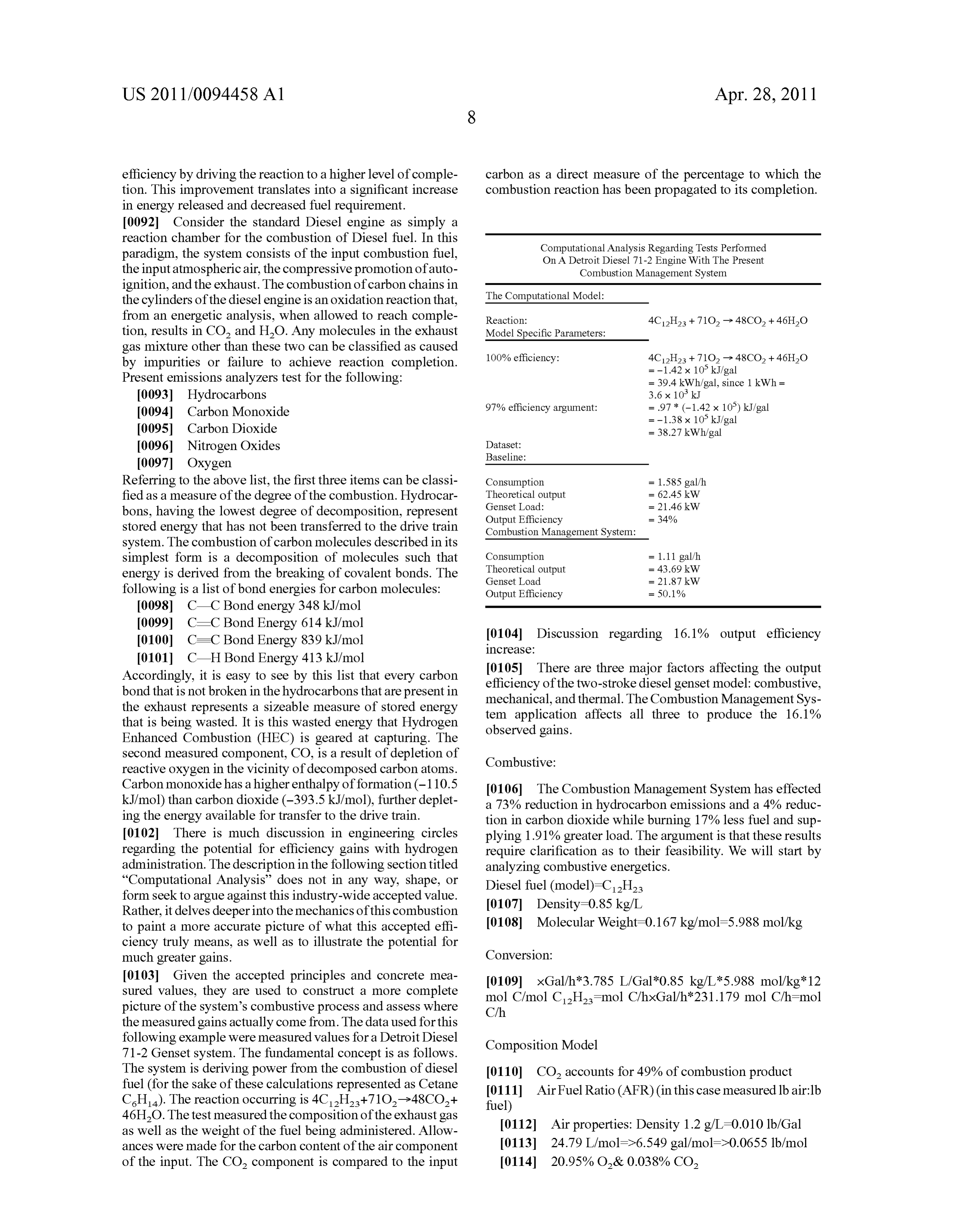
0092 Consider the standard Diesel engine as simply a reaction chamber for the combustion of Diesel fuel. In this paradigm, the system consists of the input combustion fuel, Computational Analysis Regarding Tests Performed On A Detroit Diesel 71-2 Engine With The Present the input atmospheric air, the compressive promotion of auto Combustion Management System ignition, and the exhaust. The combustion of carbon chains in The Computational Model:
the cylinders of the diesel engine is an oxidation reaction that, from an energetic analysis, when allowed to reach comple Reaction:
tion, results in CO and H2O. Any molecules in the exhaust Model Specific Parameters:
gas mixture other than these two can be classified as caused 100% efficiency: 4C2H2 + 71O -> 48CO2 + 46H2O by impurities or failure to achieve reaction completion. = -1.42 x 10 kJ/gal Present emissions analyzers test for the following: = 39.4kWh/gal, since 1 kWh = (0093. Hydrocarbons 3.6 x 10 kJ 0094 Carbon Monoxide 97% efficiency argument: = .97 * (-1.42 x 10) kJ/gal
0095 Carbon Dioxide = 38.27 kWh/gal (0096) Nitrogen Oxides Dataset:
Baseline:
Referring to the above list, the first three items can be classi Consumption = 1.585 gal/h fied as a measure of the degree of the combustion. Hydrocar Theoretical output
Genset Load:
bons, having the lowest degree of decomposition, represent Output Efficiency = 34% stored energy that has not been transferred to the drive train Combustion Management System:
system. The combustion of carbon molecules described in its simplest form is a decomposition of molecules such that Consumption = 1.11 galh energy is derived from the breaking of covalent bonds. The Theoretical output = 43.69 kW
following is a list of bond energies for carbon molecules: Output Efficiency = 50.1% (0098 C C Bond energy 348 kJ/mol (0099 C–C Bond Energy 614 kJ/mol 0100 C=C Bond Energy 839 kJ/mol 0104 Discussion regarding 16.1% output efficiency increase:
0101 C H Bond Energy 413 kJ/mol 0105. There are three major factors affecting the output Accordingly, it is easy to see by this list that every carbon efficiency of the two-stroke diesel genset model: combustive, bond that is not broken in the hydrocarbons that are present in mechanical, and thermal. The Combustion Management Sys the exhaust represents a sizeable measure of stored energy tem application affects all three to produce the 16.1% that is being wasted. It is this wasted energy that Hydrogen observed gains.
Enhanced Combustion (HEC) is geared at capturing. The second measured component, CO, is a result of depletion of Combustive:
reactive oxygen in the vicinity of decomposed carbon atoms.
Carbon monoxide has a higher enthalpy of formation (-110.5 0106 The Combustion Management System has effected kJ/mol) than carbon dioxide (-393.5 kJ/mol), further deplet a 73% reduction in hydrocarbon emissions and a 4% reduc ing the energy available for transfer to the drive train. tion in carbon dioxide while burning 17% less fuel and Sup 0102 There is much discussion in engineering circles plying 1.91% greater load. The argument is that these results regarding the potential for efficiency gains with hydrogen require clarification as to their feasibility. We will start by administration. The description in the following section titled analyzing combustive energetics. “Computational Analysis” does not in any way, shape, or Diesel fuel (model)-CH form seek to argue against this industry-wide accepted value. 0107 Density=0.85 kg/L
Rather, it delves deeper into the mechanics of this combustion to paint a more accurate picture of what this accepted effi (0.108 Molecular Weight=0.167 kg/mol=5.988 mol/kg ciency truly means, as well as to illustrate the potential for much greater gains. Conversion:
0103) Given the accepted principles and concrete mea 0109 xGal/h3.785 L/Gal*0.85 kg/L*5.988 mol/kg 12 Sured values, they are used to construct a more complete mol C/mol CH mol C/hxGal/h 231.179 mol C/h-mol picture of the system's combustive process and assess where C/h the measured gains actually come from. The data used for this following example were measured values for a Detroit Diesel Composition Model 71-2 Genset system. The fundamental concept is as follows.
The system is deriving power from the combustion of diesel 0110 CO accounts for 49% of combustion product fuel (for the sake of these calculations represented as Cetane 0111 Air Fuel Ratio (AFR) (in this case measured lb air:lb CH). The reaction occurring is 4CH+710->48CO+ fuel) 46H2O. The test measured the composition of the exhaust gas 0112 Air properties: Density 1.2 g/L=0.010 lb/Gal as well as the weight of the fuel being administered. Allow ances were made for the carbon content of the air component 0113 24.79 L/mol=>6.549 gal/mol=>0.0655 lb/mol of the input. The CO component is compared to the input 0114 20.95% O& 0.038% CO,
Page 16
US 2011/0094458 A1 Apr. 28, 2011
Baseline: 51.16 lb air/lb fuel 11.9 lb fuel/hr=608.84 lb airf in all forms other than CO coming out of the system. This hr=> number gives an overall conversion efficiency for the com 0115 92.95.27 mol air--1947 mol O+4 mol CO, bustion.
Combustion Management System: 52.7 lb air/lb fuel 9.9 lb fuel/hr=521.73 lb airfhr=> Unavoidable Assumptions:
0116. 7965.34 mol air--1669 mol O+3 mol CO, I0128. The following is a list of assumptions which are 0117 Conservation of mass states that total mass in must deemed unavoidable due to the level of complexity and incon equal total mass out sistency in the specific composition of diesel fuel and atmo spheric air:
I0129. Assumed composition of diesel fuel: CH 0.130 Assumed CO component in atmospheric air:
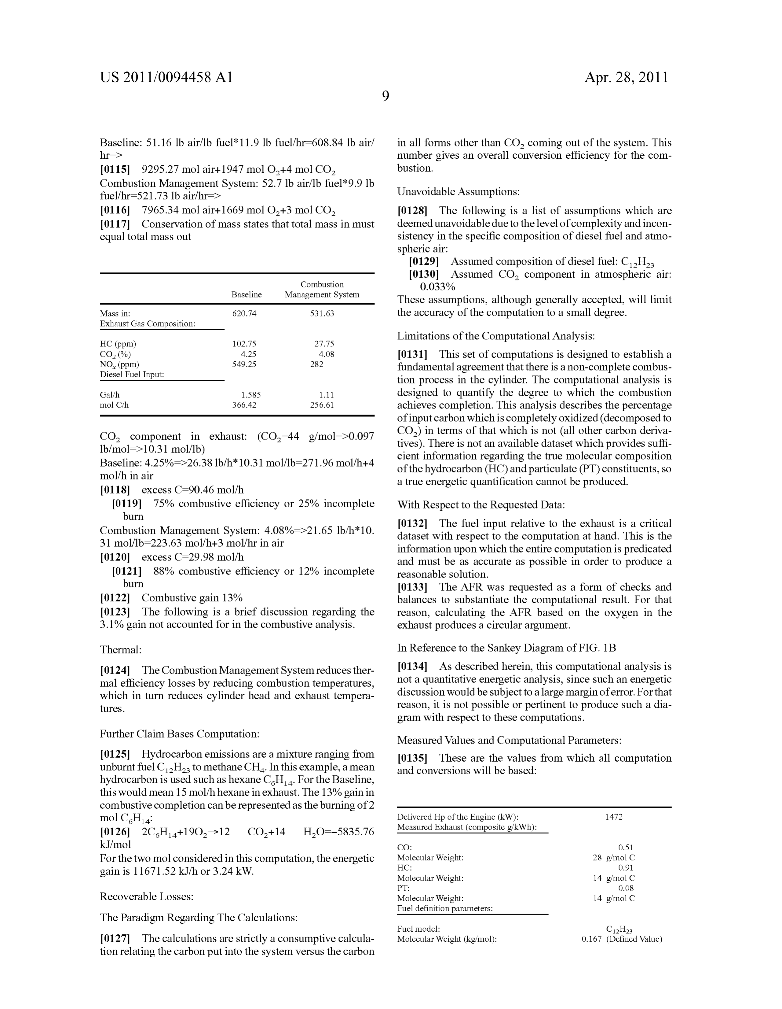
Baseline Management System
These assumptions, although generally accepted, will limit
Mass in: 620.74 531.63 the accuracy of the computation to a small degree. Exhaust Gas Composition:
Limitations of the Computational Analysis:
CO, (%) 4.25 4.08 I0131 This set of computations is designed to establish a NO, (ppm) 549.25 282 fundamental agreement that there is a non-complete combus Diesel Fuel Input: tion process in the cylinder. The computational analysis is Galih 1.585 1.11 designed to quantify the degree to which the combustion mol Ch 366.42 256.61 achieves completion. This analysis describes the percentage of input carbon which is completely oxidized (decomposed to
CO component in exhaust: (CO=44 g/mol=>0.097 CO) in terms of that which is not (all other carbon deriva 1b/mol=>10.31 mol/lb) tives). There is not an available dataset which provides suffi Baseline: 4.25%=>26.38 lb/h 10.31 mol/lb-271.96 mol/h--4 cient information regarding the true molecular composition mol/h in air of the hydrocarbon (HC) and particulate (PT) constituents, so a true energetic quantification cannot be produced.
0119 75% combustive efficiency or 25% incomplete With Respect to the Requested Data:
burn
Combustion Management System: 4.08%->21.65 lb/h10. 0.132. The fuel input relative to the exhaust is a critical 31 mol/lb-223.63 mol/h--3 mol/hr in air dataset with respect to the computation at hand. This is the information upon which the entire computation is predicated 0120 excess C=29.98 mol/h and must be as accurate as possible in order to produce a I0121 88% combustive efficiency or 12% incomplete reasonable solution.
burn I0133. The AFR was requested as a form of checks and 0122 Combustive gain 13% balances to substantiate the computational result. For that 0123. The following is a brief discussion regarding the reason, calculating the AFR based on the oxygen in the 3.1% gain not accounted for in the combustive analysis. exhaust produces a circular argument. Thermal: In Reference to the Sankey Diagram of FIG. 1B 0.124. The Combustion Management System reduces ther I0134. As described herein, this computational analysis is mal efficiency losses by reducing combustion temperatures, not a quantitative energetic analysis, since Such an energetic which in turn reduces cylinder head and exhaust tempera discussion would be subject to a large margin of error. For that tures. reason, it is not possible or pertinent to produce Such a dia gram with respect to these computations.
Further Claim Bases Computation: Measured Values and Computational Parameters: 0.125 Hydrocarbon emissions are a mixture ranging from 0.135 These are the values from which all computation unburnt fuel CH2 to methane CH. In this example, a mean and conversions will be based:
hydrocarbon is used such as hexane C.H. For the Baseline, this would mean 15 mol/h hexane in exhaust. The 13% gain in combustive completion can be represented as the burning of 2 mol CH: Delivered Hp of the Engine (kW): 1472 Measured Exhaust (composite g/kWh):
kJ/mol CO: O.S1 For the two mol considered in this computation, the energetic Molecular Weight:
gain is 11671.52 kJ/h or 3.24 kW. Molecular Weight: 14 g/mol C
Recoverable Losses: Molecular Weight: 14 g/mol C Fuel definition parameters:
The Paradigm Regarding The Calculations:
0127. The calculations are strictly a consumptive calcula Molecular Weight (kg/mol): 0.167 (Defined Value) tion relating the carbon put into the system versus the carbon
Page 17
US 2011/0094458 A1 Apr. 28, 2011
-continued -continued
Fuel Density (kg/L): 0.85 (Defined Value) Carbon atoms administered to the -e 21% Heat of Combustion (MJ/kg): 44.86 (Measured) system in the form of diesel fuel Fuel Input (g/kWh): 203.3 (From ABC) exhausted in a form other than CH Heat of Combustion (kJ/mol): 802.34 (Defined Value) that of CO2, thus taking potential CO vs. COFormation Energy (kJ/mol): 283 (Defined Value) energy with it: 100% - 74%
Conversion parameters:
O.2778 kWh. -> 1 MJ
Energetic Model And Computation:
0.138. The non-CO carbon constituents of diesel engine exhaust are a mixture of literally hundreds of different
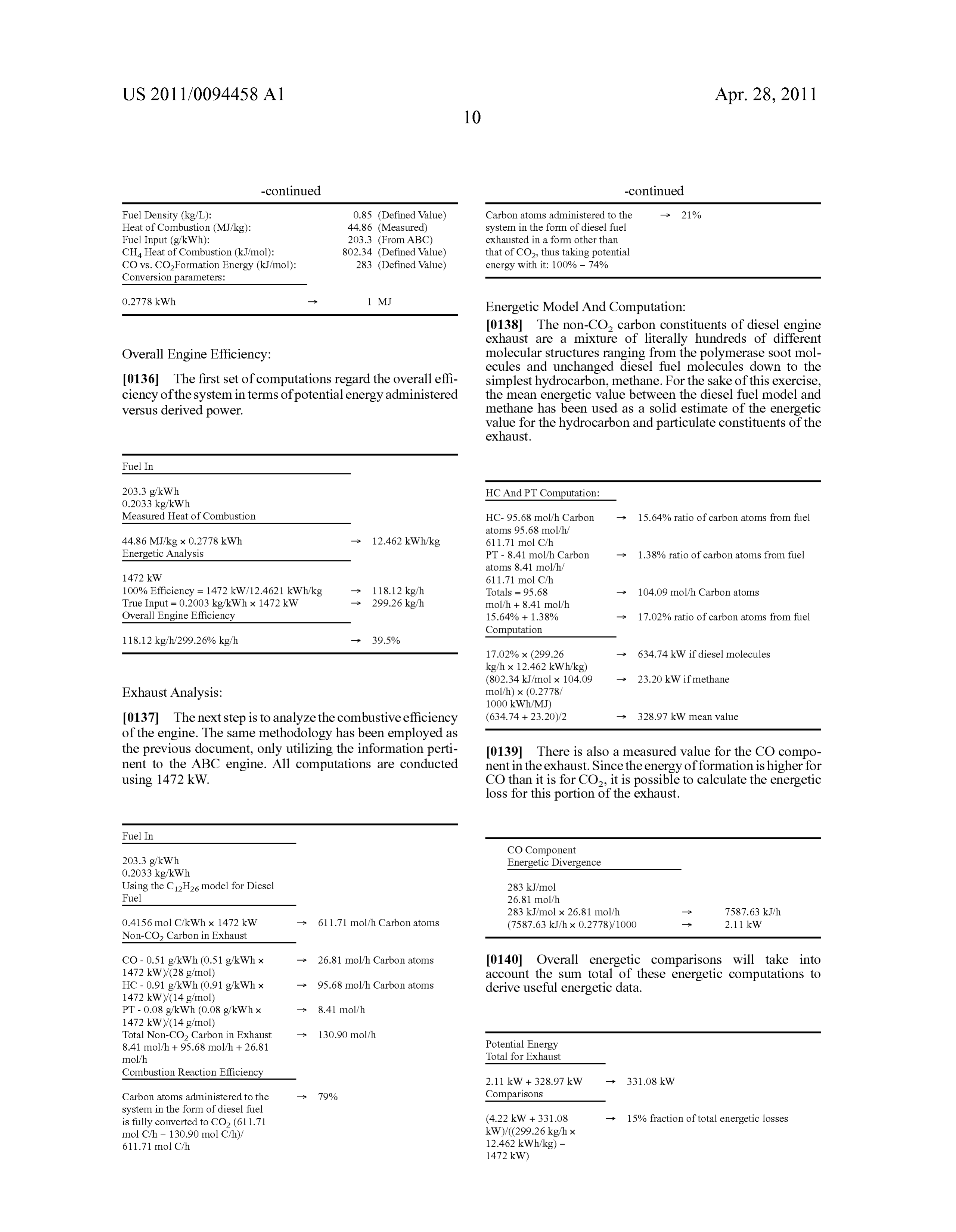
Overall Engine Efficiency: molecular structures ranging from the polymerase soot mol ecules and unchanged diesel fuel molecules down to the 0136. The first set of computations regard the overall effi simplest hydrocarbon, methane. For the sake of this exercise, ciency of the system in terms of potential energy administered the mean energetic value between the diesel fuel model and versus derived power. methane has been used as a Solid estimate of the energetic value for the hydrocarbon and particulate constituents of the exhaust.
Fuel In
203.3 g/kWh. HC And PT Computation:
Measured Heat of Combustion HC-95.68 molh Carbon -> 15.64% ratio of carbon atoms from fuel atoms 95.68 molfh 44.86 MJ/kg x 0.2778 kWh. -> 12.462 kWh/kg 611.71 mol Ch
Energetic Analysis PT - 8.41 molh Carbon -> 1.38% ratio of carbon atoms from fuel atoms 8.41 molfh 1472 kW 611.71 mol Ch 100% Efficiency = 1472 kW/12.4621 kWh/kg -> 118.12 kg/h Totals = 95.68 -> 104.09 molh Carbon atoms True Input = 0.2003 kg/kWh x 1472 kW -> 299.26 kg/h mol/h + 8.41 mol/h
Overall Engine Efficiency 15.64% - 1.38% -> 17.02% ratio of carbon atoms from fuel Computation 118.12 kg/h/299.26% kg/h -e 39.5% 17.02% x (299.26 -> 634.74 kW if diesel molecules
Exhaust Analysis: mol/h) x (0.2778/
0.137 The next step is to analyze the combustive efficiency (634.74 + 23.20)/2 -> 328.97 kW mean value of the engine. The same methodology has been employed as the previous document, only utilizing the information perti 0.139. There is also a measured value for the CO compo nent to the ABC engine. All computations are conducted nent in the exhaust. Since the energy of formation is higher for using 1472 kW. CO than it is for CO, it is possible to calculate the energetic loss for this portion of the exhaust.
Fuel In
CO Component 203.3 g/kWh. Energetic Divergence
Using the C12H2 model for Diesel 283 kJ/mol
Fuel 26.81 mol/h 283 kJ/mol x 26.81 molfh 7587.63 kJ 0.4156 mol C, kWh x 1472 kW -> 611.71 mol/h Carbon atoms (7587.63 kJ/h x 0.2778)/1000 2.11 kW Non-CO2 Carbon in Exhaust
CO - 0.51 g/kWh (0.51 g/kWh x -> 26.81 molh Carbon atoms 0140. Overall energetic comparisons will take into
HC - 0.91 g/kWh (0.91 g/kWh x -> 95.68 molh Carbon atoms account the Sum total of these energetic computations to
derive useful energetic data.
Total Non-CO2 Carbon in Exhaust -> 130.90 molfh 8.41 mol/h + 95.68 molh + 26.81 Potential Energy molfh Total for Exhaust
Combustion Reaction Efficiency
Carbon atoms administered to the -e 79% Comparisons system in the form of diesel fuel is fully converted to CO2 (611.71 (4.22 kW + 331.08 -> 15% fraction of total energetic losses mol C/h - 130.90 mol C/h)/ kW)/((299.26 kg/h x 611.71 mol Ch 12.462 kWh/kg) -
Page 18
US 2011/0094458 A1 Apr. 28, 2011
operating characteristics including, but not limited to:
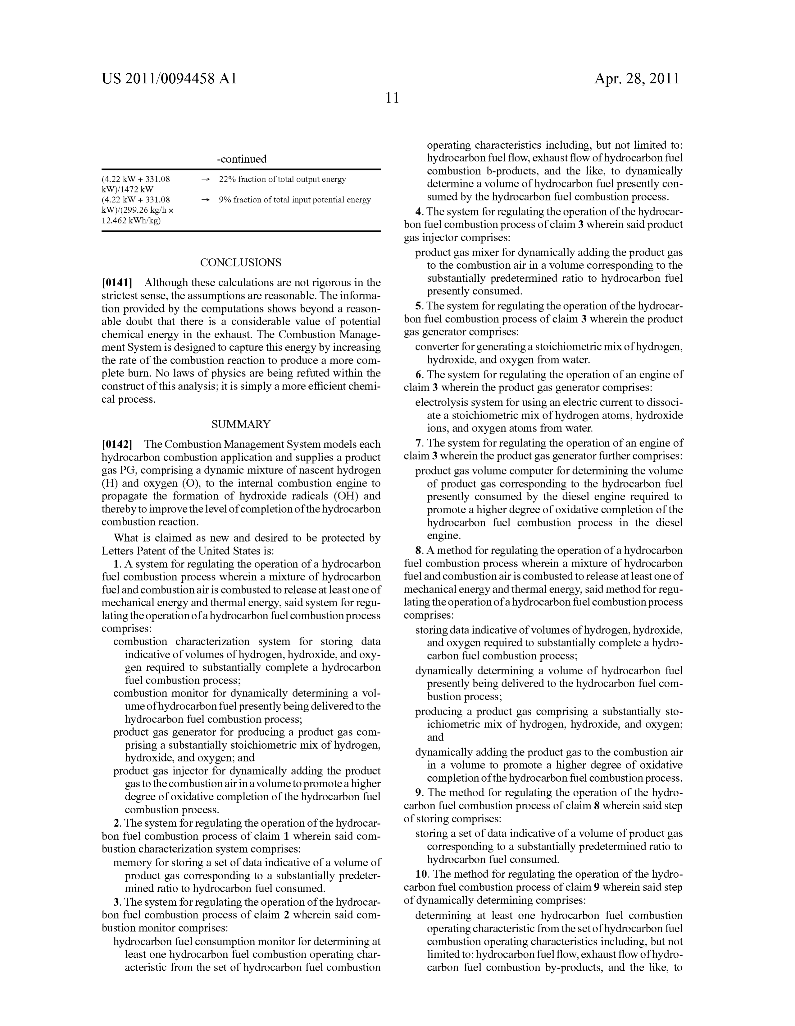
-continued hydrocarbon fuel flow, exhaust flow of hydrocarbon fuel -> 22% fraction of total output energy combustion b-products, and the like, to dynamically (4.22 kW + 331.08 determine a volume of hydrocarbon fuel presently con
(4.22 kW + 331.08 -> 9% fraction of total input potential energy sumed by the hydrocarbon fuel combustion process. kW)/(299.26 kg/h x 4. The system for regulating the operation of the hydrocar 12.462 kWh/kg) bon fuel combustion process of claim 3 wherein said product gas injector comprises:
product gas mixer for dynamically adding the product gas
CONCLUSIONS to the combustion air in a Volume corresponding to the 0141 Although these calculations are not rigorous in the substantially predetermined ratio to hydrocarbon fuel strictest sense, the assumptions are reasonable. The informa presently consumed.
tion provided by the computations shows beyond a reason 5. The system for regulating the operation of the hydrocar able doubt that there is a considerable value of potential bon fuel combustion process of claim 3 wherein the product chemical energy in the exhaust. The Combustion Manage gas generator comprises:
ment System is designed to capture this energy by increasing converter for generating a stoichiometric mix of hydrogen, the rate of the combustion reaction to produce a more com hydroxide, and oxygen from water. plete burn. No laws of physics are being refuted within the 6. The system for regulating the operation of an engine of construct of this analysis; it is simply a more efficient chemi claim 3 wherein the product gas generator comprises: cal process. electrolysis system for using an electric current to dissoci
SUMMARY
ate a stoichiometric mix of hydrogen atoms, hydroxide ions, and oxygen atoms from water.
0142. The Combustion Management System models each 7. The system for regulating the operation of an engine of hydrocarbon combustion application and Supplies a product claim 3 wherein the product gas generator further comprises: gas PG, comprising a dynamic mixture of nascent hydrogen product gas Volume computer for determining the Volume (H) and oxygen (O), to the internal combustion engine to of product gas corresponding to the hydrocarbon fuel propagate the formation of hydroxide radicals (OH) and presently consumed by the diesel engine required to thereby to improve the level of completion of the hydrocarbon promote a higher degree of oxidative completion of the combustion reaction. hydrocarbon fuel combustion process in the diesel What is claimed as new and desired to be protected by engine.
Letters Patent of the United States is: 8. A method for regulating the operation of a hydrocarbon 1. A system for regulating the operation of a hydrocarbon fuel combustion process wherein a mixture of hydrocarbon fuel combustion process wherein a mixture of hydrocarbon fuel and combustion air is combusted to release at least one of fuel and combustion air is combusted to release at least one of mechanical energy and thermal energy, said method for regu mechanical energy and thermal energy, said system for regu lating the operation of a hydrocarbon fuel combustion process lating the operation of a hydrocarbon fuel combustion process comprises:
comprises: storing data indicative of Volumes of hydrogen, hydroxide, combustion characterization system for storing data and oxygen required to Substantially complete a hydro indicative of Volumes of hydrogen, hydroxide, and oxy carbon fuel combustion process;
gen required to Substantially complete a hydrocarbon dynamically determining a Volume of hydrocarbon fuel fuel combustion process; presently being delivered to the hydrocarbon fuel com combustion monitor for dynamically determining a Vol bustion process;
ume of hydrocarbon fuel presently being delivered to the producing a product gas comprising a Substantially sto hydrocarbon fuel combustion process; ichiometric mix of hydrogen, hydroxide, and oxygen; product gas generator for producing a product gas com and prising a Substantially stoichiometric mix of hydrogen, dynamically adding the product gas to the combustion air hydroxide, and oxygen; and in a Volume to promote a higher degree of oxidative product gas injector for dynamically adding the product completion of the hydrocarbon fuel combustion process. gas to the combustionairina Volume to promote a higher degree of oxidative completion of the hydrocarbon fuel 9. The method for regulating the operation of the hydro combustion process. carbon fuel combustion process of claim 8 wherein said step 2. The system for regulating the operation of the hydrocar of storing comprises:
bon fuel combustion process of claim 1 wherein said com storing a set of data indicative of a Volume of product gas bustion characterization system comprises: corresponding to a Substantially predetermined ratio to memory for storing a set of data indicative of a Volume of hydrocarbon fuel consumed.
product gas corresponding to a Substantially predeter 10. The method for regulating the operation of the hydro mined ratio to hydrocarbon fuel consumed. carbon fuel combustion process of claim 9 wherein said step 3. The system for regulating the operation of the hydrocar of dynamically determining comprises: bon fuel combustion process of claim 2 wherein said com determining at least one hydrocarbon fuel combustion bustion monitor comprises: operating characteristic from the set of hydrocarbon fuel hydrocarbon fuel consumption monitor for determining at combustion operating characteristics including, but not least one hydrocarbon fuel combustion operating char limited to: hydrocarbon fuel flow, exhaust flow of hydro acteristic from the set of hydrocarbon fuel combustion carbon fuel combustion by-products, and the like, to
Page 19
US 2011/0094458 A1 Apr. 28, 2011
dynamically determine a volume of hydrocarbon fuel 13. The method for regulating the operation of an engine of presently consumed by the hydrocarbon fuel combus claim 11 wherein the step of producing comprises: tion process. using an electric current to dissociate a stoichiometric mix 11. The method for regulating the operation of the hydro of hydrogen atoms, hydroxide ions, and oxygen atoms carbon fuel combustion process of claim 10 wherein said step from water.
of dynamically adding comprises: 14. The method for regulating the operation of an engine of dynamically adding the product gas to the combustion air claim 11 wherein the step of producing further comprises: in a Volume corresponding to the Substantially predeter determining the Volume of product gas corresponding to mined ratio to hydrocarbon fuel presently consumed. the hydrocarbon fuel presently consumed by the diesel 12. The method for regulating the operation of the hydro engine required to promote a higher degree of oxidative carbon fuel combustion process of claim 11 wherein the step completion of the hydrocarbon fuel combustion process of producing comprises: in the diesel engine.
generating a stoichiometric mix of hydrogen, hydroxide, and oxygen from water. c c c c c

Provenance
- Collection
- Patents citing this work
- Original assignee
- GEO Firewall Sarl
- Pages
- 19
- Method
- pdftotext (the PDF's own text layer) + pdftoppm 300dpi page scans
- Patent office record
- patents.google.com →
- Source
- Google Patents citing-documents table
- Inventors
- John Dee; Steve Fulton; Dan Kujawski; Jason D. Tuzinkewich; GEO Firewall Sarl
- Published
- 2011-04-28
- Transcribed from
- patentimages.storage.googleapis.com →