patent · US4720331
Method and apparatus for electrolyzing water
19 January 1988
Page 1 — bibliographic record
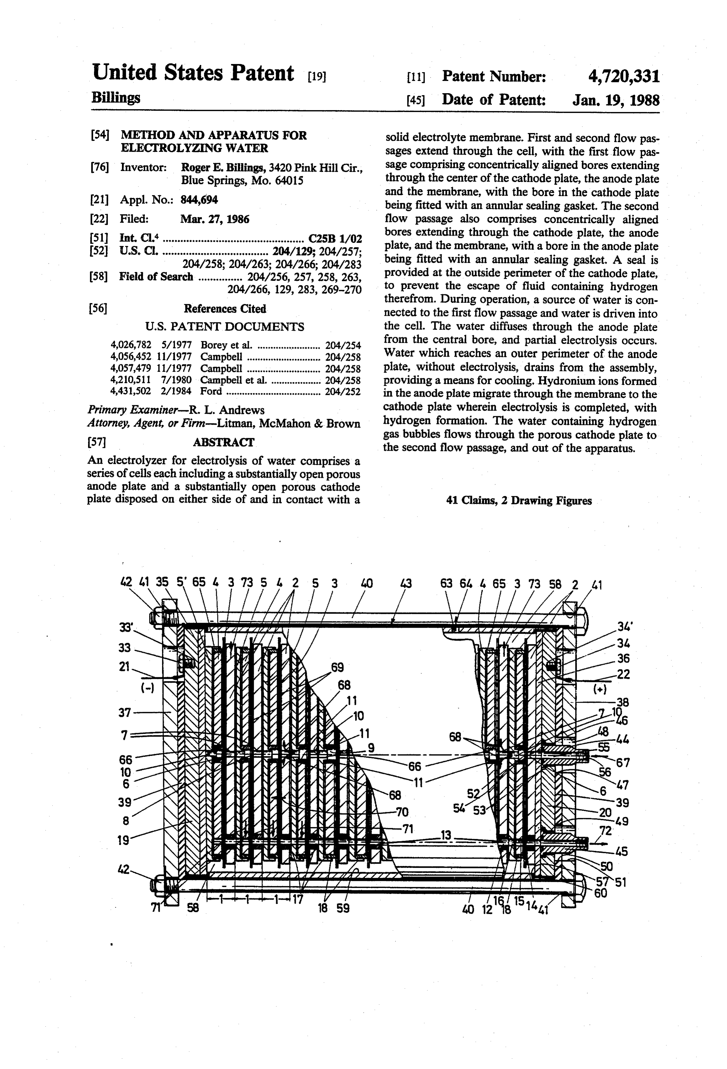
United States Patent (19) 11). Patent Number: 4,720,331 Billings 45 Date of Patent: Jan. 19, 1988 54 METHOD AND APPARATUS FOR solid electrolyte membrane. First and second flow pas ELECTROLYZNG WATER sages extend through the cell, with the first flow pas 76 Inventor: Roger E. Billings, 3420 Pink Hill Cir., sage comprising concentrically aligned bores extending Blue Springs, Mo. 64015 through the center of the cathode plate, the anode plate 21 Appl. No.: 844,694 and the membrane, with the bore in the cathode plate being fitted with an annular sealing gasket. The second 22 Filed: Mar. 27, 1986 flow passage also comprises concentrically aligned 51 int. Cl.'................................................ C25B 1/02 bores extending through the cathode plate, the anode 52 U.S.C. .................................... 204/129; 204/257; plate, and the membrane, with a bore in the anode plate 204/258; 204/263; 204/266; 204/283 being fitted with an annular sealing gasket. A seal is 58) Field of Search ............... 204/256, 257, 258, 263, provided at the outside perimeter of the cathode plate, 204/266, 129, 283, 269-270 to prevent the escape of fluid containing hydrogen
therefrom. During operation, a source of water is con nected to the first flow passage and water is driven into
4,026,782 5/1977 Borey et al. ........................ 204/254 from the central bore, and partial electrolysis occurs. 4,056,452 11/1977 Campbell ............................ 204/258 Water which reaches an outer perimeter of the anode 4,057,479 11/1977 Campbell ............................ 204/258 plate, without electrolysis, drains from the assembly, 4,210,511 7/1980 Campbell et al. ................... 204/258 providing a means for cooling. Hydronium ions formed 4,431,502 2/1984. Ford .................................... 204/252 in the anode plate migrate through the membrane to the Primary Examiner-R. L. Andrews cathode plate wherein electrolysis is completed, with Attorney, Agent, or Firm-Litman, McMahon & Brown hydrogen formation. The water containing hydrogen 57 ABSTRACT gas bubbles flows through the porous cathode plate to the second flow passage, and out of the apparatus.
An electrolyzer for electrolysis of water comprises a series of cells each including a substantially open porous anode plate and a substantially open porous cathode plate disposed on either side of and in contact with a 41 Claims, 2 Drawing Figures
42 4 35 5' 65 4 3 73 5 2 5 3 43 63 64. A 65 3 73 SB 2 a.
'N , s:
R2&2S211NZ NZ-4 5 st- 7 E. 67
N/N2. 2$1NZN-N- S.
SAS 49
2NZaza Sz 22 7.
YAAizst
Ns EFFFer
Page 2
AirAl 7 KAN (XSSASSESS It'? R N7
3 NG SEESSEN SYSSN NSS
NSN Nitti
N SNYSSYNS
NHSco
2 NNNNN,
Egype See heCN
g C Lala NI :
NaNSNNsing ZAZ (Z CeeCeezzassezze at
SNNNNNNNNNNNSSESN
essessessess SriSallerseasuyu qm
NSN
N 7S75 NSNNNYNNNNNNNNNYS as
Page 3
Drawing sheet — no readable text.
Page 4
more reliable and less costly than the known electroly
METHOD AND APPARATUS FOR sers of the prior art.
ELECTROLYZNG WATER A further objective of the invention is to provide an electrolyser which has improved means for supplying
BACKGROUND OF THE INVENTION 5 liquid to the anode plates and for withdrawing fluid and The present invention is relating to an electrolyser theAproducts formed at the anode and cathode plates. still further objective of the invention is to provide and to an electrode structure in such electrolyser. a new method for electrolysis of a liquid consisting of The invention consists also in a method for electroly water to produce hydrogen and oxygen therefrom. sing water by using such electrolyser. 10 Additional objectives are to provide a very compact The technology of producing hydrogen by the elec electrolyser which moreover enables to obtain hydro trolysis of water dates back to the last century. Conven gen at relative high pressure.
tionally the process is accomplished by placing elec trodes into a water solution containing electrolyte mate SUMMARY OF THE INVENTION rial (potassium hydroxide or hydrochloric acid). When 15 an appropriate electrical current is passed through the tionTheareabove and other objectives of the present inven realized in an electrolyzer comprising a single electrodes, oxygen bubbles form on one electrode and cell or a plurality of cells arranged in series. Each cell hydrogen on the other. Commercial electrolysis equip comprises an electrode structure made up of an anode ment has been manufactured utilizing this technology plate, a cathode plate and a solid electrolyte membrane, for many years. Recently, researchers have substituted 20 which are secured together in side-by-side relationship. a solid polymer type membrane material between two If the electrolyser comprises a plurality of cells which electrodes thereby making possible the electrolysis of have been assembled as a unitary multi-celled unit, sepa pure water with the advantage of more efficient conver rator plates are positioned between the anode and cath sion and lower cell maintenance costs. The solid poly ode plates of adjacent cells.
mer electrolyte also provides the capability of produc 25 In accordance with the invention, a single cell or ing hydrogen at high pressure, thereby eliminating the each individual cell comprises:
need for expensive and energy intensive secondary substantially open porous anode and cathode plates compressors. which are disposed on either side of and in contact with Such solid polymer electrolytes (SPE) have been a solid electrolyte membrane, said anode and cathode disclosed in following publications: "Solid Electrolytes 30 plates being composed of an electrically conductive Offer Route to hydrogen', Chemical and engineering material capable of being permeated by a liquid such as News, Aug. 27, 1973; "Electrolytic Hydrogen fuel Pro water;
duction with Solid Polymer Electrolyte Technology' a first flow passage comprising concentrically aligned by W. A. Titterinton and A. P. Fickett, VIII IECEC 35 bores, extending substantially through the center of said Proceedings; and "A Hydrogen-Energy System', pub cathode plate, anode plate and membrane, with the bore lished by American Gas Association, 1973. As de gasket; in said cathode plate being fitted with an annular sealing scribed in these references, SPE is typically a solid a second flow passage comprising also concentrically plastic sheet of perfluorinated sulfonic acid polymer aligned bores but extending eccentrically through the which, when saturated with water, becomes an excel 40 lent ionic conductor. The ionic conductivity results cathodethe bore plate, the anode plate and the membrane, with in said anode plate being fitted with an annular from the mobility of the hydrogen ions which move through the polymer sheet bypassing from one sulfonic sealing gasket;
sealing means at the outside perimeter of the cathode acid group to another. An anode and cathode are posi tioned on either side of the sheet and pressed there 45 plate; means for securing the cathode plate, membrane and against to form the desired SPE cell.
Electrolysis apparatus utilizing such SPE cell are anode means plate in firm side-by-side series engagement;
for applying to said first flow passage a liquid described in U.S. Pat. Nos. 4,056,452 and 4,210,511. flowing substantially radially through said porous In these patents the anode plates present in one of anode plate and wetting the membrane, so that the their sides alternating ridges and grooves. This makes 50 products produced at the interface of the membrane and the anode plates costly, as grooves are very expensive anode plate diffuse through the porous anode plate and to fabricate.
are carried radially
Moreover, especially in the electrolyser of U.S. Pat. perimeter of the anode away with the liquid to the outside No. 4,210,511 so called back-up rings are used for sup the interface of the membrane plate, and products produced at porting the outer O-rings which are required to seal the 55 diffuse through the porous cathode and the cathode plate outer perimeter of the cathodes and to prevent the es flow passage; and plate to said second cape of hydrogen. means for applying a D.C. current to the cathode and These back-up rings have been traditionally ma anode plates.
chined out of fiber glass and are thus very expensive. Preferably, both sides of the anode plate are com Moreover, on several occasions they have ruptured pletely flat.
while the electrolyser was in use causing severe damage In another embodiment of the invention the electro to the cell. In addition, very tight tolerances must be lyte structure for electrolysis apparatus comprises: maintained in the fabrication of these back-up rings in anode and cathode plates which are disposed on ei order to achieve proper sealing. These tight tolerances ther side of and in contact with a solid electrolyte mem on such a large diameter have made the back-up rings 65 brane, said anode and cathode plates being composed of one of the most expensive parts of the cell. an electrically conductive material, whereby at least the It is one of the principal objectives of the present cathode plate is capable of being permeated by a liquid invention to provide an improved electrolyser which is such as water, at least one flow passage comprising
Page 5
concentrically aligned bores, extending through said distributed over the whole volume of the substrate of cathodic plate, anode plate and membrane; which the anode and cathode plates are made. a separator or supporting plate composed of solid Preferably these plates are made of sintered titanium. non-porous electrically conductive material which is The different cells 1 are generally identical and are positioned with one side thereof in contact with the side 5 connected in series by means of a separator plate 5 of the cathode plate opposed to the side faced to the composed of a solid non porous electrically conductive membrane, said plate having means at its perimeter for material, such as titanium.
holding an annular sealing gasket provided around the Such plate 5 is positioned between two successive outside perimeter of the cathode plate; means for secur cells 1, in front of the lateral side of each cathode plate ing the cathode plate, membrane, anode plate and sepa O 4 which is opposed to the side of this latter faced to the rator or supporting plate in firm side-by-side series ene adjacent membrane 3.
gagement; As can seen clearly from FIG. 1, the different anode means for applying a liquid wetting the anode plate plates 2, membranes 3, cathode plates 4 and separator and the membrane, so that the products produced at the 5 plates 5 are all coaxially aligned side-by-side, the one interface of the membrane and anode plate are carried against the other.
away with the liquid to the outside perimeter of the Moreover, two flow passages are penetrating anode plate, and products produced at the interface of through the different successive cells from one end of the membrane and the cathode plate diffuse through the the electrolyser to the opposed end thereof: porous cathode plate to said flow passage. (a) a first flow passage 6, comprising concentrically The invention is also relating to a method for elec 20 aligned bores 7, 8, 9 and 10, which extends through the trolysis a liquid consisting essentially of water to pro center of respectively each of the anode plates 2, the duce hydrogen and oxygen therefrom, which method membrane 3, the cathode plates 4 and the separator comprises: plates 5, with the bore 9 in each cathode plate 4, being positioning a solid electrolyte membrane between an 25 fitted with an annular sealing gasket 11, generally open porous anode plate and an open porous cathode formed of a O-ring, and plate, said anode and cathode plates contacting mutu (b) a second flow passage 12, which is parallel to the ally opposite sides of said membrane; first flow passage 6, comprising also concentrically wetting with water the surfaces of the anode and aligned bores 13, 14, 15 and 16 but extending eccentri - cathode plates, which abut said membrane, by conveye 30 cally through each of the anode plates 2, membrane 3, ing water substantially radially from the center of the cathode plates 4 and intermediate separator plates 5, anode plate through the porous structure of the latter in respectively, close to the perimeter of these membranes the direction of its perimeter; and and plates, with the bore 13 in each anode plate 2 being passing a current through said membrane from the fitted with an annular sealing gasket 17, such as an O anode plate to the cathode plate to generate hydrogen 35 ring, gas at the cathode plate and oxygen gas at the anode Moreover, sealing means, such as an O-ring 18, sur plate. round the outside perimeter of each cathode plate 4. BRIEF DESCRIPTION OF THE DRAWINGS The plurality of cells are further assembled between two end plates 19 and 20 composed of non porous elec
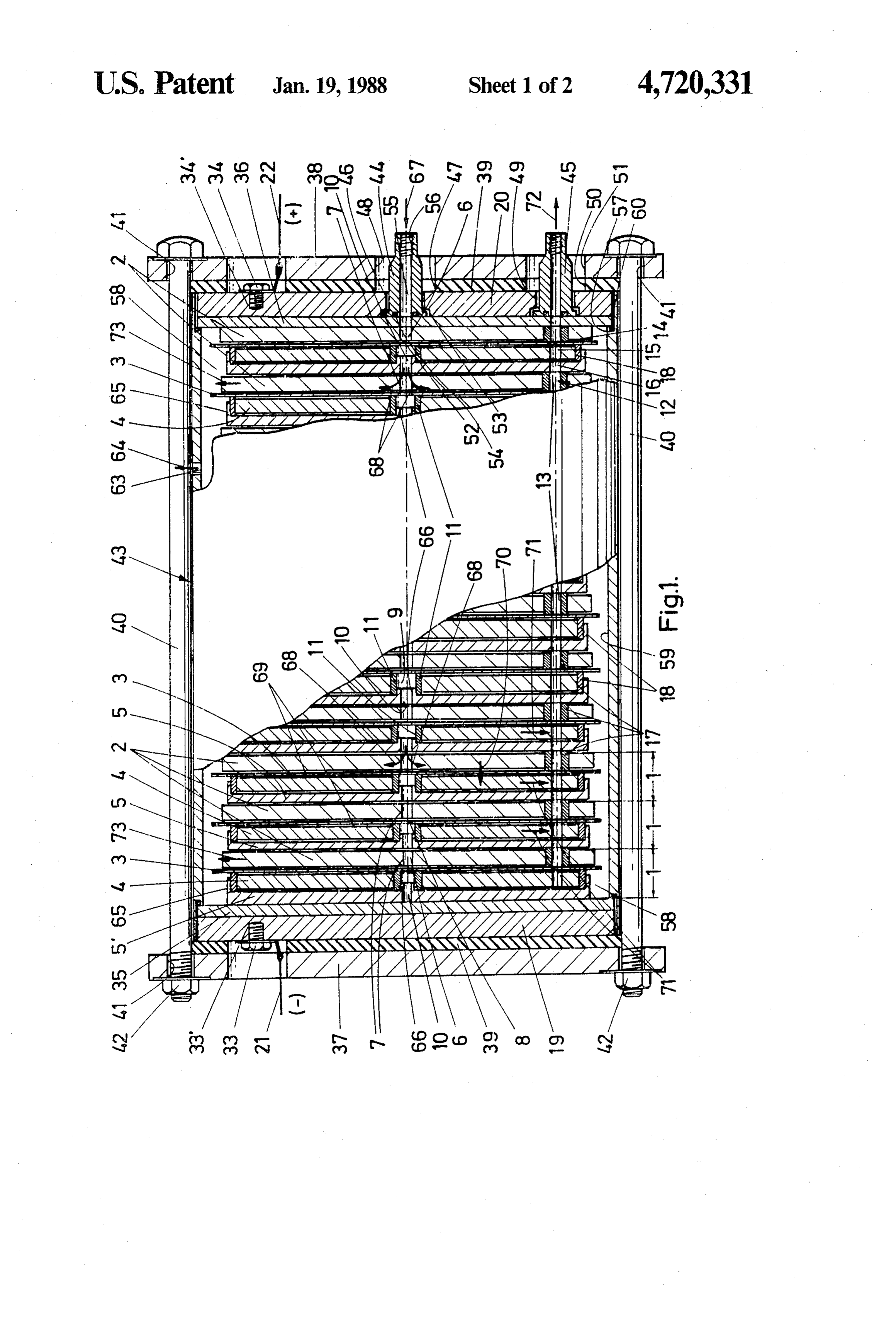
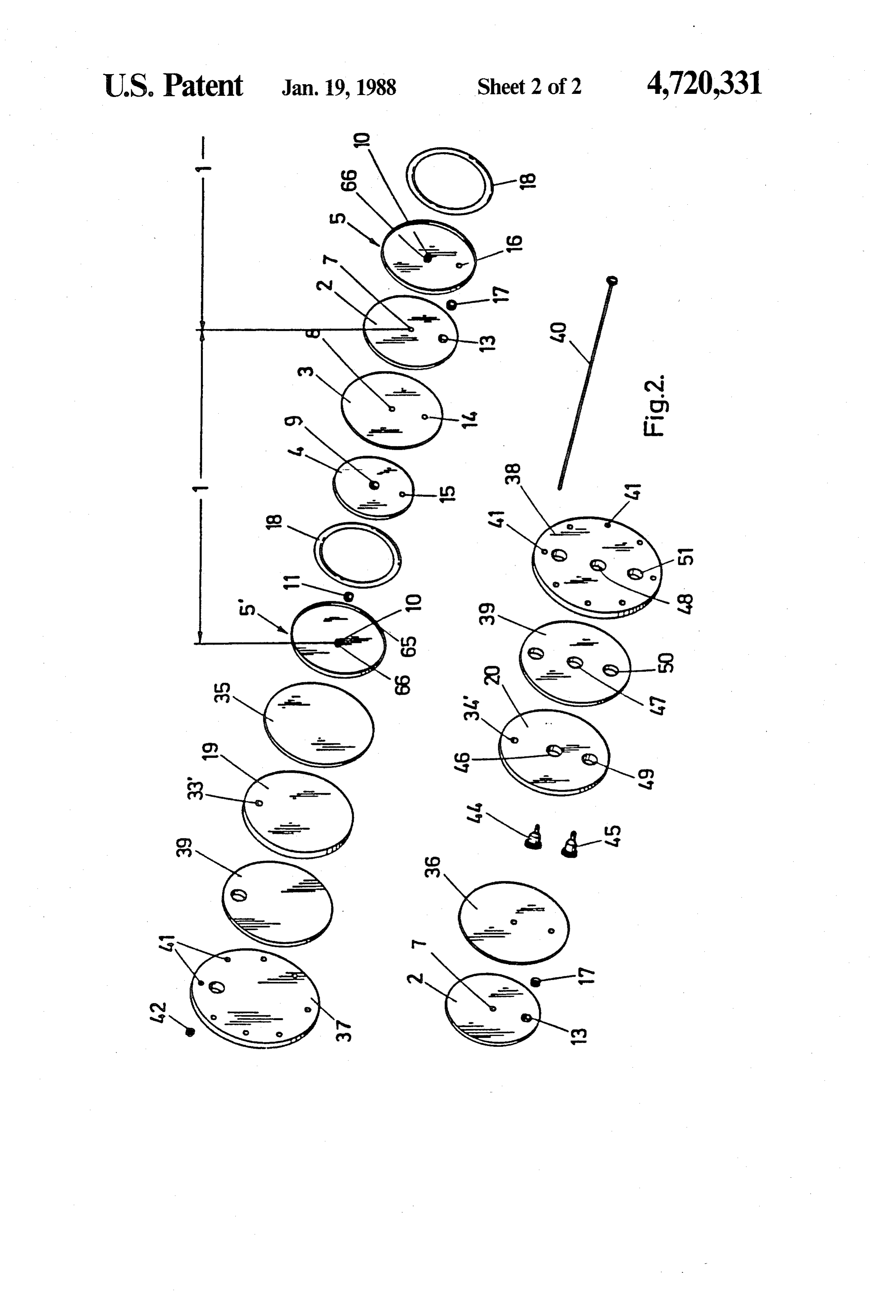
A preferred embodiment of the electrolyser and elec trically conductive material, such as aluminium. These trode structure thereof of this invention representing end plates are each connected to a D.C. potential by the best mode presently contemplated of carrying out means of an electrical conductor, respectively 21, 22 the invention in actual practice is illustrated in the ac which is fixed to a lug, respectively 33, 34. These lugs companying drawings in which: are treated in a bore 33' respectively 34, extending in FIG. 1 is a side elevational view, partially cut away 45 end plates 19 and 20. A source of positive voltage is with the cut away portion shown in vertical cross-sec applied to end plate 20 by the lug 34, while a source of tion, of the preferred electrolyser according to the in less positive voltage is applied to the end plate 19 by the vention; lug 33.
FIG. 2 is an exploded perspective view of a typical A current is passed from the end plate 20 to the series cell structure as used in the electrolyser of FIG. 1. 50 of the cells 1. Current passes from the anode plate 2 to In both drawings the same reference numbers are the cathode plate 4 of each cell. The voltage potential relating to the same parts. across the electrolyser from end plate 20 to end plate 19 DETAILED DESCRIPTION OF THE is theoretically evenly divided across the series of cells. ILLUSTRATED EMBODEMENT Therefore if f.i. the electrolyser contains ten cells, the 55 theoretical voltage potential between the cathode and
The preferred embodiment of the electrolyser shown anode of each cell will be equal to approximately 1/10 in the drawings comprises a plurality of successive cells of the voltage potential applied across the electrolyser 1, each of which being formed of an open porous anode between end plates 19 and 20. Especially for reasons of plate 2, a solid electrolyte membrane 3 and an open corrosion problems, it could be useful to separate each porous cathode plate 4. One side of the anode plate is in 60 end plate 19 and 20 from the adjacent end cell by means contact with one side of the membrane 3 and the other of an intermediate plate, respectively 35, 36, of corro side of this membrane is in contact with one side of the sion resistant non-porous electrically conductive mate cathode plate 4. These anode and cathode plates 2 and rial, such as titanium.
4 are composed of an electrically conductive material Further, a flange plate respectively 37,38, f.i. of steel, capable of being permiated by a liquid, such as water. 65 is applied flatwise against the outside of each end plate, By "open porous' it has to be understood that the respectively 19 and 20, while electrically insulating pours are communicating at random with each other so means are provided between the flange plates 37,38 and as to form flow channels which are substantially equally the adjacent end plates 19 and 20. The electrically insu
Page 6
lating means are preferably made of a resilient material, As shown in FIG. 2, in this preferred embodiment of such as a rubber plate 39. the invention, the anode plates 2, membranes 3, cathode The diameter of the flange plates 37 and 38 is substan plates 4, separator plates 5, end plates 19 and 20, inter tially larger than the diameter of the membranes and mediate plates 35 and 36, flange plates 37 and 38 and other plates, contained therebetween, the membranes 5 rubber plates 39 are all circular.
and plates are all pressed together between the flange 37 Moreover, the diameter of the membranes 3 is and 38 plates by means of tiebolts 40, which are extend slightly larger than the diameter of the anodes, so that ing through openings 41 spaced around the outer por they can be arranged side by side to said anode plates tion of the flange plates. These tie bolts are secured by with the perimeter of the membranes extending beyond nuts 42, which enable to urge towards each other the O the perimeter of the anode plates 2, while the cathode flange plates by tightening the nuts 42 on the tie bolts plates have a slightly smaller diameter than the anode 40, compressing thus on this way also the rubber plates plates 2.
39 and the different sealing gaskets. A cilindrical hous As to the separator plates they have a slightly larger ing 43 is positioned around the series of cells 1 in the 15 diameter than the cathode plates 4, without passing electrolyser unit between the flange plates, whereby the beyond the anode plates 2.
bolts 40 extend outside this housing 43. The cilindrical housing 43 is positioned around the As can be seen from FIG. 1, the first axial flow pas different cells forming an annular space or jacket 58 sage 6 extends from the intermediate plate 35, protect between the innerwall 59 of the housing and the cells. ing end plate 19, through all the cells until connecting 20 An opening 63 has further been provided in this housing means 44, provided at the opposed end of the electroly 43 for withdrawing fluid from the cells. It has to be ser, at which a non represented conductor can be at noted that this fluid could be used for cooling the elec tached. trolyser. A sealing O-ring 60 is located in an annular The free end of flow passage 6 is thus closed by recess 57 provided at each end of the housing, between means of intermediate plate 35. the latter and the intermediate plates 35 and 36. On a similar way, the free end of the second flow 25 The separator plates 5 and 5' which have to be con passage 12 is closed by means of the end separator plate sidered as very important parts of the electrolyser, ac 5. cording to the invention, have means at their perimeter The difference between the end separator plate 5, for holding the annular sealing gasket 18 around the also called "supporting plate', and the intermediate outside perimeter of the cathode plates 4. separator plates 5, positioned between the anode and 30 In the particular embodiment represented in the fig cathode plates of two successive cells, consists in the ures, separator plates 5 and 5' have a lip 65 extending fact that no bore 16 has been provided in this end sepa laterally at their side faced to the adjacent cathode plate rator plate 5", as clearly shown in FIG. 2. This means 4, which lip 65 supporting the outer perimeter of this that the second flow passage 12 is somewhat shorter 35 annular sealing gasket 18.
than the first flow passage 6. As already mentioned hereinabove, the intermediate The opposite end of the second passage 12 is also separator plates 5 have a central bore 16. According to extending until connecting means 45, provided at the the invention, this bore is also bordered by a lip 66 outside of the elctrolyser, at which also a non repre extending laterally on the separator plates 5, at same sented conduct can be attached. 40 side as lip 65 for holding the annular sealing gasket 11 As a result, only end plate 20, adjacent rubber plate fitting this bore 16.
39 and flange plate 38 have each two openings: opening Both lips 65 and 66 are preferably obtained simulta respectively 46, 47 and 48 and opening respectively 49, neously during a stamping operation by means of a 50 and 51. The first series of openings 46, 47 and 48 cutting tool which has been designed so as to create being coaxial with the first flow passage 6, while the 45 these lips, respectively around the outside perimeter other series of openings 49, 50 and 51 are coaxial with and around the central bore 16 of the separator plates 5. the second flow passage 12. By the fact that the lip 65 extends at the outside of the The connecting means 44 are formed by an insert annular sealing gasket 18, if a pressure is created inside having a flanged end 52 which is positioned in the series the cathode plate by the produced hydrogen gas, the lip of openings 46, 47 and 48. The flanged end 52 is fitted 50 65 will hold this gasket 18 in place. within a broader counterbore portion 53 of the opening Moreover, when the separator plates 5 and 5' are 46 in the end plate 20. A sealing ring 54 is provided pressed against the adjacent cathode plates 4, each gas within an appropriate receptacle in the inner face of the ket 18 will be compressed between a separator plate 5 insert 44, so as to realize a tight seal between the insert and a membrane 4, because the latter is supported later 44 and the intermediate plate 36 when pressing the end 55 ally on adjacent anode 2 having a larger diameter than plate 20 against the latter. the annular gasket 18. On this way there is no risk at all The connecting means 45 of the second flow passage that fluid, containing hydrogen, could escape into the 12 comprise a similar insert, which has also a flanged annular space 58.
end 52 disposed in a broader counter bore, wherein a Another also very important feature of the invention sealing ring 54 provides also a liquid and gas tight seal 60 is the structure of the anode plates 2, which are prefera between this insert and the intermediate plate 36. bly composed of a sintered metal substrate, such as Both inserts 44 and 45 are made of an appropriate titanium, having an open porosity between 30 and 80%, material and have a central bord 55 therethrough which preferably between 40 and 50%.
communicates with the corresponding flow passages, Indeed, it could be important that the anode plate is respectively 6 and 12. 65 very porous so as to enable that a liquid diffuses, on a The free end of each insert 44 and 45 extending out of substantially homogeneous way as a plug flow, from the the flange plate 38 is threated, as shown by reference 56, bore 13 provided in the center of the plate outwardly so that a conductor can be losely attached thereto. through the whole volume of the anode plate.
Page 7
It has been found that, on a very unexpected way, this charged with oxygen, is evacuated through opening 63 diffusion happens without any preferred direction, so of housing 43, as indicated by arrow 64. that it has not been necessary to provide grooves for Thanks to the very simplified design of each part of obtaining a regular distribution of the liquid flow the electrolyser and the resulting very compact con through the anode plate and at the interface of the latter 5 struction of the assembled cells, it has been possible to with the adjacent membrane. produce hydrogen at high pressure at the outlet, formed This has as important advantages, compared to the by insert 45.
known designs of similar anode plates, that: Moreover, the design allows for no cell-water or (a) all of the membrane material, forming the electro O hydrogen to come into contact with any metal inside lyte, is in contact with the anode plate, thereby resulting the cell except for titanium.
in a lower current density and a higher cell efficiency, This fact is very important for reducing corrosion so that less electricity is utilized by the cell, resulting in and electrolyte side reactions. a significant decrease in costs of generated hydrogen; Also, the fact that in flow passages 6 and 12 only (b) the fact that, on this way, the anode plate can be 15 simple O-rings have been used as sealing gaskets makes flat on both sides lowers considerably the fabrication it possible to apply high pressure inside flow passages 6 costs of the anode plates; and 12, without any risk of leackage. (c) by avoiding the grooves used in known anode It has to be understood that the invention has not to plates, it is possible to make them much thinner than in be restricted to the combination of the different features previous designs, which, of course, also results in a of the preferred embodiment of the electrolyser de substantial cost saving, the tickness of the anode plate is 20 scribed hereinabove and shown in the enclosed draw generally comprised between 0.5 mm and 1.5 mm, pref. 1ngs.
erably between 0.6 and 1 mm; It would fi be possible to combine the separator (d) the liquid diffusion within the sintered substrate is plates 5 and 5' having retaining means for the annular more uniform and a better coooling of the cell, eliminat 25 sealing gasket, with a known grooved anode plate. ing hot spots, is obtained; On a similar way, it could be possible, according to (e) a much easier method of connection of the liquid the invention, to combine an anode plate, as described inlet to the electrolyte plates can be realized. hereinabove, in a cell using back-up rings machined out Advantageously, at least the surface of the anode of fibreglas for retaining the sealing ring around the plates 2, which contacts the membrane is treated with 30 perimeter of the cathode plates, instead of the above catalyst coating, such as platinum, in a manner so that described separated plates with means for holding this the anode plates maintain their porosity. ring.
Referring in particular to FIG. 1, the use and work The relative dimensions, such as thickness, of the ing of the electrolyser, according to the invention, will different plates of the electrolyser, according to the be summarly described hereinafter for producing hy 35 invention, represented in the drawings, do not necessar drogen and oxygen by electrolysing of water. ily correspond to those which will be used in practice. Water is introduced under pressure in first flow pas Generally, the plates are very thin and can be less sage 6 through insert 44, as indicated by arrow 67. The than 0.5 mm.
water diffuses in the different anode plates from the In the preferred embodiment, each cell was described central bores 7, provide in each anode plate and delimit with the water inlet passageway located in the center of ing this passage 6, as indicated by the different arrows the circular cells, and with the water outlet passageway, 68. for flowing out of the water and hydrogen gas mixture, On this way, the water is conveyed radially from the eccentrically positioned. It will be understood that center of each anode plate 2 through the porous struc while this arrangement may be preferred, especially for ture of the latter, in the direction of its perimeter, so as 45 efficient use of a greater area of cathode and anode to wet completely the whole volume of the anode plates, the inlet passageway need not be centrally lo plates. This water further diffuses to the interface 69 cated. That is, the inlet passageway might be located in between the anode plates and the adjacent membranes, a position other than the centers of the anode plate, so as to wet also the latter. cathode plate and membrane; further, the outlet pas By applying a negative voltage to end plate 19 and a 50 sageway need not be eccentrically positioned, with positive voltage to end plate 20, an electrical current is respect to the centers. It will further be understood that produced within the different cells 1, so that the water in some applications of the instant invention non-circu is electrochemically decomposed at this interface 69 to lar plates and membranes may be used, with the remain provide oxygen and hydrogen ions, more particularly der of the assembly appropriately modified. hydronium ions. The hydrogen ions and/or hydronium 55 I claim:
ions move through the membrane 3, as indicated by 1. An electrode structure for electrolysis apparatus arrow 70. When these ions reach the cathode plate 4 comprising:
they combine with free electrons supplied by the cath substantially open porous anode and cathode plates ode plate to produce water and hydrogen gas. This which are disposed on either side of and in contact mixture of water and hydrogen is collected in second 60 with a solid electrolyte membrane, said anode and flow passage 12, as indicated by the different arrows 71, cathode plates being composed of an electrically and is evacuated at the flange plate 38, as indicated by conductive material capable of being permeated by arrow 72. a liquid, such as water; The excess of water fed to the anode plates 2, which a first flow passage comprising concentrically aligned has not crossed the membranes 3 or has not been de 65 bores, extending substantially through the center of composed at the interface 69, is discharged at the perim said cathode plate, anode plate and membrane, eter of each anode plate 2, as indicated by arrow 73, in with the bore in said cathode plate being fitted with the annular space 58. This water, which has been an annular sealing gasket;
Page 8
a second flow passage comprising also concentrically 11. An electrode structure according to claim 1, fur aligned bores but extending eccentrically through ther comprising a separator or supporting plate com the cathode plate, the anode plate and the mem posed of a solid non-porous electrically conductive brane, with the bore in said anode plate being fitted material, which is positioned with one side thereof in with an annular sealing gasket; contact with the side of the cathode plate opposed to sealing means at the outside perimeter of the cathode the side faced to the membrane, said plate having a plate; substantial central bore, which is coaxial with said first means for securing the cathode plate, membrane and flow passage and which is bordered by a lip extending anode plate in firm side-by-side series engagement; laterally on said plate, at the side thereof faced to the means for applying to said first flow passage a liquid 10 cathode plate, for holding the annular sealing gasket flowing into and substantially radially through said fitting the bore in the cathode plate for said first flow porous anode plate so as to cool the anode plate passage.
and wetting the membrane, so that the products 12. An electrode structure according to claim 1, fur produced at the interface of the membrane and 15 ther comprising a separator or supporting plate com anode plate diffuse through the porous anode plate posed of solid non-porous electrically conductive mate and are carried radially away with the liquid pass rial which is positioned with one side thereof in contact ing through the anode plate to the outside perime with the side of the cathode plate opposed to the side ter of the anode plate, and products produced at faced to the membrane, said plate having a first lip at its the interface of the membrane and the cathode outer perimeter extending laterally at its side faced to 20 the cathode plate and being able to support the outer plate diffuse through the porous cathode plate to said second flow passage; and perimeter of an annular sealing gasket extending around the outside perimeter of the cathode plate, the separator means for applying a D.C. current to the cathode and or supporting anode plates. plate composed of solid non-porous elec 2. An electrode structure according to claim 1, trically conductive material having further a substan wherein the anode plate is a sintered metal substrate or 25 tially central bore, which is coaxial with said first flow passage and which is also bordered by a second substan disc having a porosity between 30 and 80%, preferably tially similar lip extending laterally on this plate, at the between 40 and 50%.
3. An electrode structure according to claim 1 or 2, gasketside same as the first lip, for holding the annular sealing wherein at least the side of the anode plate faced to the 30 passage, both the fitting lips bore in the cathode plate for said first being obtained simultaneously during membrane is completely flat.
4. An electric structure according to claim 1, wherein has been designed so by a stamping operation
means of a cutting tool which to create said lips respectively both sides of the anode plate are completely flat.
5. An electrode structure according to claim 1, tially central bore of the plate.and around the substan around the outside perimeter wherein the thickness of the anode plate is comprised 35 13. An electrode structure according to claim 9, between 0.5 and 1.5 mm, preferably between 0.6 and 1 wherein the plate composed of solid non-porous electri
6. An electrode structure according to claim 1, cally conductive material is made of titanium. 14. An electrode structure for electrolysis apparatus wherein at least the surface of the anode plate, which comprising:
contacts the membrane is coated with platinum in a anode and cathode plates which are disposed on ei manner so that the anode plate maintain its porosity. ther side of and in contact with a solid electrolyte 7. An electrode structure according to claim 1, membrane, said anode and cathode plates being wherein the anode plate is made of sintered titanium. composed of an electrically conductive material, 8. An electrode structure according to claim 1, whereby at least the cathode plate is capable of wherein the cathode plate, the membrane and the anode 45 being permeated by a liquid such as water; plate are formed of coaxial mounted discs, an also coax at least one flow passage comprising concentrically ial liquid jacket being provided around the cathode aligned bores, extending through said cathode plate, the membrane and the anode for collecting and plate, anode plate and membrane; evacuating the liquid, which has been carried radially a or supporting plate composed of solid non-porous away through the anode plate at its perimeter. 50 electrically conductive material which is posi 9. An electrode structure according to claim 1, fur tioned with one side thereof in contact with the ther comprising a separator or supporting plate com side of the cathode plate opposed to the side faced posed of solid non-porous electrically conductive mate to the membrane, said cathode plate having retain rial which is positioned with one side thereof in contact ing means attached to and extending axially from with the side of the cathode plate opposed to the side 55 the entire circumference of the supporting plate faced to the membrane, said plate having means at its above the cathode plate at the perimeter of said perimeter for holding an annular sealing gasket pro supporting plate and an annular sealing gasket pro vided around the outside perimeter of the cathode plate. vided around the outside perimeter of the cathode 10. An electrode structure according to claim 1, fur plate radially interior of the retaining means and ther comprising a separator or supporting plate con 60 held in sealing relationship by the retaining means; posed of solid non-porous electrically conductive mate means for securing the cathode plate, membrane, rial which is positioned with one side thereof in contact anode plate and separator or supporting plate in with the side of the cathode plate opposed to the side firm side-by-side series engagement; faced to the membrane, said plate having a lip extending means for applying a liquid wetting the anode plate; laterally at its side faced to the cathode plate and being 65 and the membrane, so that the products produced at able to support the outer perimeter of an annular sealing the interface of membrane and anode plate are gasket, which gasket extending around the outside pe carried away with the liquid to the outside perime rimeter of the cathode plate. ter of the anode plate, and products produced at
Page 9
the interface of the membrane and the cathode sealing means at the outside perimeter of each cath plate diffuse through the porous cathode plate to ode plate;
said flow passage. means for securing all the cathode plates, membranes, 15. An electrode structure according to claim 14, intermediate separator plates and anode plates in wherein the separator or supporting plate composed of 5 firm side-by-side series engagement; solid non-porous electrically conductive material has a means for applying to said first flow passage a liquid lip extending laterally at its side faced to the cathode flowing substantially radially into and through plate and being able to support the outer perimeter of an each porous anode plate so as to cool the anode annular sealing gasket, which gasket extending around plates and wetting the adjacent membrane, so that the outside perimeter of the cathode plate. O the products produced at the interface of each 16. An electrode structure according to claim 14, anode plate and adjacent membrane of each cell wherein the separator or supporting plate composed of diffuse through each anode plate and are carried a solid non-porous electrically conductive material has radially away through the anode plate with the a substantial central bore, which is coaxial with said first liquid to the outside perimeter of the anode plate, flow passage and which is bordered by a lip extending 15 and products produced at the interface of each laterally on said plate, at the side thereof faced to the cathode plate and adjacent membrane diffuse cathode plate, for holding the annular sealing gasket through said cathode plate to said second flow fitting the bore in the cathode plate for said first flow passage; and .
passage. means for applying a D.C. current to the anode and 17. An electrode structure according to claim 14, 20 cathode plates.
wherein the separator or supporting plate composed of 19. Electrolyser according to claim 18, wherein the solid non-porous electrically conductive material has a anode plates are sintered metal substrates or discs hav first lip at its outer perimeter extending laterally at its ing a porosity between 30 and 80%, preferably between side faced to the cathode plate and being able to support 40 and 50%.
the outer perimeter of an annular gasket extending 25 20. An electrolyser according to claim 18 or 19, around the outside perimeter of the cathode plate, the wherein at least the side of the anode plates faced to the separator or supporting plate composed of solid non adjacent membranes is completely flat.
porous electrically conductive material having further a 21. An electrolyser according to claim 18, wherein bore, which is coaxial with said flow passage and which both sides of the anode plates are completely flat. is also bordered by a second substantially similar lip 30 22. An electrolyser according to claim 18, wherein extending laterally on this plate, at the same side as the the thickness of the anode plates is comprised between first lip, for holding the annular sealing gasket fitting the 0.5 and 1.5 mm, preferably between 0.6 and 1 mm. bore in the cathode plate for said flow passage, both lips 23. An electrolyser according to claim 18, wherein at being obtained simultaneously during a stamping opera least the surface of the anode plates, which contact the tion by means of a cutting tool which has been designed 35 adjacent membrane, is coated with platinum in a man so as to create said lips respectively around the outside ner so that the anode plates maintain their porosity. perimeter and around the bore of the plate. 24. An electrolyser according to claim 18, wherein 18. An electrolyzer comprising: the anode plates are made of sintered titanium. a plurality of successive cells each of which compris 25. An electrolyser according to claim 18, wherein ing a substantially open porous anode plate, a solid the cathode plates, the membranes and the anode plates electrolyte membrane and a substantially porous are formed of coaxial mounted discs, an also coaxial cathode plate, with one side of the anode plate liquid jacket being provided around the plurality of being in contact with one side of the membrane and cells for collecting and evacuating the liquid, which has the other side of said membrane being in contact been carried radially away through the anode plates, at with one side of the cathode plate, said anode and 45 their perimeter.
cathode plates being composed of an electrically 26. An electrolyser according to claim 18, wherein conductive material capable of being permeated by said separator plates have means at their perimeter for a liquid such as water, said cells being connected in holding an annular sealing gasket provided around the series with separator or supporting plates com outside perimeter of each of the cathode plates. posed of solid non-porous electrically conductive 50 27. An electrolyser according to claim 18, wherein material positioned in front of the lateral side of said separator plates have a lip extending laterally at each cathode plate, which is opposed to the side of their side faced to the adjacent cathode plates and being said cathode faced to the adjacent membrane, the able to support the outer perimeter of an annular sealing anode plates, membranes, cathode plates and sepa gasket, which gasket extending around the outside pe rator plates all being coaxially aligned side-by-side 55 rimeter of each of the cathode plates. the one against the other; 28. An electrolyser according to claim 18, wherein a first flow passage comprising concentrically aligned said separator plates each have substantially central bores extending substantially through the center of bore, which is coaxial with said first flow passage and each of said cathode plates, membranes, intermedi which is bordered by a lip extending laterally on said ate separator plates and anode plates, with the bore 60 plates, at the side thereof faced to the adjacent cathode in each cathode plate being fitted with an annular plate, for holding the annular sealing gasket fitting the sealing gasket; bore in this cathode plate for said first flow passage. a second flow passage comprising also concentrically 29. An electrolyser according to claim 18, wherein aligned bores but extending eccentrically through said separator plates have a first lip at their outer perim each of said cathode plates, membranes, intermedi- 65 eter, extending laterally at their side faced to the adja ate separator plates and anode plates with the bore cent cathode plates and being able to support the outer in each anode plate being fitted with an annular perimeter of an annular sealing gasket extending around sealing gasket; the outside perimeter of the cathode plates, said separa
Page 10
tor plates having further a substantially central bore, an eccentric bore therethrough from one side which is coaxial with said first flow passage and which thereof to the other; a solid electrolyte membrane is also bordered by a second substantially similar lip having the same general shape as the anode plate extending laterally on this plate, at the same side as the but with a slightly larger diameter, so that the first lip, for holding the annular sealing ring fitting the 5 membrane can be arranged side-by-side to said bore in the cathode plates for said first passage, both lips anode plate with the perimeter of the membrane being obtained simultaneously during a stamping opera extending beyond the perimeter of the anode plate, tion by means of a cutting tool which has been designed the membrane having also a central bore and an so as to create said lips respectively around the outside eccentric bore therethrough from one side thereof perimeter and around the substantial central bore of the O to the other;
separator plates. a cathode plate composed of an open porous electri 30. An electrolyser according to claim 18, wherein cally conductive material, said cathode plate hav the separator plates are made of titanium. ing the same general shape as said anode plate and 31. An electrolyser according to claim 18, wherein said membrane but having a slightly smaller diame the plurality of cells are assembled between two end 15 ter than the anode plate, the cathode plate having plates composed of a non-porous electrically conduc also a central bore and an eccentric bore there tive material, means being provided for connecting a through from one side thereof to the other; D.C. potential to one of the end plates and a D.C. poten a separator plate composed of solid non-porous elec tial, which is negative with respect to said first poten trically conductive material positioned in front of tial, to the other end plate. 20 the lateral side of each cathode plate, which is 32. An electrolyser according to claim 31, wherein opposed to the side of said cathode faced to the each end plate is separated from the adjacentend cell by adjacent membrane, the separator plate having the means of an intermediate plate of corrosion resistant same general shape as the cathode plate but with a non-porous electrically conductive material, of tita slightly larger diameter than the cathode plate, and
33. An electrolyser according to claim 31, wherein a having an axial extension from the perimeter of the flange plate is applied flatwise against the outside of separator plate extending over the entire circum each end plate, electrically insulating means being pro ference of the cathode plate, the separator plates, vided between the flange plates and the adjacent end except the separator plate positioned at the outside plate. 30 of the end cell, in front of the end cathode plate, 34. An electrolyser according to claim 33, wherein having a substantial central bore and an eccentric the electrically insulating means are made of a resilient bore therethrough from one side thereof to the material, of rubber. other; a first sealing gasket, one sealing gasket for 35. An electrolyser according to claim 18, wherein each cathode plate, said gasket being maintained by said first and said second flow passages extend through 35 the separator plate extension in sealing relation said plurality of successive cells, from one end thereof over the associated cathode plate and being to the other, both flow passages being closed at the adapted to circumscribe the outside perimeter of outside of the same end cell and crossing the opposed said cathode plate;
end cell untill connecting means are reached provided a second annular sealing gasket fitted in the central at the outside of the electrolyser, at which a conductor 40 bore of each cathode plate; can be attached. a third annular sealing gasket fitted in the eccentric 36. An electrolyser according to claim 33, wherein at bore of each anode plate;
least one end plate and the adjacent flange plate have at means for securing the anode plate, the solid electro least an opening which is coaxial with one of said flow lyte membrane and the cathode plate in side-by passages, an insert having a flanged end being posi 45 side relationship to form a cell, wherein one side of tioned in said openings, the flanged end fitting within a the anode plate is in contact with one side of the broader counterbore portion of said opening in the end solid electrolyte membrane and the other side of plate and cooperating tight with the adjacent intermedi said membrane is in contact with one side on the ate plate, the insert having a central bore therethrough cathode plate, with said anode plate, solid electro which communicates with said flow passage, means 50 lyte membrane and separator plate being aligned so being provided at the insert so that a conduct can be that the respective central bores therethrough are attached thereto. in concentric alignment to form a first flow passage 37. An electrolyser according to claim 33, wherein extending through the cell and the eccentric bores only one end plate and the adjacent flange plate have therethrough are in concentric alignment to form a each two openings therethrough, the first openings 55 second flow passage extending through the cell, being coaxial with said first flow passage, the second substantially in a parallel direction with the first opening being in communication with said second flow flow passage; a cylindrical housing positioned passage, an insert having a flanged end being positioned around the cell and forming an annular space in each said pair of coaxial first and second openings around the cell wherein liquid, flowing radially and cooperating tight with the adjacent intermediate through the porous anode plate from the central plate, said inserts having a central bore therethrough bore provided in the latter in the direction of its which communicates with the corresponding flow pas perimeter, can be collected; sage, means being provided at each insert so that a means for conveying a liquid to said first passage so as conductor can be attached thereto. to enable the liquid to flow through the porous 38. An elecrolyzer comprising: 65 anode plate;
an anode plate composed of an open porous, electri first means for evacuating liquid and products pro cally conductive material, said anode plate being duced at the interface of the membrane and anode circular and having a substantial central bore and plate and collected in said annular space;
Page 11
second means, in combination with said second flow conductive material capable of being permeated by passage, for receiving products produced at the a liquid, such as water;
interface of the membrane and cathode plate; and a first flow passage comprising concentrically aligned means for applying a D.C. current to the anode and bores, extending substantially through each of said cathode plates. 5 cathode plate, anode plate and membrane, with the 39. A method for electrolysis of a liquid consisting bore in said cathode plate being fitted with an an essentially of water to produce hydrogen and oxygen nular sealing gasket;
therefrom, said method comprising: a second flow passage also comprising a second set of positioning a solid electrolyte membrane between an 10 concentrically aligned bores passing through each open porous anode plate and an open porous cath of said cathode plate, anode plate and membrane, ode plate, said anode and cathode plates contacting with the bore in the anode plate being fitted with an mutually opposite sides of said membrane; annular sealing gasket;
wetting with water the surfaces of the anode and sealing means at the outside perimeter of the cathode plate;
cathode plates, which abut said membrane, by con 15 means for securing the cathode plate, membrane and veying water substantially radially from the center anode plate in firm side-by-side series engagement; of the anode plate into and through the open po means for applying to said first flow passage a liquid rous structure of the anode plate in the direction of flowing substantially radially into and passing its perimeter; and through said porous anode plate and wetting the passing a current through said membrane from the membrane, so that the products produced at the anode plate to the cathode plate to generate hydro interface of the membrane and anode plate diffuse gen gas at the cathode plate and oxygen gas at the into and substantially pass through the porous anode plate. anode plate with the liquid passing through the 40. A method according to claim 39, wherein an anode plate and are carried radially away with the anode plate is used which presents two substantially flat 25 liquid to the outer perimeter of the anode plate, and sides. products produced at the interface of the mem 4. An electrode structure and electrolysis apparatus brane and the cathode plate diffuse through the comprising: porous cathode plate to said second flow passage; substantially open porous anode and cathode plates and which are disposed on either side of and in contact 30 means for applying a D.C. current to the cathode and with a solid electrolyte membrane, said anode and anode plates.
cathode plates being composed of an electrically k is is
Provenance
- Collection
- Cited prior art
- Original PDF
- patentimages.storage.googleapis.com →
- Filed
- 1986-03-27
- Pages
- 11
- Method
- pdftotext (the PDF's own text layer) + pdftoppm 300dpi page scans
- Source
- Google Patents bibliographic record
- Granted
- 1988-01-19
- Inventors
- Roger E. Billings
- Transcribed from
- patentimages.storage.googleapis.com →