Figure (11-3)
Figure (11-3)
How it is written
- (11-3) 9×
Drawings 1
-
(1030) of figure (11-3) · Voltage Flexing Process
On this figure 15
- 952 Stationary Voltage Fields
- 954 Physical Stress
- 956 Voltage Fields
- 957 Primary Input Coil
- 1002 VIC Coil-Array
- 1003 VIC Coil Assembly
- 1004 Bipolar Water Molecules
- 1006 Bipolar Water Molecules
- 1030 —
- 1050 Voltage Energized Thermal Transference Effect
- E13 Stationary Positive Voltage Plate
- E15 Electrical Voltage Fields
- EI3 Voltage Zone
- EI4 —
- EI6 —
Where it is named · 9
Voltage Flexing Process 2×
VIC Switchover Circuit 7×
-
(1030) of Figure (11-3)
-
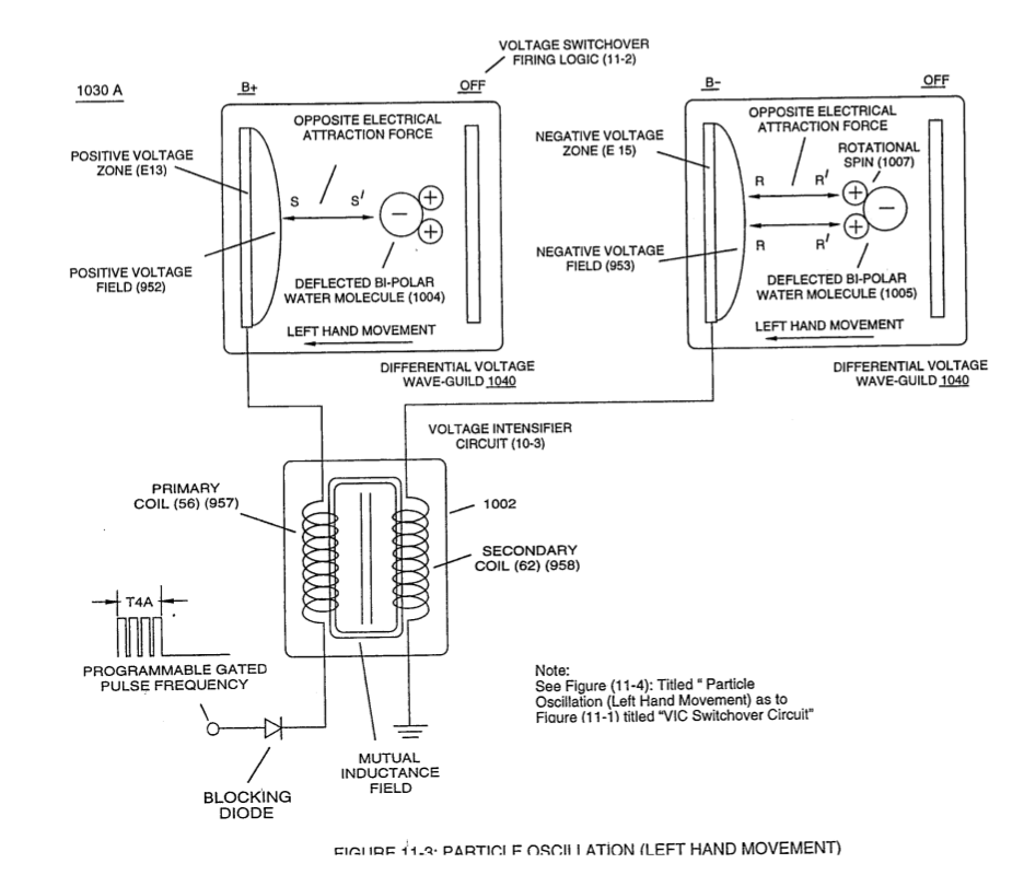
When incoming programmable gated pulse-frequency waveform (T4A) of Figure (11-2) electrically energizes primary input coil (957) of Figure (11-3) to produce positive voltage field (952) across voltage zone (EI3), the bipolar electrical charged water molecule having a negative charged oxygen atom is deflected and moved toward stationary positiv …
-
primary input coil (957) of Figure (11-3)
-
To reverse direction of the line of travel of the deflecting water molecule from left-hand movement to right-hand movement, another and completely separate Voltage Intensifier VIC-Coil Assembly (1003) of Figure (11-3) is periodically switched-on electrically by alternate voltage pulse waveform (T4B) once first voltage pulse wave-form (T4A) is terminated for a brief period of time (T3A)
-
... duplicating the electrical attraction force (S-S' !R-R') as before except both bipolar water molecule (s) (1004/1006) are, now, redirected and deflected in the opposite direction toward voltage fields (956/954), respectfully, as so illustrated in (1030) diagram (B) of Figure (11-3).
-
Electrically interfacing alternate "Switchover" voltage pulse wave-form (T4A/T4B) to each of both VIC Coil-Array (s) (1002/1003) of Figure (11-3) as schematically depicted, now, forms VIC Switchover Circuit (1010) of Figure (11-1).