(E15)
Electrical Voltage Fields
Where it is first named
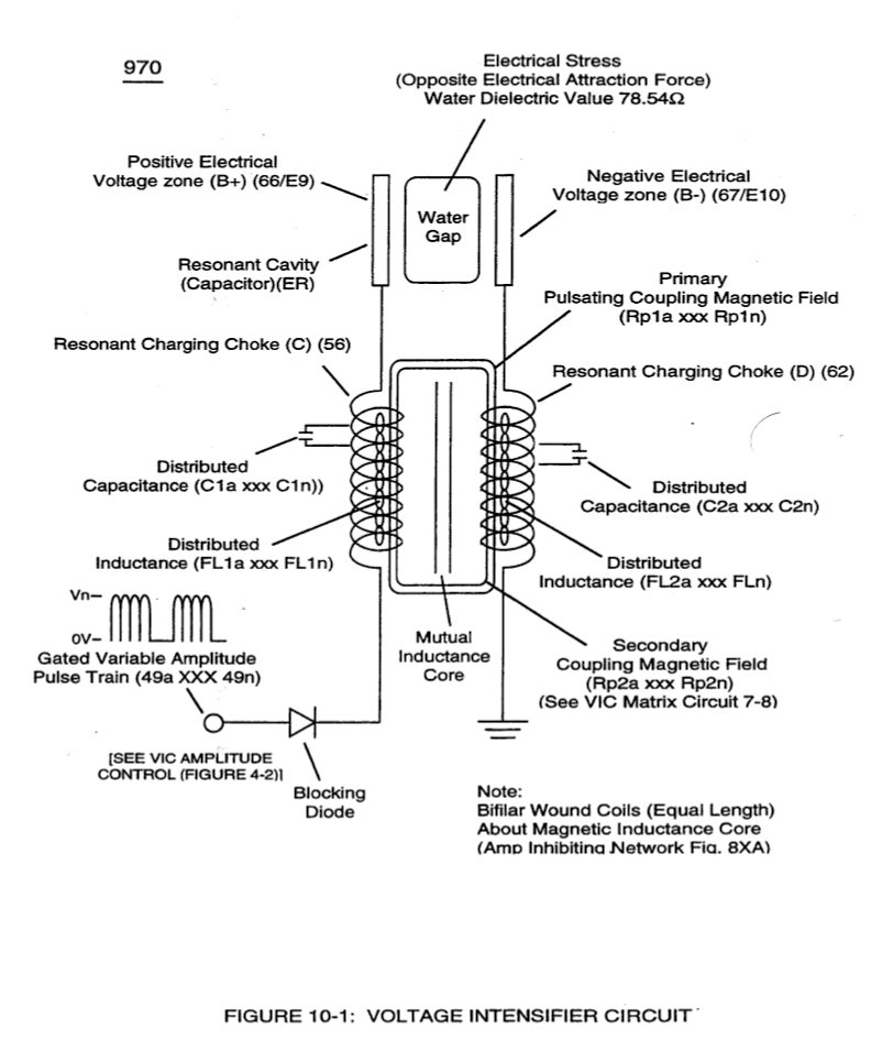
… able atom occurs when opposite electrical attraction forces (RU-RU' / ST'-ST) are set up between the electrical charged sub-particles of the atom and the recurring pulsating electrical voltage fields (E15/E16) of opposite electrical polarity of potential (B+/B-), as so illustrated in (1020) of Figure (11-1) titled “Neutron Electrical Polarization Process” as to Figure (10-1) titled “Voltage Intensifi …
How it is written
- (E15/E16) 2× with (E16) Electrical Voltage Fields
- (954/E15 – 956/E16) 1× with (954) Physical Stress, (956) Voltage Fields, (E16) Electrical Voltage Fields
- (E13-EI4 - E15-EI6) 1× with (E13) Stationary Positive Voltage Plate, (EI4), (EI6)
- (E15/954) 1× with (954) Physical Stress
Drawings 4
-
Carries this number · WFC 430-2 Illustrations
-
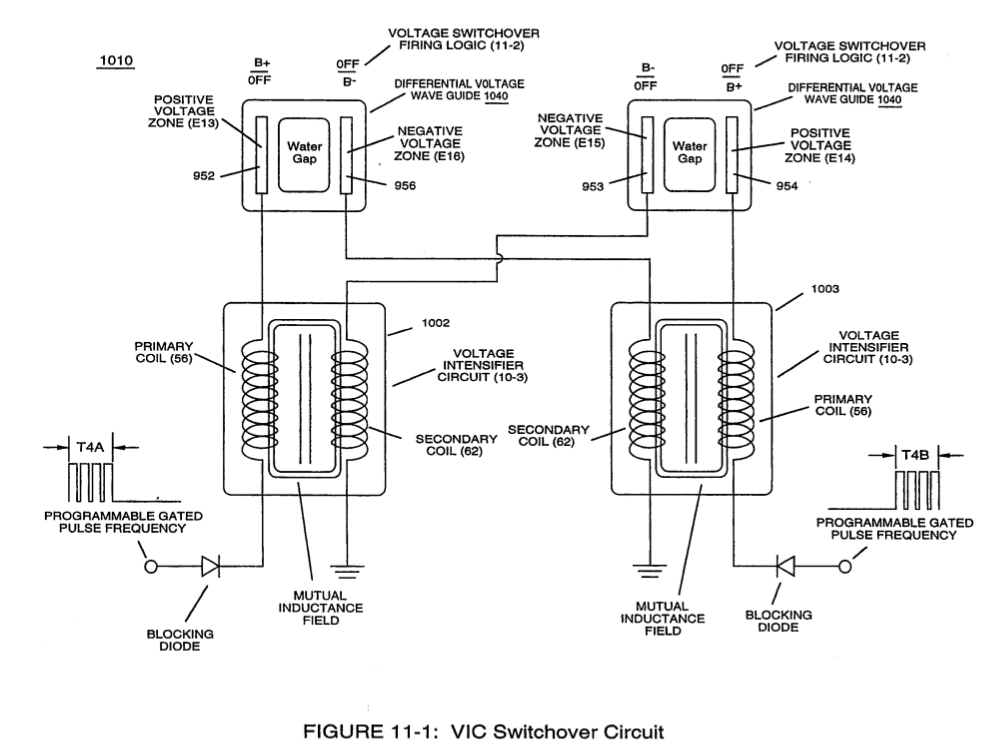
dual unipolar voltage pulse circuit (1010) of Figure (11-1) · Voltage Flexing Process
-
(1030) of figure (11-3) · Voltage Flexing Process
-
"Voltage Energized Thermal Transference Effect" (1050) of Figure (11-5) · Voltage Flexing Process
Where it is named · 5
Wobbling Effect 2×
-
electrical voltage fields (E15/E16)
… able atom occurs when opposite electrical attraction forces (RU-RU' / ST'-ST) are set up between the electrical charged sub-particles of the atom and the recurring pulsating electrical voltage fields (E15/E16) of opposite electrical polarity of potential (B+/B-), as so illustrated in (1020) of Figure (11-1) titled “Neutron Electrical Polarization Process” as to Figure (10-1) titled “Voltage Intensifi …
-
When applied, the opposite voltage fields (E15/E16) overcomes the electrovalent bonding force (qq') that exists between the two unlike electrical charged subatomic particles forming the neutron
Voltage Flexing Process 1×
-
... whichever the case may be, the applied stationary voltage fields (952/E13 – 953/E14) or (954/E15 – 956/E16) alternately switch over periodically superimposes electrical stress forces (S-S' and R - R') onto the energy spectrum of the water molecule atom (s )(210) while physical flexing (951) of Figure (11-5) of the water molecule atom (s) occurs
VIC Switchover Circuit 2×
-
VIC Switchover Circuit (1010) of Figure (11-1) is utilized to bring about Voltage Flexing Process (1050) by preventing amp influxing into and away from the separate and periodically spaced (-) voltage zones (E13-EI4 - E15-EI6) of diagram (1030) of Figure (11-3) as to (1010) of Figure (11-1);
-
Pairing together positive voltage zone (E13/952) with negative voltage zone (E16/956) and doing the same with voltage-surfaces (E14/953) to (E15/954) as so graphically shown in (1O1O) of Figure (11-1) and each having an longitudinal axis of identical length, now, individually forms what is called hereinafter a "Differential Voltage Wave-guide" (1040)