(990)
Voltage Intensifier Circuit
Where it is first named
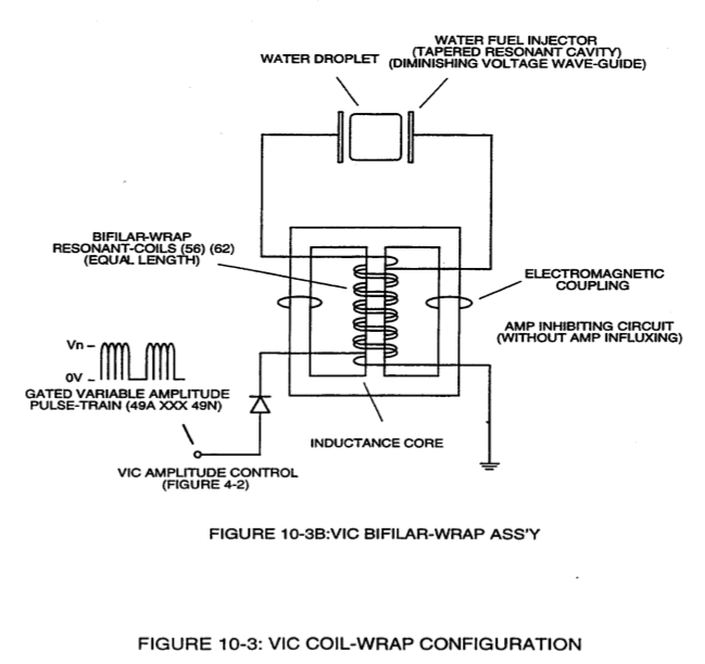
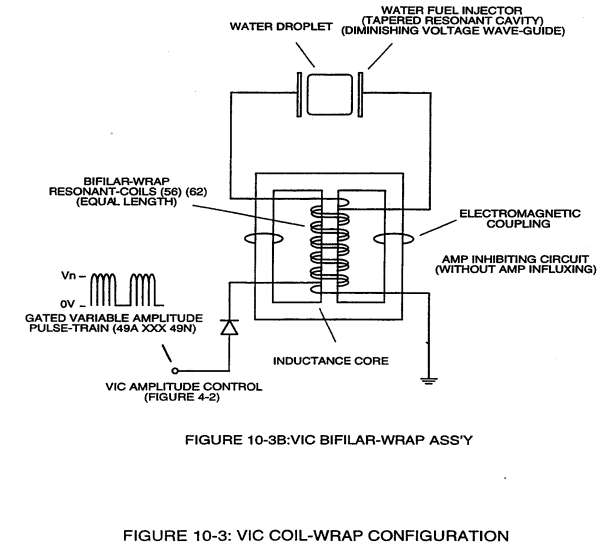
… ond applied voltage input since the "Distributed Capacitance" (C1a xxx C1n - C2a xxx C2n) / "Distributed Inductance" (FL1a xxx FL1n - FL2a xxx FL2n) of said "bifilar" wrapped coils (Figure 7-3) as to (990) of Figure (10-3) encourages the compounding effect (increasing magnetic field-strength during each pulsing cycle) of electromagnetic field-strength (Rp1a xxx Rp1n - Rp2a xxx Rp2n) (mutual induction) …
How it is written
- (990) 4×
Drawings 3
-
(990) of Figure (10-3) · Propagating Electrical Stress
-
voltage intensifier circuit (990) of Figure (10-3) · VIC Switchover Circuit
-
Figure (10-3) · Voltage to Amp Differential Ratio
Where it is named · 4
Propagating Electrical Stress 2×
-
… ond applied voltage input since the "Distributed Capacitance" (C1a xxx C1n - C2a xxx C2n) / "Distributed Inductance" (FL1a xxx FL1n - FL2a xxx FL2n) of said "bifilar" wrapped coils (Figure 7-3) as to (990) of Figure (10-3) encourages the compounding effect (increasing magnetic field-strength during each pulsing cycle) of electromagnetic field-strength (Rp1a xxx Rp1n - Rp2a xxx Rp2n) (mutual induction) …
-
(990) of Figure (10-3)
VIC Switchover Circuit 2×
-
voltage intensifier circuit (990)
… e electrical intensity on both stationary voltage fields (952/953) are similar due to the fact that both primary coil (957) and secondary coil (958) comprising and forming voltage intensifier circuit (990) of Figure (10-3) are together bifilar wrapped in equal length.
-
voltage intensifier circuit (990)
voltage intensifier circuit (990) of Figure (10-3)