(957)
Primary Input Coil
Also written primary coil
Where it is first named
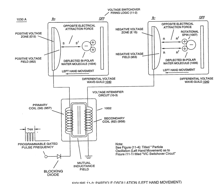
When incoming programmable gated pulse-frequency waveform (T4A) of Figure (11-2) electrically energizes primary input coil (957) of Figure (11-3) to produce positive voltage field (952) across voltage zone (EI3), the bipolar electrical charged water molecule having a negative charged oxygen atom is deflected and moved toward s …
How it is written
- (957) 3×
- (957/56) 1× with (56) Resonant Charging Choke
- (957/56 - 958/62) 1× with (56) Resonant Charging Choke, (958) Negative Voltage Field, (62) Resonant Charging Chokes
- (957/958) 1× with (958) Negative Voltage Field
Drawings 6
-
(1030) of figure (11-3) · Voltage Flexing Process
-
(990) of Figure (10-3) · Propagating Electrical Stress
-
The programmable pulse-frequency (49a xxx 49n) of Figure (10-1) input is simply adjusted to tune-in to the dielectric property of the Water Molecule. · Propagating Electrical Stress
-
Figure (10-3) · Voltage to Amp Differential Ratio
-
voltage intensifier circuit (990) of Figure (10-3) · VIC Switchover Circuit
-
(970) of Figure (10-1) · VIC Switchover Circuit
Where it is named · 6
VIC Switchover Circuit 6×
-
primary input coil (957)
When incoming programmable gated pulse-frequency waveform (T4A) of Figure (11-2) electrically energizes primary input coil (957) of Figure (11-3) to produce positive voltage field (952) across voltage zone (EI3), the bipolar electrical charged water molecule having a negative charged oxygen atom is deflected and moved toward s …
-
primary input coil (957)
primary input coil (957) of Figure (11-3)
-
primary coil (957)
… cle masses of the water molecule (s) are basically identical in volume-size and the electrical intensity on both stationary voltage fields (952/953) are similar due to the fact that both primary coil (957) and secondary coil (958) comprising and forming voltage intensifier circuit (990) of Figure (10-3) are together bifilar wrapped in equal length.
-
The simultaneous formation of both the positive voltage field (952) and the negative voltage field (953) is simply accomplished by the mutual electromagnetic inductance coupling field that is produced between the two bifilar wrapped coils (957/56 - 958/62) when the primary coil (957/56) is electrically energized by incoming voltage pulse train (T4a xxx T4n), as so illustrated in (970) of Figure (10-1).
-
primary coil (957/56)
The simultaneous formation of both the positive voltage field (952) and the negative voltage field (953) is simply accomplished by the mutual electromagnetic inductance coupling field that is produced between the two bifilar wrapped coils (957/56 - 958/62) when the primary coil (957/56) is electrically energized by incoming voltage pulse train (T4a xxx T4n), as so illustrated in (970) of Figure (10-1).
-
Voltage intensity (952/953) is, therefore, directly determined by the number of turns of each coil (957/958) as to the applied voltage amplitude of incoming pulse-wave ( ... xxx Vn) (1060) of Figure (11-2c).