Figure (10-2)
Figure (10-2)
How it is written
- (10-2) 7×
Drawings 1
-
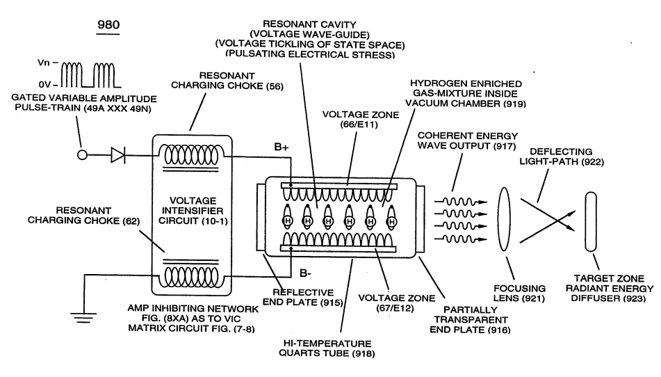
... emitting Coherent Energy Wave-Form (917), as so illustrated in (980) of Figure (10-2). · Optical Thermal Lens
On this figure 11
- 917 Radiant-Energy
- 919 Spontaneous Emission Of Coherent Energy
- 980 Optical Thermal Lens
- Ers Emitted Energy Radiation Wavelets
- Es Voltage Gate-Pulse
- Fd Flex-Density
- RU Electrical Stress
- RU' Electrical Stress
- ST Electrical Stress
- ST' Electrical Stress
- Vgp Opposite Voltage Potential
Where it is named · 7
Optical Thermal Lens 2×
Quartz Tube Configuration & Operational Parameters 1×
-
... thereby, establishing functional parameters of Optical Thermal Lens (980) of Figure (10-2) when Voltage Intensifier Circuit (VIC Circuit) (10-1) is electrically connected to Voltage Zones (ER) (66/Ell-67/E12).
A Technique Called "Easer" 4×
-
Energy Priming Stage (500) of Figure (5-1) is, now, activated and performed when the hydrogen atom (s) is exposed to applied Voltage-Sync Gate Pulse (Vgp) by which Electrical Voltage Attraction Forces (Electrical Stress) (RU-RU' - ST-ST') causes "Particle Oscillation" of the hydrogen atom (s) to emit radiant energy (Ers) (919), as so illustrated in (980) of Figure (10-2) as to (500) of Figure (5-1).
-
(980) of Figure (10-2)
-
The greater the electrical stress force (xxxEsfn) per (-) Voltage Gate-Pulse (Esf- V gpa xxx Esf- V gpn) applied, the greater amount of Flex-Density (xxx Fdn) of electromagnetic radiant energy (917 a xxx 917) of Figure (10-2) per cm3 occurs.