(18)
Variable Unipolar Pulse
Where it is first named
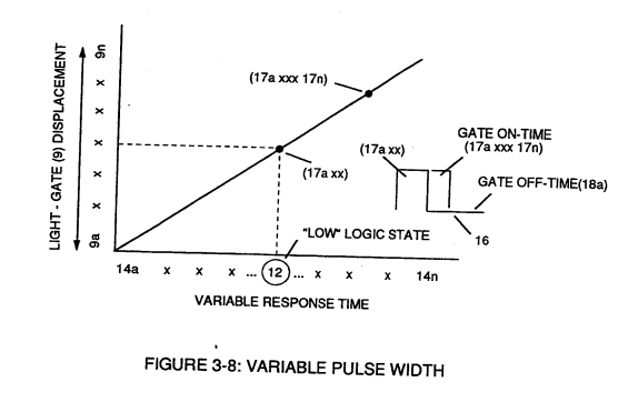
Circuit (30) electronically and automatically scans output signal-array (14axxx ... 12 ... xx14n) (15) until circuit (30) locates, momentarily registers, and translates response-time (14a xxx ... 12) into a variable unipolar pulse (17/18) of Figure (3-8).
How it is written
- (18) 9×
- (17/18) 1× with (17) Pulse width
Drawings 39
-
Copyright © 1983 in U.S.A. By Stanley A. Meyer © under UCC 1987 By Stanley A. Meyer U.S. and Foreign Patents Pending · WFC 417 — WFC 417
-
I, is the forward current through LED cluster-Array; Vo¢ is volts applied (typically 5 volts). Stanley A. Meyer Page 14 of 28 · WFC 417 — WFC 417
-
Copyright © 1983 by Stanley A. Meyer Stanley A. Meyer Page15 of 28_ · WFC 417 — WFC 417
-
Figure (1-5) · LC Voltage
-
Carries this number · Laser Interaction
-
Carries this number · Acceleration Control Circuit (30)
-
Figure (3-13) · Acceleration Control Circuit (30)
-
Figure (3-13) · Acceleration Control Circuit (30)
-
Figure (3-18) · Cell Driver Circuit (90)
-
Carries this number · WFC 422DA - Illustrations
-
Carries this number · WFC 422DA - Illustrations
-
Carries this number · Electronic Circuit Design
-
Carries this number · Electronic Circuit Design
-
Carries this number · Electronic Circuit Design
-
Carries this number · Electronic Circuit Design
-
Carries this number · Electronic Circuit Design
-
Carries this number · Electronic Circuit Design
-
Carries this number · Electronic Circuit Design
-
Carries this number · Electronic Circuit Design
-
Carries this number · Electronic Circuit Design
-
Carries this number · Electronic Circuit Design
-
Carries this number · Differential Air-Gas Inlet Control
-
Carries this number · Water Fuel Injector (Taper Resonant Cavity Chamber)
-
(220) of Figure (18) · Water Fuel Injector (Taper Resonant Cavity Chamber)
-
(520) of Figure (4-3) · Funneling Effect
-
thereby, attenuating voltage amplitude (voltage intensity) beyond Secondary Coil (53) voltage levels (71), as illustrated in (220) of Figure (18). · Funneling Effect
-
…satisfying Energy Gas Detonation Equation. (Eq 18) · Water Fuel Injection System - Page 3
-
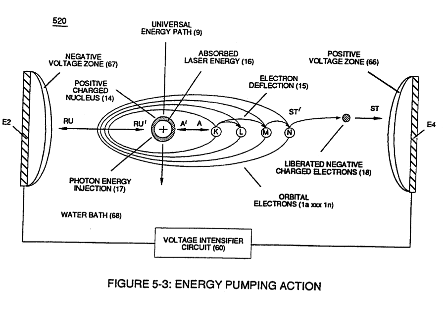
Carries this number · Energy Pumping Action
-
(520) in Figure (5-3) · Resonant Propagation
-
(520) of Figure (5-3) · In Application of Usage
-
(520) of Figure (5-3) · Solar Energy Actuator
-
Carries this number · Illustrations
-
Hydrogen Fracturing Process (520) of Figure (5-3) · Voltage Intensifier Coil-Assembly
-
(520) of Figure (5-3) · 8-2 - Traveling Voltage Wave-Guides
-
Energy Pumping Action (520) of Figure (5-3) · WFC Development Objectives
-
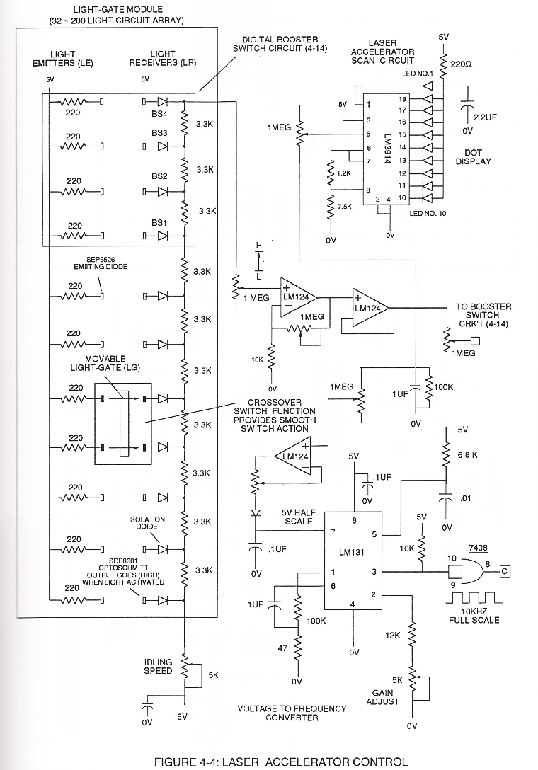
Toggling action at full-scale deflection (13a xxx 13n) occurs in the range of (10) kHz or above and thus, allows instant response to driver's acceleration demands. · Acceleration Control Circuit (30)
-
3-8 Multi-Coil Spool · Voltage Intensifier Coil Assembly
-
The figure it sits on · Electronic Circuit Design
-
Figure (4-4) · Water Fuel Injection System - Page 1
Where it is named · 10
Acceleration Control Circuit (30) 1×
-
variable unipolar pulse (17/18)
Circuit (30) electronically and automatically scans output signal-array (14axxx ... 12 ... xx14n) (15) until circuit (30) locates, momentarily registers, and translates response-time (14a xxx ... 12) into a variable unipolar pulse (17/18) of Figure (3-8).
Water Fuel Injector (Taper Resonant Cavity Chamber) 6×
-
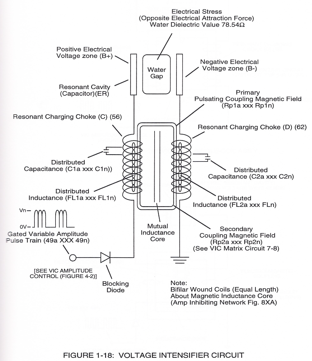
Voltage Intensifier Circuit (220) of Figure (18) allows Electrical-Stress variation (SS' = RR' / TT' = UU') since voltage Intensifier Circuit (220) inhibits electron-flow (amp restriction) into voltage triggering process (210) of Figure (17) as to (100) of Figure (6).
-
Incoming pulse-train (210a xxx 210n) is adjusted to "tune-in" to the Dielectric Properties of Water (47) which allows Resonant Action (see WFC Memo 424, once again) to occur since the Dielectric property of water (78.54 value) becomes a integral part of Electronic Circuit (110) of Figure (7) as to (220) of Figure (18)
-
(220) of Figure (18)
-
... forming a capacitor (E7 / E8) in series with Resonant Charging Chokes (56/57) placed on opposite sides of Resonant Cavity Zone (35) as to Figure (7) and (8) . . . forming a Resonant Pulsing Circuit (110) of Figure (7) with step-up Pulsing Transformer (33/36), as shown in (220) of Figure (18).
-
Adjusting Pulse-train (210a xxx 210n) in such a way as to allow pulse off-time (T2) to be synchronized with collapsing and re-formation of electromagnetic field coupling across pulsing transformer (52/53) to produce unipolar pulse frequency (T1a xxx T1n), as illustrated in (220) of Figure (18) as to Figure (17).
-
(220) of Figure (18)
Funneling Effect 3×
-
Enhancement of the operational parameters of Hydrogen Fracturing Process (100) of Figure (6) is further exemplified when incoming Resonant voltage-wave (58) of Figure (18) electrically transmitted across Resonant Cavity Zone (35) during water injection cycle...
-
thereby establishing Voltage Level Logic Function (260) which is electronically transferable in sequential order (260a xxx 260n) by Laser Acceleration Control Circuit (4-4) of (220) of Figure (18).
-
thereby, attenuating voltage amplitude (voltage intensity) beyond Secondary Coil (53) voltage levels (71), as illustrated in (220) of Figure (18).