patent · US6209493
Internal combustion engine kit with electrolysis cell
3 April 2001
Page 1 — bibliographic record
(12) United States Patent (10) Patent No.: US 6,209,493 B1 ROSS (45) Date of Patent: Apr. 3, 2001
(54) INTERNAL COMBUSTION ENGINE KIT 5,452,688 9/1995 Rose ......................................... 123/3 WITH ELECTROLYSIS CELL 5,711,865 1/1998 Caesar .................................. 205/628 (75) Inventor: Bill Ross, Newmarket (CA) FOREIGN PATENT DOCUMENTS
(73) Assignee: Global Tech Environmental Products sk -
Inc., Aurora (CA) cited by examiner - 0 Primary Examiner Tony M. Argenbright (*) Notice: Subject to any disclaimer, the term of this ASSistant Examiner-Katrina B. Harris patent is extended or adjusted under 35 (74) Attorney, Agent, or Firm- Piasetzki & Nenniger
(21) Appl. No.: 09/361,138 An electrolysis cell and internal combustion engine kit (22) Filed: Jul. 27, 1999 including an electrolysis cell is disclosed. The cell includes a Sealed plastic body having an inlet and an outlet. The (51) Int. Cl. ............................................... FO2B 43/08 plastic body includes a first terminal located at the top of the (52) U.S. Cl. ... 123/3; 204/242; 204/267; body, a Second terminal located adjacent to the first terminal 205/688; 123/DIG. 12 and insulated conductors associated with each terminal (58) Field of Search .................................. 123/DIG. 12, 3 extending through the body and towards the bottom end thereof. Each terminal ends in a respective anode and (56) References Cited cathode which are operatively connected to the terminals. The anode and cathode are spaced apart from one another
3,939,806 * 2/1976 Bradley .................................... 123/3 the body, and a current provided acroSS the electrodes, water 4,085,709 * 4/1978 Tangri ....... ... 123/1 A is caused to decompose into hydrogen and oxygen. These 4,090,485 * 5/1978 La Creta ....... ... 123/133 combustible gases are then passed into the internal combus 4,271,793 * 6/1981 Valdespino ... ... 123/3 tion engine to increase the efficiency and power thereof. In 4,368,696 * 1/1983 Reinhardt .......... ... 123/3 one embodiment a reservoir is provided to ensure that the 4,369,737 1/1983 Sanders et al. ... ... 123/3 level is maintained in the cell. Safety features include a low 4,620,915 11/1986 Ohlin ................ ... 204/284 level Sensor Switch and low level shut off, a temperature 5,082.544 * 1/1992 Willey et al. ......... ... 204/270 s 5,105,773 4/1992 Cunningham et al. .................. 123/3 sensor and high temperature cut off, and a pressure Sensor 5,119,768 * 6/1992 Russell .................. 123/1A and high pressure cut off.
5,143,025 9/1992 Munday ................................... 123/3 5,231,954 8/1993 Stowe ....................................... 123/3 10 Claims, 8 Drawing Sheets
Page 2
Drawing sheet — no readable text.
Page 3
Drawing sheet — no readable text.
Page 4
Drawing sheet — no readable text.
Page 5
Drawing sheet — no readable text.
Page 6
Drawing sheet — no readable text.
Page 7
Drawing sheet — no readable text.
Page 8
Drawing sheet — no readable text.
Page 9
Drawing sheet — no readable text.
Page 10
INTERNAL COMBUSTION ENGINE KIT The preferred form of the electrolysis chamber taught by WITH ELECTROLYSIS CELL this patent is a plastic walled chamber, into which the terminals are Sealed. The terminals project from the lower
FIELD OF THE INVENTION side of the plastic shell of the electrolysis cell itself. This invention relates to the general field of combustion The unit comes on when the motor is turned on and the engines, and more particularly, to combustion engines of the cell, and in particular the terminals, tend to heat up consid type that use conventional hydrocarbon fuels Such as gaso erably. Under the continual heating and cooling cycling the line or diesel fuel, natural gas and propane in combination Seals around terminals can crack leading to a loSS of Seal with fuel additives Such as hydrogen and oxygen. Most integrity and leaks. This requires more frequent replenish particularly, this invention relates to an electrolysis cell ment of the electrolyte, and a loSS of function. In addition, capable of producing hydrogen and oxygen for use in an the electrodes of this prior device extend about two thirds to internal combustion engine as a fuel additive for improving three quarters of the way to the top of the device. Thus, there performance and reducing pollution from the internal com is not much free board of Solution above the top of the bustion engine. electrode which is disadvantageous. After only a short 15 period of operation, parts of the electrodes become exposed,
BACKGROUND OF THE INVENTION creating a need for addition of distilled water. This requires Modern gasoline and diesel engines are much more frequent replenishment of the fluid, which is awkward and efficient and less polluting than Similar engines of even a few time consuming. Further there is always a risk, when the years ago. However, due to the increased number of vehicles electrodes are exposed, of a Spark causing an explosion of in use, levels of air pollution continue to rise even in light the highly combustible gases in the unit. of more efficient and clean running vehicles. Therefore, In addition, the patent teaches that the gases produced in there has been increasing pressure to develop vehicles which the electrolysis chamber be introduced directly into the PVC have lower emissions, and thus are leSS polluting than Vacuum line used for circulating crank case gases to the conventional automotive technology permits. 25 intake manifold So that oxygen and hydrogen generated in
For example, under certain government “Clean Air” the electrolysis cell are withdrawn by the vacuum effect in legislation, a certain number of vehicles are required to be the vacuum line.
emission free. This legislation has put pressure on OEM’s to This has been found to be problematic. The introduction develop alternate fuel technologies including electric cars of the gases into the PVC vacuum line creates considerable and Vans, natural gas and propane fuelled vehicles, hydrogen problems for modem engines. Such engines typically cell vehicles and the like. While a number of these tech include Sensors for monitoring input air quality (the So nologies are promising, Some are still a long way from called “MAP" or mass air pressure sensors) which provide commercial implementation, and others appear to have output to a microprocessor which can for example adjust the reached the limit of present design capabilities without fuel input to the engine accordingly. Additional Sensors yielding a consumer acceptable product. Therefore, attention 35 monitor the combustion outputs. Introducing these addi has refocused on conventional gas and diesel burning tional gases into the PVC means that they are put in engines, to try to develop a more pollution free and efficient downstream of the MAP sensors which creates an combustion System. imbalance, fooling the microprocessor and causing the In the past, it has been discovered that the use of hydrogen engine to misfire and behave poorly. Thus, in Some cases, and oxygen as a fuel additive increases the efficiency of an 40 introduction of the gases creates a worse polluting engine. internal combustion engine and reduces pollution consider Considerable adjustment of the microprocessor controller is ably. Both advantages appear to be the byproduct of faster required to make resolve this issue, which increases instal flame Speed that is as much as 9 times that of gasoline, lation and Servicing costs.
resulting in more complete combustion of the fuel in the SUMMARY OF THE INVENTION combustion chamber, with the resultant reduction in Soot 45 (semi-bumt hydrocarbons) and other pollutants Such as What is required is a simple and inexpensive System nitrous oxide, carbon monoxide, and an increase in output which overcomes the problems associated with the prior art energy for a greater fuel efficiency and horsepower. devices. Most particularly, this System should include a U.S. Pat. No. 5,231,954, which issued on Aug. 3, 1993, Sealed chamber, to prevent the electrolytic Solution from teaches an electrolysis cell for use in connection with a 50 being lost to effects other than electrolysis. In addition, the combustion engine for generating hydrogen and oxygen device should include electrodes which are located well gases which are added to the fuel delivery System as a beneath the surface of the electrolytic solution, to allow the Supplement to the gasoline or other hydrocarbons burned electrolytic Solution to be used up without exposing the therein. While this patent proposes an electrolysis unit which electrodes. Further the System should include an automatic is relatively simple and easy to install, this prior device has 55 shut off Switch to cause the unit to Stop in the event the liquid a number of problems which require considerable mainte level gets low enough to expose the electrodes. In addition, nance and lead to higher costs associated with installing and most preferably the device will conduct electrolysis in a low using the device. resistance electrolysis fluid, permitting it to operate at rela This patent teaches a low concentration of electrolyte, by tively low temperatures to prevent damaging heating and weight, which is created by pre-mixing and pre-charging a 60 cooling cycles which can impair Seal integrity. AS well the concentrate for 24 hours. This results in a higher resistance device should have any joints or openings in the Sealed electrolysis cell which can be connected directly to a con chamberformed above the highest liquid level in the cham ventional vehicle battery. In the context of consumer ber. In this manner, even if a leak develops, the leak will applications, it is too awkward to do this pre-charging and Simply allow additional air into the electrolysis chamber mixing. In addition, Since the resistance of the Solution is 65 rather than leaking out electrolytic Solution. Lastly, the relatively high, a high amount of heat is created in the cell System should preferably compensate for loss of liquid water during use, which can be problematic. to decomposition to prevent over concentration of the
Page 11
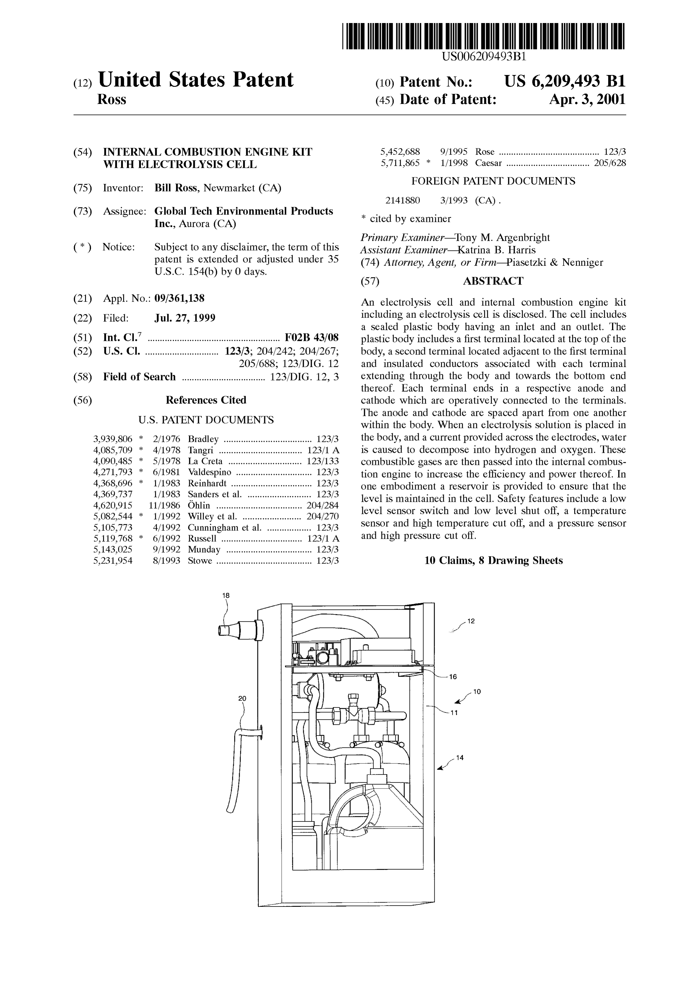
Solution, which can lead to a higher resistance cell and preSSure Switch that are located external to the box enclosure excessive heat generation. 11. These elements are discussed further below. The dimen Accordingly, there is provided an electrolysis cell accord sions of the preferred embodiment of the box enclosure 11 ing to the present invention comprising: are about 12 inches by 12 inches by 24 inches. This size is a Sealed plastic body; small enough to permit the assembled kit 10 to be conve niently attached, as an add-on, to one or more locations in or an outlet vent on the body; on a typical commercial vehicle. In a large tractor-trailer an inlet vent on the body; type vehicle, with an engine Size of about 7-15 liters, the a first terminal located at a top of Said body; box enclosure 11 may be conveniently attached to the bracket that holds the fuel tanks, outside the engine com a Second terminal located adjacent to Said first terminal; partment. In that case the output hose 20 will be run to the an insulated conductor associated with each terminal engine air intake. In Some cases, this distance will be about extending through Said body and towards a bottom end 15 feet.
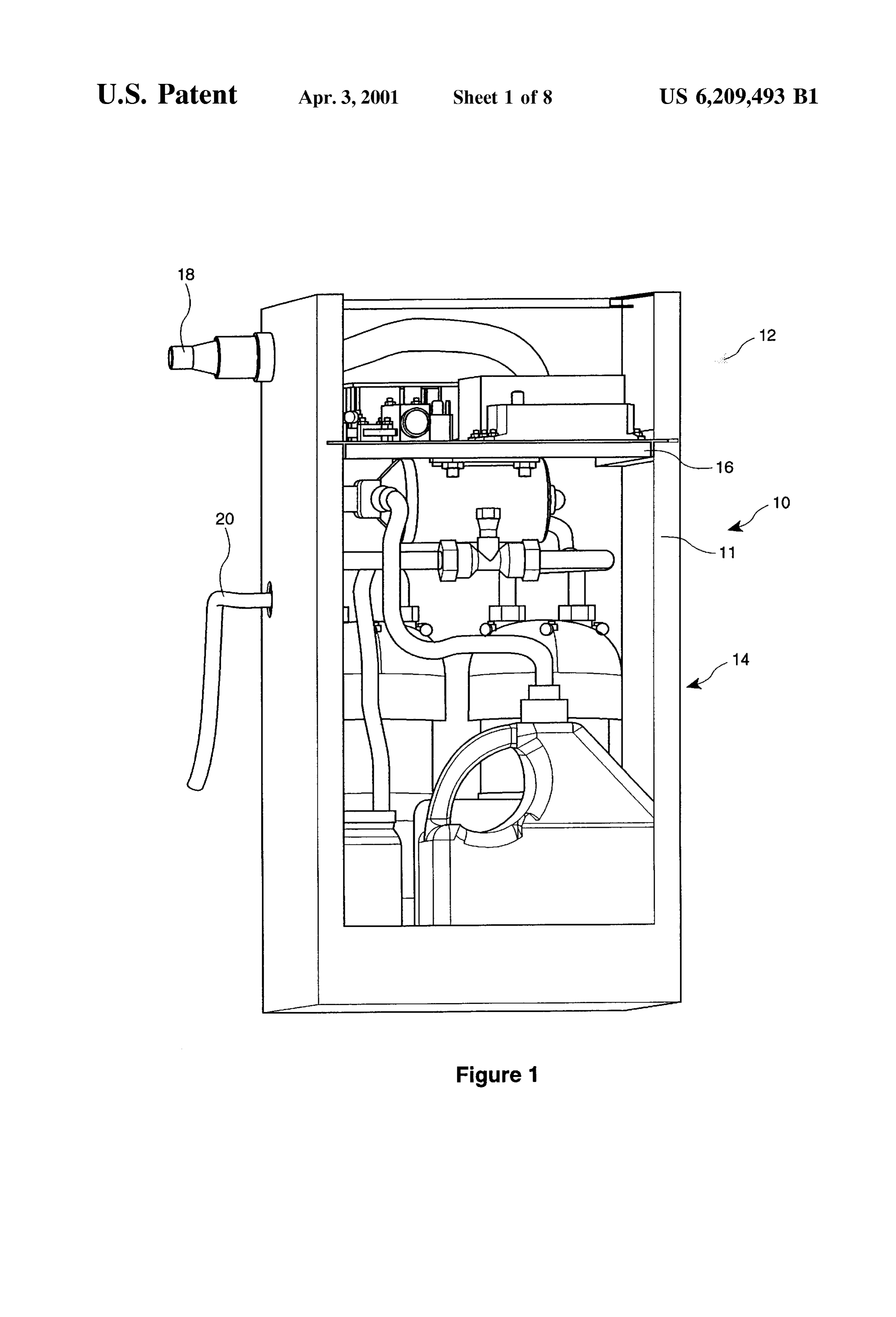
thereof; FIG. 2 is a detailed view of the elements of the electrical an anode operatively connected to one of Said terminals, 15 section 12, resting on the base or shelf 16. The wiring and harneSS 18 carries electrical power and communication a cathode associated with the other of Said terminals, Said Signals into and out of the assembled kit 10. Included among anode and Said cathode being Spaced apart from one the electrical components mounted on the shelf 16 are a C.P.U. 22, cell power supply 24, auto-refill electronics another within said body. circuit 26, and relay 28.
BRIEF DESCRIPTION OF THE DRAWINGS The C.P.U. 22 may be any common programmable con trol device, Such as a microprocessor or programmable logic
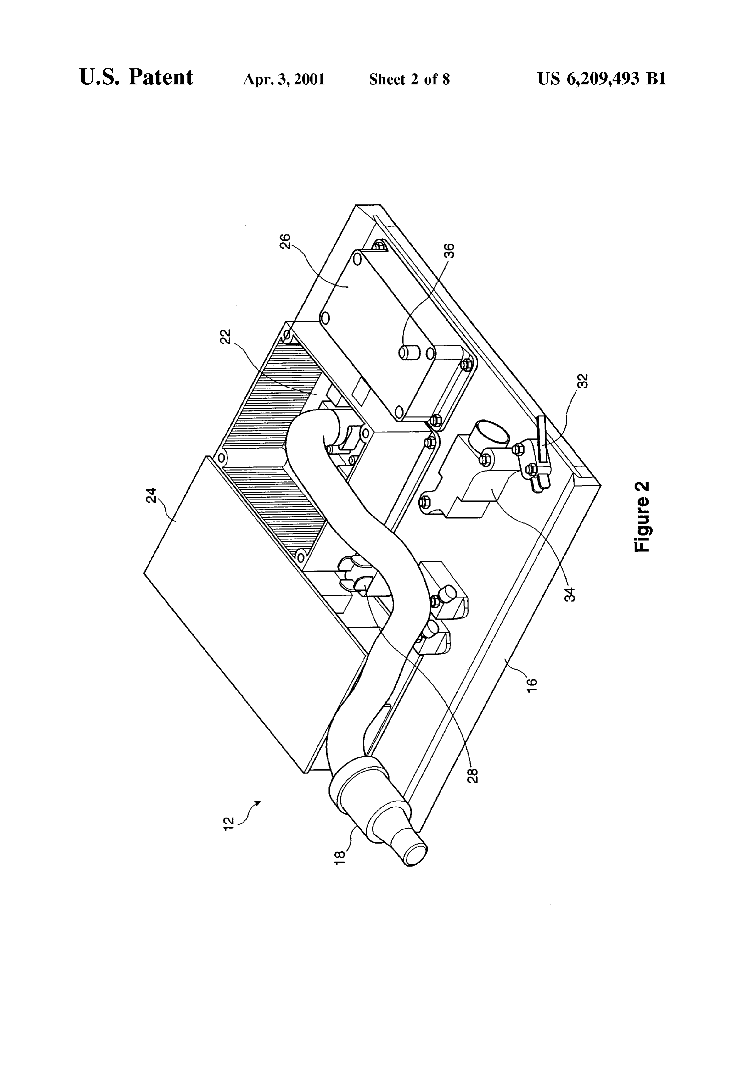
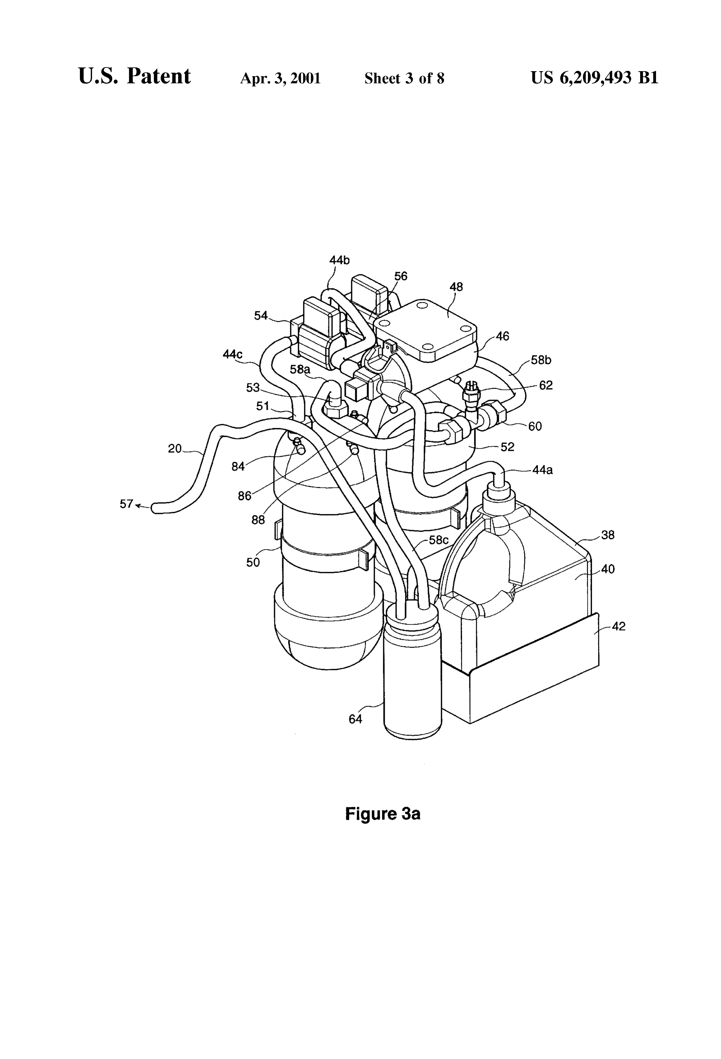
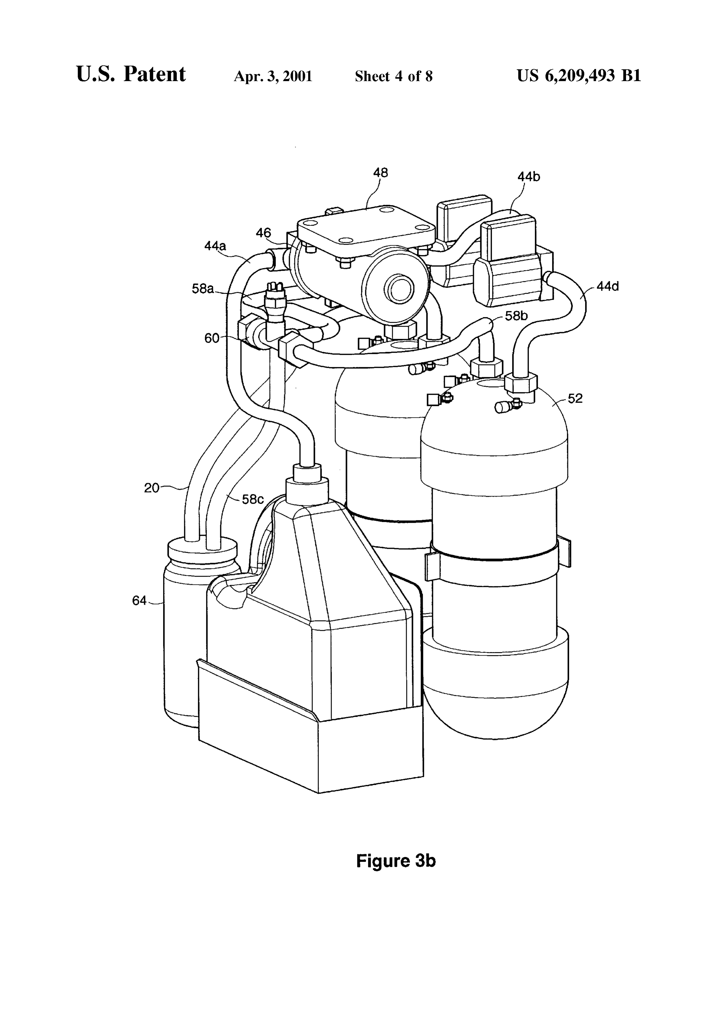
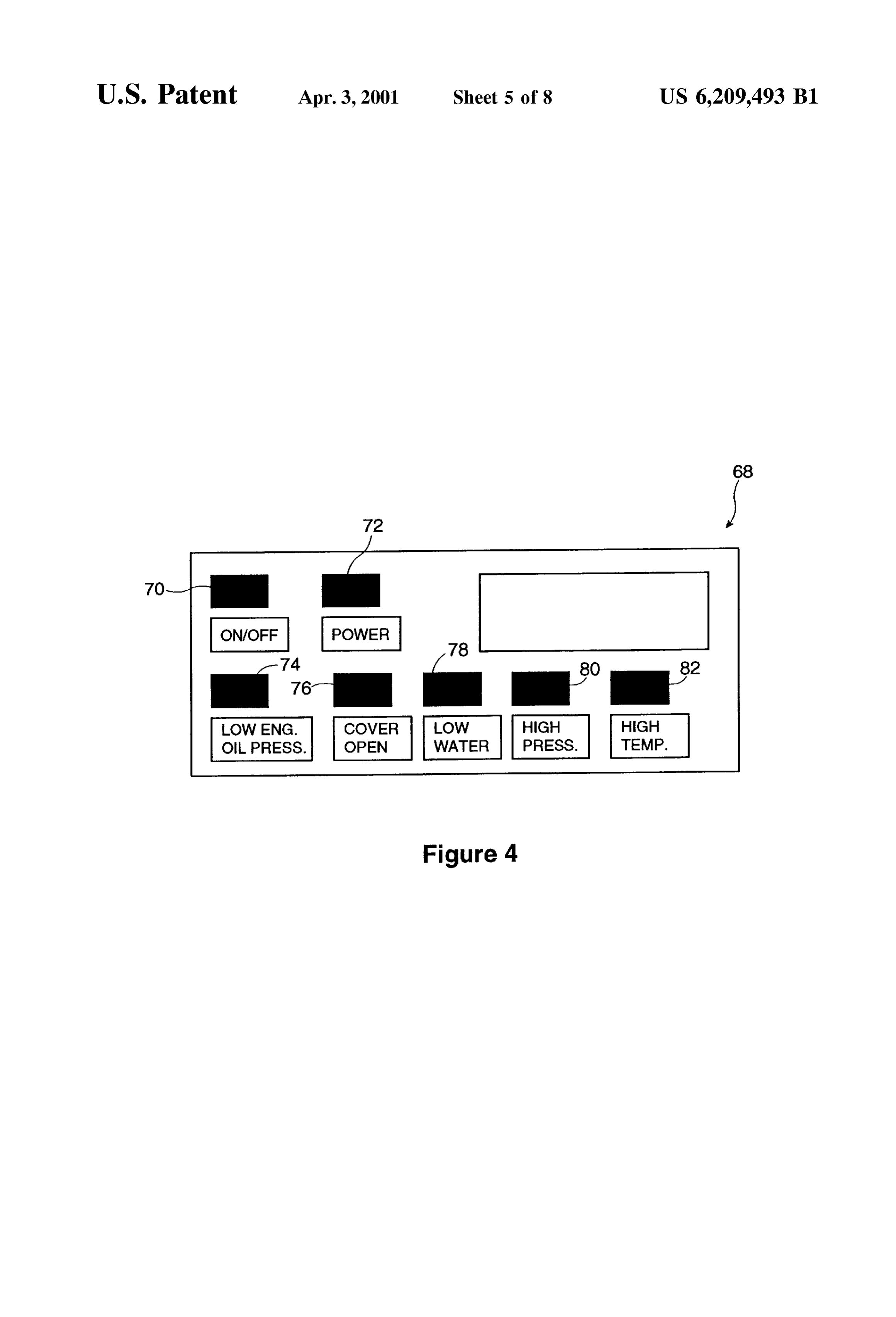
Reference will now be made, by way of example only, to controller (PLC). In the preferred embodiment of the preferred embodiments of the invention as illustrated in the invention, a PLC is preferred because of its low cost and attached figures. relatively simple and embedded programming Scheme. The FIG. 1 is a perspective view of a kit of components, 25 PLC is typically a Single chip device with a plurality of pins, most of which connect with one of the various Switches, including an electrical Section and a fluid Section, assembled Sensors, according to the present invention; or display units that comprise Some of the compo nents of the assembled kit 10, as further discussed below.
FIG. 2 is a perspective view of the electrical section of Among the electrical Signals carried in the wiring harneSS FIG. 1; 18 is an input power line from the vehicle battery. This line FIG. 3a is a perspective view of the fluid section of FIG. Supplies power to the C.P.U. and other digital electronic 1; devices, and also to the cell power Supply 24. The cell power FIG. 3b is the same view as FIG. 3a, shown at a different Supply 24 is a passive device that contains a power condi angle, tioning means in the form of a DC-DC converter to power FIG. 4 shows the operator panel; 35 the electrolysis process. This direct current (DC) output is at a reduced Voltage and Stepped-up current from the input
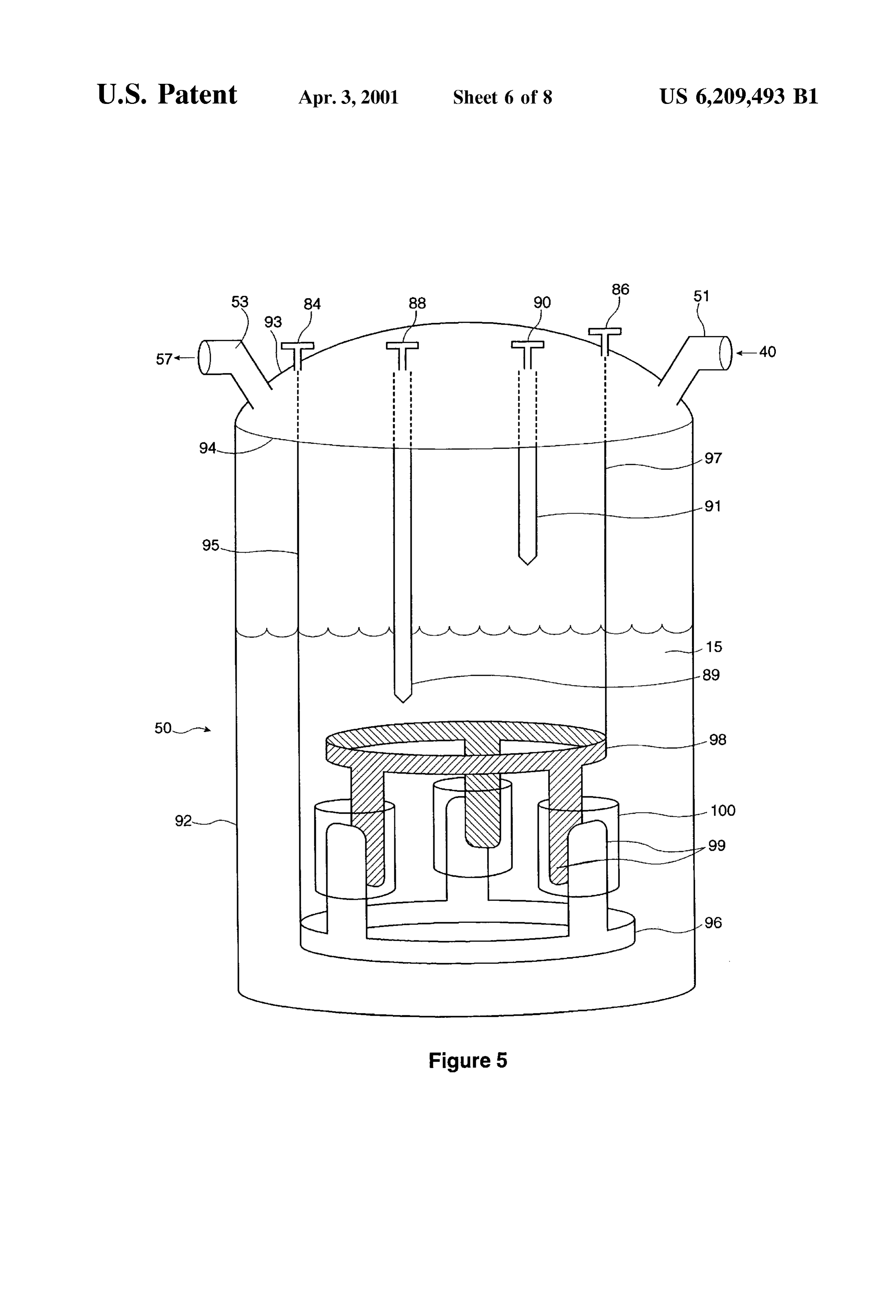
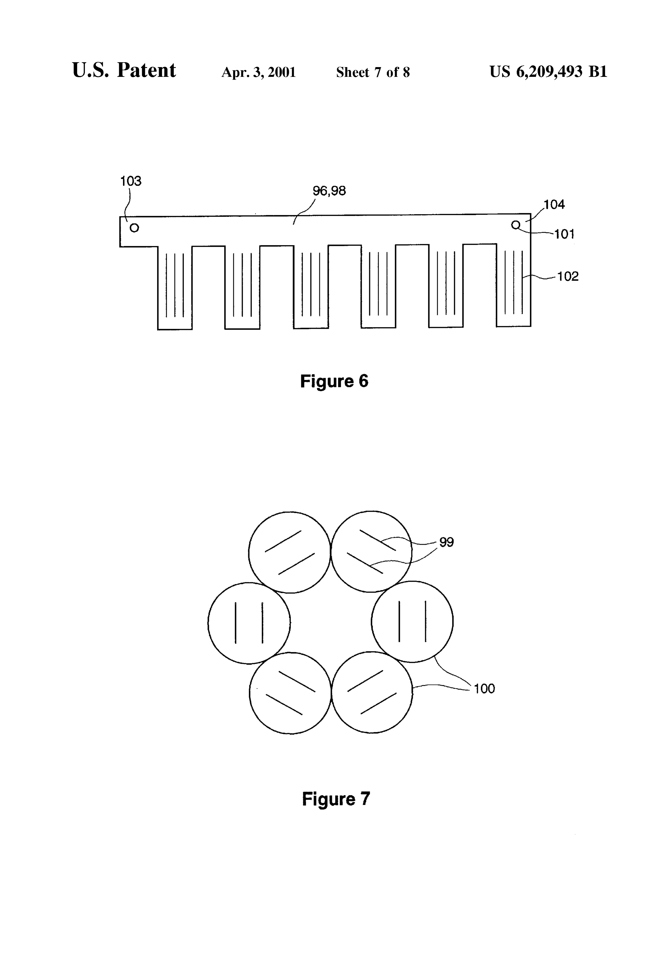
FIG. 5 is an overview of the elements of the electrolysis vehicle cell; battery power, and typically maintains a current on FIG. 6 is a schematic view of the electrode according to connectionofbetween the order 23–26 amps. The relay 28 opens or closes the the vehicle battery and the cell power the present invention; 40 supply 24, under the control of the C.P.U. When the con FIG. 7 is a plan view of the anode and cathode fingers, nection is open the cell power Supply 24 is disabled and the enclosed by tube-shaped isolators, and electrolysis proceSS is shut down. The auto-refill electronics FIG. 8 is an overview of the elements of the moisture trap. circuit 26 is a separate circuit maintained in its own housing DETAILED DESCRIPTION OF THE in the preferred embodiment. It can be appreciated however 45 that this circuitry could be incorporated into the C.P.U. 22 if
FIG. 1 shows a perspective view of a kit of components The electrical section 12 also includes a number of for providing combustion products to an internal combus Switches and Sensors, including a temperature Sensor 30, tion engine. The assembled kit is generally indicated with cover Switch 32, inertia Switch 34, and manual refill Switch reference numeral 10, and comprises an electrical Section 50 36. The temperature Sensor may be a simple thermistor, and 12, shown on top, for mostly electrical components, and a in the preferred embodiment is Set to activate upon the fluid section 14, shown on bottom, for mostly electrolysis ambient temperature in the electrical Section 12 rising above and fluid handling components, all housed in a box enclo about 80 degrees Celsius. The box enclosure 11 also Sure 11. An internal shelf 16 divides the two sections and includes a removable cover, not shown, to permit access to Supports the electrical Section 12. It can be appreciated that 55 the components of the assembled kit 10. The cover Switch 32 other configurations of the assembled kit of components are opens if the cover is not attached or improperly closed. The possible, in addition to the rectangular box shown, as long inertia Switch 34 responds with an open Signal if the Spatial as they fulfill the function of housing the kit of components orientation of the assembled kit 10 is disturbed. This could in a convenient enclosure. occur, for example, if the vehicle experiences a collision or FIG. 1 illustrates that the present invention may be viewed 60 other accident. The manual refill Switch 36 acts to bypass the as a “black box” with two outer connections. One connec auto-refill electronics circuit 26, So that the refill function tion is a wiring harness 18, which carries a bundle of performed by the circuit may be provided, upon manual electrical wire and cable. A Second connection is output hose intervention, in the event of a failure by the circuit. The 20, which carries generated hydrogen and oxygen gas to a temperature sensor 30, cover Switch 32, and inertia Switch vehicle internal combustion engine, not shown. For greater 65 34 connect with the C.P.U. So that, upon activation by any clarity, it may be noted that the preferred embodiment of the one of them, the C.P.U. is notified and can take appropriate present invention also includes an operator panel and oil action, generally consisting of Shutting down the device.
Page 12
S 6
The components of the fluid section 14 are shown in connects at its other end to a moisture trap 64. Finally, the FIGS. 3a and 3b. These figures both show the same elements gas flow path continues out of the moisture trap through from different perspectives. Generally, the fluid section 14 ofoutput gas hose 20.
FIGS. 3a and 3b describes two paths: a water flow path and There is a Second, preferred embodiment of the gas flow a gas flow path. path that is not directly illustrated in the drawings but that A Starting point for the water flow path is water reservoir may be readily described. In this embodiment there is no gas 38, which contains a reservoir of distilled water 40. The reservoir 38 is held in place by a water jug bracket 42. A hose 58a, T-Section 60, or gas hose 58c. Rather, the moisture trap 64 sits directly on top of the gas output of cell 50, at gas water hose connects the water reservoir to a fill pump 46 outlet 53. Gas hose 58b, emanating from the other cell, through a first Section, designated 44a. The fill pump 46 attaches near the top and Side of moisture trap 64. AS there mounts just below the shelf 16 through an attached mount is no T-Section in this embodiment, the pressure sensor 62 ing bracket or plate 48. The water hose continues beyond the would fill pump through a Second Section 44b to a T-Section, not Output be attached to the side wall of the moisture trap. gas hose 20 extends from the moisture trap 64 to the
Visible in the drawings, that splits the water hose into two engine as before. The advantages of this embodiment relate further sections, designated as 44c and 44d. Water hose 15 to improved efficiency in moisture capture and disposal, and section 44c connects with a first electrolysis cell 50 and, as are discussed below in the Section relating to the design of seen in FIG. 3b, water hose section 44d connects with a the moisture trap. Finally, it may be noted that where only Second electrolysis cell 52. These connections are made one cell is used, the first embodiment is preferred, with the through a water inlet 51 on each cell. A pair of Solenoids, preSSure Sensor attached to the moisture trap as in the Second designated as Solenoid 54 and Solenoid 56 respectively, are embodiment.
located on either side of the T-section. Each Solenoid attaches to a separate gate and acts independent of the other As noted above, there is an oil pressure Switch 66 that is not shown as part of the assembled kit 10 or in any of the
So that, when the Solenoid is in a closed position, the path is drawings.
blocked through water hose section 44c and/or 44d, as the installed onThis switch is an off-the-shelf switch that is easily case may be. The entry of water hose sections 44c and 44d 25 non-functional oilvehicle the engine by inserting it in place of a gallery plug. The oil pressure Switch 66 into cells 50 and 52, respectively, marks the other end point will generally activate upon the presence of any oil pressure, for the water flow path in the fluid section 14. Such as occurs upon engine Start-up. Cells 50 and 52 are sealed chambers preferably con
Structed out of a lightweight, heat resistant material. In the Also as noted, there is an operator panel that installs in the preferred embodiment a PVC based plastic is used. Also in driver cabin. This is shown generally as 68 in FIG. 4. The the preferred embodiment two cells are used to provide operator panel has an on/off Switch 70 and a corresponding better flexibility and capacity in meeting the combustion power le.d. (light emitting diode) 72. There are also five needs of large commercial vehicles. However it can be 1.e.d.S which light up when their corresponding Sensors are appreciated that a Smaller apparatus using only one cell may active. These are: low engine oil preSSure 1.e.d. 74, which also be constructed, and may be advantageously used with 35 corresponds with oil pressure Switch 66, cover open 1.e.d. Smaller vehicles Such as automobiles. The cells in the 76, which corresponds with cover Switch32, low water 1.e.d. preferred embodiment are generally cylindrical and are 78, which corresponds with a sensor to be discussed below, approximately 13 inches high, with a diameter of approxi high pressure 1.e.d. 80, which corresponds with pressure a mately 4 inches. The output capacity of a cell is directly sensor 62, and high temperature 1.e.d. 80 which corresponds related to its Volume, So in general a larger cell may be 40 with temperature sensor 30.
preferred. However, Since it is also desired to minimize the The overall system operation of the assembled kit 10 may size of the overall assembled kit 10 to ease installation, there now be described, referring to FIGS. 2, 3a, 3b, and 4. is an opposing preference to keep the cell Size Small. It is a The System is enabled by the operator, who is generally particular advantage of the present invention that, while the driver of the vehicle, pressing the on/off Switch 70 on the keeping the cell size relatively Small, it is nonetheless able 45 control panel. In the ordinary course this informs the C.P.U. to produce a useful amount of combustible gas. The discus 22 to close the relay connecting the vehicle battery input to Sion further below concerning the design of the internal the cell power Supply 24, and alerts the operator through the components of the cells provides further information on how power 1.e.d. 72, which lights up. The system however will this beneficial effect is achieved. There are also 4 electrical not start if any of the Switches or Sensors are activated. In terminals on each cell representing a cathode terminal 84, 50 particular, the engine must be running, So that the oil anode terminal 86, low level indicator terminal 88 and high preSSure Switch detects any level of oil pressure. The cover level indicator terminal 90. Not all of these are visible in the to the box enclosure 11 must be properly closed, or there will drawings, which are marked as appropriate. be a disabling signal from the cover Switch 32. The other The flow path of gas 57 through fluid section 14 may be Sensors must also be Satisfied, but are leSS likely to be a described as follows. In one embodiment of the present 55 problem on Start-up. Electrolysis is the well known tech invention, each of cells 50 and 52 have a gas hose 6 nique whereby current is passed through liquid, causing it to designated 58a and 58b respectively, emanating from a gas decompose. Where the liquid is water it can be caused to outlet 53 located on each cell. Gas hoses 58a and 58b then decompose to hydrogen and oxygen. When the present attach to opposing ends of a T-Section 60. A pressure Sensor invention is in operation, the cathode terminal 84 and anode 62 is located at the central junction of the T-section 60. The 60 terminal 86 of each cell receives the high current DC input preSSure Sensor 62 is of a conventional type, and is Set to from the cell power Supply 24. The electrolysis process activate upon a pressure Setting of approximately 6 psi. The commences in each cell, and generated hydrogen and oxy gas may be optionally routed from the boost Side of the gen gas exits the gas hoses 58a and 58b, or, as described, vehicle turbocharger, in which case the pressure Sensor exits from cell 50 directly into the moisture trap 64. Gas would preferably be set to activate in a range of approxi 65 preSSure is monitored by the preSSure Sensor 62, which alerts mately 20–30 psi. The gas hose continues out of the the C.P.U. if the pressure rises above a pre-Set level, gen T-Section 60 as a single hose designated as gas hose 58c, and erally about 6 psi, or 20–30 psi if routed from a turbocharger.
Page 13
The presence of the pressure Sensor guards against a con fill pump 46 to begin pumping water out of the water dition Such as a kink or obstruction in the gas hose, which reservoir 38. The C.P.U. also signals either one or both of the could raise the preSSure to a dangerously high level. If the Solenoids 54 and 56 to open their respective gates, so that the C.P.U. receives a high pressure signal, it will light up the pumped water can flow into either or both of cells 50 and 52, high pressure 1.e.d. 80 on the operator panel and also trigger 5 as the case may be. The refilling continues until the level in the relay 28 to turn off power to the cells, stopping the the cell reaches a predetermined high level, at which point electrolysis. a signal is sent from the cell to the C.P.U. The C.P.U. then The generated gas generally retains Some moisture as a Signals the appropriate Solenoid to shut its gate So that no residue of the electrolysis process. The presence of moisture also signal theisfill further water permitted to enter the cell. The C.P.U. will pump to Stop, unless it is still waiting to is undesirable as it acts to undermine combustion efficiency. receive a high Signal from the other cell, in which case it will Accordingly, the generated gas is run through the moisture Stop the other Solenoid and the fill pump when the Second trap 64 so that moisture is removed from the gas before it high signal is received. At that point, the C.P.U. will turn off enters the output gas hose 20. It is preferred that most the low water 1.e.d. On the operator panel, and the System moisture is removed, and the present unit provides adequate will resume as before. If the cell cannot be refilled, as for results. Other configurations are also possible which may 15 example, if the water reservoir 38 is low, a high level Signal remove more or less moisture, but removing leSS moisture will not be received and the system will remain shut down. might negatively affect performance of the assembled kit. In In the preferred embodiment with cell sizes as noted, the the preferred embodiment, the moisture trap 64 is made from entire refill process takes approximately one minute. During a PVC based plastic, and is in the shape of a cylinder, about this time the operator may possibly experience a slight loSS 3 inches high and 1 inch inside diameter. The internal in power, but in most cases will likely not notice any operation of the moisture trap is discussed in greater detail performance related effect at all. In this way, it can be seen below. that the electrolysis cell and assembled kit of the present AS will be discussed, it is possible to configure the cells invention the vehicle maintain a continuous flow of combustible gas to engine, enhancing its performance. The presence
So that the hydrogen and oxygen gases are separated at 25 of various Sensors and Switches keep the System operating production. The hydrogen gas may be directed to the vehicle Safely, So that combustible gas is not being produced when engine, and the oxygen either allowed to escape or the engine is off, the vehicle is jarred in an accident, the re-directed as desired. One reason to pursue this course cover is not properly closed, pressure builds up in the gas would be to avoid confusing the MAP sensors present in hose, or when the temperature has risen to a high level. many vehicles, particularly passenger cars. These Sensors The configuration and operation of the electrolysis cells monitor and adjust the fuel/air combination to optimize and moisture trap may now be described in greater detail. combustion efficiency. Adding oxygen through electrolysis The broad elements of the electrolysis cell are shown in FIG without properly accounting for it can lead to increased 5. The cell 50 comprises a body 92 and lid 93, joined at a pollution and reduced combustion efficiency. sealed rim where the body meets the lid. There are six AS a response, the output gas from the output gas hose 20 35 input/output ports or terminals on the lid. The water inlet 51 may be preferably introduced into the engine ahead of the receives water from the water hose 44c. The combustible gas MAP sensors, for example at the air intake filter. In this way, exits the cell through the gas outlet 53, either to gas hose 58a the MAP sensors will be able to detect and compensate for or directly to the moisture trap 64. The cathode terminal 84 the extra input oxygen, So that an efficient combustion can and anode terminal 86 receive high current DC power from be maintained. This avoids the problems of unbalanced 40 the cell power Supply 24, to drive the electrolysis process. A readings, and removes the need to Substantially revise the low level terminal indicator 88 and high level terminal microprocessor combustion controls on most vehicles. Thus, indicator 90 are electrical terminals that connect to pins on rather than removing the oxygen, this embodiment relies on the C.P.U., to alert the C.P.U. to a condition of low fluid level introducing the gases upstream of the Sensors to avoid the and high fluid level respectively.
problems of the prior art. 45 The interior of the cell 50 may now be viewed. There is AS will be shown, the electrolysis proceSS depends on an electrolyte solution 15 that fills the interior up to a there being an electrolytic Solution inside the cells. The particular level. This Solution is composed of an electrolyte electrolytic Solution has a Substantial water component in solution with water. Although many different electrolytes which is used up by the electrolytic process. AS the water is may be used, good results have been achieved with distilled used up, the liquid level of Solution declines and needs to be 50 water and potassium hydroxide. The potassium hydroxide replenished. In other Systems, it would be necessaryforthe acts as an electrolyte, in a known manner, to lower the operatorto stop the vehicle and manually refill the cells. This resistance of the water and to improve the performance of is inconvenient and inefficient, and also raises the risk that the electrolytic cell. An operating range of potassium the operator may inadvertently cause damage to the device. hydroxide to water is about 15% to 45% by weight, with a The present invention avoids these problems by including a 55 preferred range being 25-35%, and 30% being the most refill process that operates automatically and in the back preferred ratio. AS is known in the art, at this level the ground. It is therefore an advantage of the present invention resistance of the Solution is the lowest, meaning that a that it extends the length of time during which the electroly minimum amount of heat is generated during electrolysis. sis cells can operate without Service by the operator. Other electrolytes may also be used such as HNO3, HSO, As will be shown in greater detail below, when the level 60 CrO and the like. Notwithstanding the low resistance of liquid reaches a pre-determined low level, a signal is sent however the production of hydrogen and oxygen is Sufficient from the cell to the C.P.U. Similar to the high pressure for the beneficial effects in combustion. In addition, the Situation described above, the C.P.U. generates a signal that concentration of potassium hydroxide noted will prevent the activates the low water 1.e.d. 78 on the operator panel, and Solution from freezing up to a temperature of about minus 70 also sends a Signal to the relay that disconnects the cell 65 degrees C.
power Supply, Shutting off the electrolytic process. Then, The low and high level indicator terminals connect to a through the auto-refill electronics 26, the C.P.U. signals the low level indicator rod 89 and high level indicator rod 91,
Page 14
respectively, inside the cell. The rods are made from 316L out since they will be blocked at either end by an electrode. stainless steel, and descend vertically from the lid. The low Not shown in the drawing are tie Strings that can be looped level indicator rod 89 is longer, and therefore descends around the electrodes and fingers to hold the elements in farther, than the high level indicator rod 91. The fluid level place. In the preferred embodiment, one tie String is tied will always be somewhere between the tip of the low level horizontally, making contact with the isolators, and two tie indicator rod 89 on the low end, and the tip of the high level Strings are tied in a vertical loop, making contact with the indicator rod 91 on the high end. two electrodes. Maintaining these elements in a tight con The cathode terminal 84 connects to an outer electrode nection is advantageous because once the lid is Sealed it is conductor rod 95 which is a vertical rod that descends not possible to open the cell to repair or reinforce a loose substantially into the cell. Similarly the anode terminal 86 electrode. FIG. 6 shows an electrode 96 or 98 stretched out connects to an inner electrode conductor rod 97 that flat. It will be appreciated that the ends 103,104 are joined, descends somewhat less Substantially into the cell. The by any conventional means Such as a Spot weld 101, to form conductor rods are made most preferably from StainleSS a circular loop. This loop is then Secured by Solder, welding, steel. Grade 316L stainless steel has found to yield suitable or the like to the ends of the conductor rods 95, 97. results, but other conductor material may also be Suitable. 15 Satisfactory results have been achieved with fingers of about Not shown on the drawing is that both conductor rods are 3% inches high, 3%.oOoinches thick, and 34 inches wide. Other Surrounded end to end by insulation, So there is no short dimensions will also provide reasonable results, provided circuiting or electrical or electrolysis interaction between the that a Sufficient Surface area of the electrodes 96, 98 is rods and the Surrounding Solution. It has been found that provided. It is reasonably important for Smooth operation of conventional shrink wrap plastic is Suitable for forming an the device to ensure that the electrodes are evenly spaced insulation layer around the conductor rods. apart. Therefore, it is preferred to use at least a few Spacers, Each conductor rod terminates in an electrode, preferably not shown, in between the electrodes 96 and 98 to make Sure formed in a ring. The outer electrode conductor rod 95 that there is an even annular gap.
terminates in an outer electrode 96, and the inner electrode FIG. 6 also show that the fingers each have three grooves conductor rod 97 terminates in an inner electrode 98. The 25 102. The grooves are cut completely through the fingers 99 electrodes, being extensions of the conductor rods, are So that two new edges are formed on each Side of the finger, constructed of the same Stainless Steel and are exposed to the for each groove. Because of the nature of the electrochemi Surrounding Solution. Each electrode also contains a plural cal reaction, gas bubbles tend to form on the edges of the ity of projecting tab extensions or fingerS 99 that project in plates. Therefore, forming a plate with a plurality of edges, a perpendicular plane. The inner electrode 98 is of smaller Such as the grooves 102 as shown, is believed to enhance the diameter than the outer electrode 96. The electrodes are production of hydrogen and oxygen gas in the cell. arranged so that a finger from the inner electrode 98 is For further clarity, FIG. 7 provides a plan view of the aligned with and inside of a corresponding finger on the isolators and the cathode/anode finger pairs, viewed on edge. outer electrode 96. Each such electrode pair is itself Sur An advantage of the above configuration of the cell of the rounded by an isolator 100. The isolators 100 act as an 35 present invention is that all of the terminals are placed on the electrical insulator. In the preferred embodiment the isola top lid, while the electrolyte Solution cannot rise above a tors are tube shaped and open at each end. The isolators are predetermined maximum set below the top lid. Unlike the generally made of standard PVC plastic tubing, about 3 prior art, where the terminals project from the Side of the inches high and 1 inch inside diameter. The preferred cell, there is never any contact between the fluid and the embodiment also uses six fingers on each electrode, 40 terminals. This avoids the problem of loss of seal integrity enclosed as six pairs within six isolators. FIG. 5 shows only and leaks that can occur when, as a result of continual three fingers on each electrode, and three finger pairs, for heating and cooling of fluid the Seals are caused to crack. clarity in Visualizing the relationship between the elements. The operation of the electrolysis cell can now be In the preferred embodiment of FIG. 5 the cathode described. With reference to FIG. 5, the electrolyte solution terminal is associated with the larger diameter outer elec 45 15 will be at a level somewhere between the lower tip of low trode 96 and the anode terminal is associated with the level indicator rod 89 and the lower tip of high level smaller diameter inner electrode 98. This assignment is indicator rod 91. The high current DC power is applied arbitrary and may be reversed without reservation. The across the cathode and anode terminals 84 and 86. The preferred embodiment also shows that the fingers 99 electrical charges are applied to the two electrodes, causing descend downward from the inner electrode 98, but are 50 electrical current to flow across the gap between each reversed and project upwards from the outer electrode 96. cathode finger and its adjacent anode finger. The electrical Again, this assignment is arbitrary in that the outer electrode current flows through the electrolyte in a conventional 96 could have fingers 99 that descend and the inner electrode manner, causing the electrolysis reaction to take place, i.e. 98 could have fingers that rise. Similarly, both electrodes the decomposition of water into hydrogen and oxygen. The could have fingers that are oriented in the same direction. It 55 hydrogen and oxygen gas form bubbles which rise to the can be appreciated as well that other arrangements may be Surface of the fluid, continue rising in the unfilled Space used instead of ring shaped electrodes. The key requirement above, and exit the gas outlet 53. The electrolysis proceSS is is that each of the anode and cathode maintain Some Sort of enhanced by concentrating the effect in finger pairs, with broad Surface area, with edges, in close proximity to each extensive edge producing grooves, and by enclosing each other So that electrolysis can proceed efficiently. 60 such pair with an isolator. The isolator has the effect of Notwithstanding the above comments, there is Some minimizing inefficient electrical contact between non benefit to retaining the ring shaped electrode and finger adjacent finger pairs. As a consequence, this configuration arrangement shown in the preferred embodiment of FIG. 5. and design of the present invention has the advantageous By arranging for the two rings to have fingers projecting in effect of reducing heat, So that more of the energy input is opposite directions, and by using a tube shaped isolator 65 directed to the desired electrolysis.
which is open at both ends, the electrodes and isolators can As the electrolysis proceeds the fluid level will decline as be kept in position easier. The isolators will be unable to slip water is decomposed. The potassium hydroxide electrolyte
Page 15
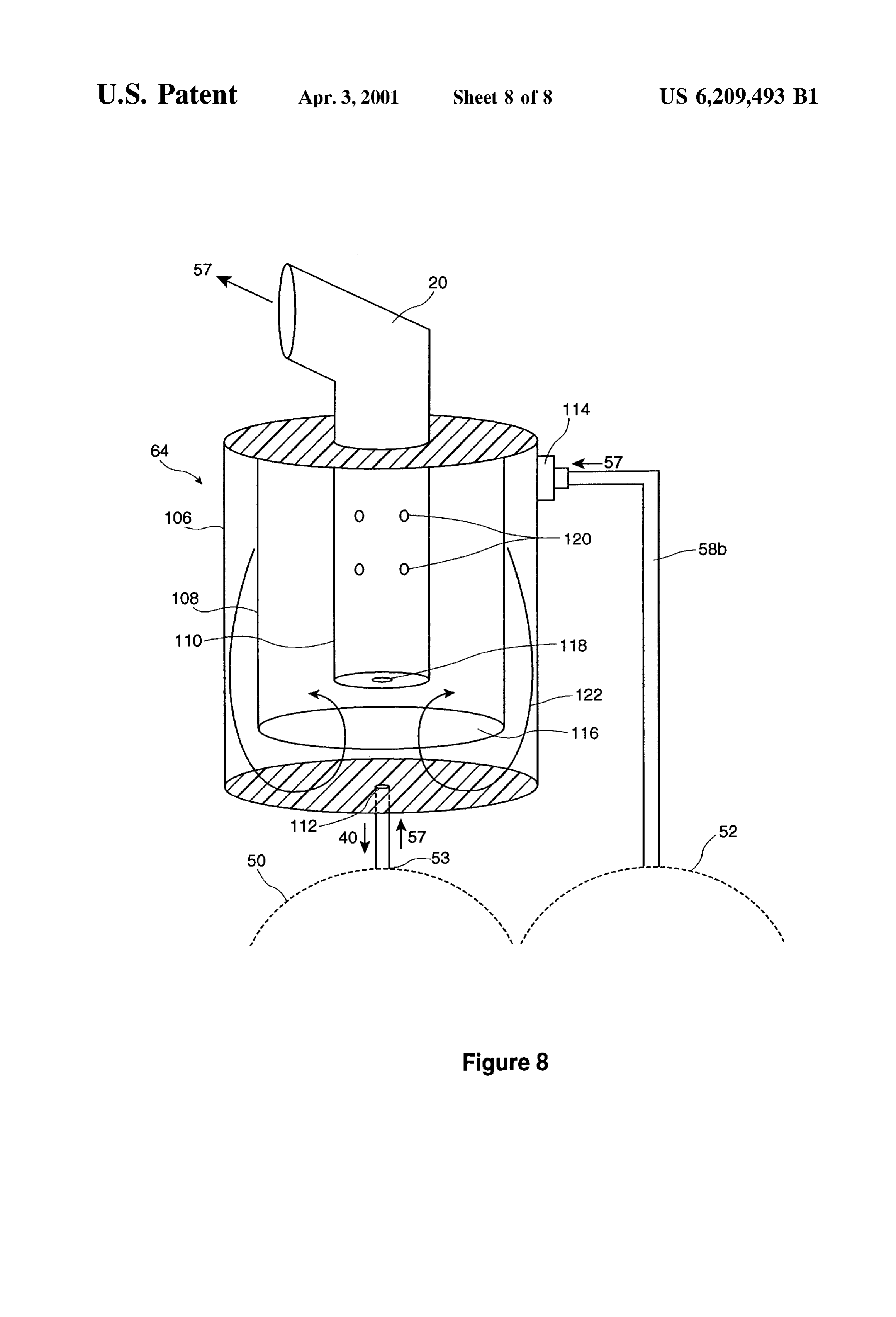
does not get used up in the reaction, and therefore does not The moisture trap 64 itself comprises three cylinders. need to be added in the usual case. However, the result is that There is a large, outer cylinder 106 that contains the first and as the water decomposes and is lost from the cell, the Second gas entries to receive the gas outputs of the two cells, concentration of potassium hydroxide will increase. Once and that connects with the output gas hose 20. There is a the concentration passes about 30% by weight, the resis smaller middle cylinder 108 positioned inside outer cylinder tance of the cell increases with increasing concentration of 106, and that attaches to the inside top of the outer cylinder. electrolyte. This in turn increases the amount of heat The bottom of middle cylinder 108 is open. Then there is an generated, which reduces the efficiency of the electrolysis. even smaller inner cylinder 110 positioned inside the middle Another factor is that the electrodes should always be cylinder 108, that also attaches to the inside top. The inner covered by the Solution and should not be exposed. Expo cylinder 110 is open at the top, coinciding with the top of the Sure of the electrodes creates a risk of a Spark which, in the moisture trap, and maintains an open connection with the environment containing combustible gas, could cause an output gas hose 20. The bottom of inner cylinder 110 is a explosion. In the present invention, as noted the fluid level small hole, inner cylinder entry 118. There are additionally will always be somewhere between the tip of the low level a series of small holes, inner cylinder holes 120, located on indicator rod 89 on the low end, and the tip of the high level 15 the side of inner cylinder 110. In the preferred embodiment indicator rod 91 on the high end. It can be predetermined that there are 8 inner cylinder holes 120, formed by drilling four for fluid levels within this range the concentration of the 2 hole pairs through the inner cylinder 110. However it can electrolyte, and corresponding electrolysis efficiency, will be be appreciated that a different number of inner cylinder holes acceptable. Further, as indicated in FIG. 5, the lowest level 120 could also be used.
that the fluid might reach, that of the low level indicator rod In the preferred embodiment, the three cylinders are 89, can be set well above the electrodes to avoid the risk of constructed from standard PVC plastic tubing. The outer, electrode exposure. In the preferred embodiment, this dis middle, and inner cylinder are respectively approximately tance is about 1/2 to 2 inches. 3%, 3%, and 2% inches in height, and approximately 24, The manner in which the fluid levels are maintained 1/16, and % inches in diameter. It can be appreciated that within these bounds is as follows. The low and high level 25 other materials and dimensions may also be used with indicator terminals 88 and 90 are driven by a square or Satisfactory results.
alternating wave from the C.P.U. The low level indicator rod In operation, gas enters the moisture trap at the bottom 89 will generally have contact with the electrolyte solution from cell 50 and at the side near the top from cell 52. The at its tip, and thereby will maintain Some current flow, which entry of gas at opposing ends, coupled with the internal will be sensed by the C.P.U. Conversely, the high level configuration of the moisture trap, being the various inner indicator rod 90 will generally not have contact with the and outer walls and holes and openings of the cylinders, electrolyte Solution, and thereby will tend to appear as an combine to produce an air turbulence effect, as represented open circuit to the C.P.U. When the fluid level descends by air flow 122. The flow of air can be likened to a cyclone, below the tip of the low level indicator rod, thatterminal will in which airflow follows a circular spin and rises along a Suddenly appearopen to the C.P.U., which will inform the 35 central column. The Spinning air deposits moisture embed C.P.U. that the fluid is at a low level. Similarly, on refill, the ded in the gas on the internal walls of the moisture trap, high level terminal will Suddenly close when the fluid where it eventually drips to the bottom and exits through first reaches the tip of the high level indicator rod, informing the gas entry 112 to cell 50. This is represented by the arrow C.P.U. that the high point has been reached. Once the C.P.U. showing water 40 in FIG. 8. Simultaneously, the rising receives the information, it is Straightforward for it to take 40 column of gas proceeds through inner cylinder 110 and exits the Steps described earlier, i.e. turn display le.d's on or off, through output gas hose 20. Due to the function performed or turn the System on or off. A Square or alternating wave is by the moisture trap, the exiting gas has a reduced moisture used to drive the indicator rods to prevent the current content, which produces an improved combustion in the through the rods from becoming a part of the electrolytic vehicle engine.
proceSS. 45 The main benefit of the above embodiment, in which the In another form of the present invention, the electrolysis moisture trap is positioned directly above one of the cells, is proceSS can be configured to Separate the hydrogen and that it automatically drains trapped moisture out of the oxygen gases. This could be achieved by providing a liquid moisture trap and into the cell. In the embodiment shown in permeable but gas bubble proof barrier between the inner FIG. 3 the moisture trap would have to be drained periodi and outer electrodes. This barrier may be made from woven 50 cally to get rid of the accumulated water. This would also be polypropylene for example. Above the barrier would be the case in a single cell System. Another benefit of the above located an impermeable cowl, which could be vented by a embodiment is that the entry of gas at opposing ends further nozzle or vent provided on the cell lid 93. It can now enhances the cyclone effect. Additionally, the return of water be appreciated that this embodiment of the invention com to the cell helps to replenish water lost to electrolysis, which prehends Separating produced hydrogen from produced oxy 55 reduces Some of the demand on the automatic refill System gen. and the water reservoir 38.
The broad elements of the moisture trap are shown in FIG. When the present invention is operated under cold 8. In the preferred embodiment described above, the mois weather conditions, as noted the presence of electrolyte acts ture trap sits directly above one of the cells, for example, cell as an antifreeze to prevent the fluid inside the cells from 50, and connects with the gas outlet 53 through a first gas 60 freezing. However, the water 40 in the water reservoir 38 entry 112. In practice, this connection may also include a may be Vulnerable to freezing, particularly when the vehicle short section of hose 58a. The moisture trap also connects is stopped. One simple solution would be for the driver to with the gas output of the Second cell, cell 52, through gas remove the reservoir, which is often just a commonly hose 58b that connects to second gas entry 114, located on available distilled water jug, when the vehicle is at rest. This a side wall near the top of the moisture trap 64. Output gas 65 Solution is facilitated by the mounting of the reservoir or jug hose 20 emanates from the top of the moisture trap and in the water jug bracket 42. Another possibility is to put a connects with the vehicle engine air intake. small amount of electrolyte in the water reservoir. This may
Page 16
require careful monitoring of the level of electrolyte in the cell. To avoid over-concentration, the System could also be designed to constantly cycle fluid from the cell to the reservoir. In that case the fill pump would always be in Average Opacity Range operation. Yet another possibility would be to cover the 1. 10.3% 1.8% water reservoir with a thermal blanket, powered by the 2. 13.3% 3.2% vehicle battery. The power requirement for this however is 3.
quite large. Finally, another Solution would be to mount the 5. 12.7% 3.2% cell power Supply in close proximity to the water reservoir. 6. 11.8% 3.9% The heat of the power Supply could be used advantageously 1O 7. 11.9% 2.1% to thaw the water in the reservoir, if frozen. Results from installation of the present invention in actual vehicles are The above results indicate that the average opacity was provided below.
Substantially reduced after the unit was installed.
Example 1 15 The most preferred form of the present invention is in the A kit according to the present invention (but without form of an after market add-on kit to an existing automobile. reservoir) was installed on a 1996 Ford Escort having about However, it will be appreciated by those skilled in the art 130,000 kilometres on the odometer. that the unit can also be installed by OEM’s as a factory Emissions installation and achieve the same results. The Sealed elec The following emission results were noted: trolysis chamber merely needs to be installed under the hood, in the trunk or on the frame of an H.G.V. unit and appropriately connected.
It will be appreciated by those skilled in the art that the
GAS Reading (Unit Off) Reading (Unit On) % Change foregoing description was in respect of preferred embodi A. At Idle 25 ments and that various alterations and modifications are possible within the broad Scope of the appended claims
CO 15.18 14.71 without departing from the Spirit of the invention Such as
O O.O7 O.10 +42% operating under full vacuum with the necessary modifica HC 98 33 -66% tions. For example, while reference is made to an electrolyte B. At 2500 RPM Solution made with potassium hydroxide, other forms of
electrolyte Solutions will also yield reasonable results. Also,
CO O.12 O.O1 -92% while reference was made to the electrodes being made with O. -0.02 -0.05 stainless Steel, other materials such as titanium plated with HC 7 3 -57% platinum may also be used. Further, a third electrolysis cell 35 may be added, which is activated upon an increase in load to the vehicle engine. Various other modifications will be
EXAMPLE 2 apparent to those skilled in the art but are not described in This same vehicle was tested for gas mileage. Typically, anyI claim:
further detail herein.
without the unit, highway mileage was 10.0 kilometers per 40 1. An internal combustion engine kit for producing a liter. Results of two trials with the unit in place, and combustible gas to enhance combustion of an internal com activated, yielded 15.29 kilometers per liter and 17.07 kilometers per liter respectively, and average increase of bustion ing:
engine, the internal combustion engine kit compris about 61.8%. This was all highway driving, and with air conditioning on. 45 at least one electrolysis cell, to produce a combustible gas,
Said at least one electrolysis cell having a cathode and
EXAMPLE 3 an anode, wherein Said cathode and Said anode are in In this example a 1994 Volvo with a 460 Detroit engine the form of Spaced apart rings within Said body, each was Subjected to a Series of opacity tests to measure the ring having a plurality of fingers extending therefrom. cleanliness of the exhaust. The tests were conducted using a 50 the fingers of the anode being adjacent to the fingers of CalTestTM1000 Smokemeter, and followed the Society of the cathode to promote electrolysis, Automotive Engineers SAE J1667 procedures and a power conditioning means, to provide appropriate elec Standards, which is also the EPA Standard for opacity testing. trical power to Said at least one electrolysis cell; The results of four tests conducted without the kit accord a water reservoir, to provide water to Said at least one ing to the present invention installed were: 55 electrolysis and an electronic controller, for controlling the Supply of electrical power to the electrolysis cells, So that the
Average Opacity Range electrolysis cells can perform electrolysis, and for con trolling the Supply of water from the water reservoir to 1. 20.8% 4.9% 60 the electrolysis cells.
2. An internal combustion engine kit according to claim 1,
further including a high liquid level Sensing means for
Sensing a high liquid level in Said one or more electrolysis cells.
Akit according to the present invention was then installed 65 3. An internal combustion engine kit according to claim 1, in the Subject vehicle, and the following Seven results were wherein Said combustible gas flowing from Said electrolysis obtained upon repeating the opacity test: cells is connected to a moisture trap.
Page 17
4. An internal combustion engine kit according to claim 1, 8. An internal combustion engine kit according to claim 1, further including a temperature Sensor for Sensing the ambi further including an inertia Switch for detecting whether said ent temperature adjacent to Said power conditioning means. electrolysis cell is maintained in a proper spatial orientation. 5. An internal combustion engine kit according to claim 1, 9. An internal combustion engine kit according to claim 4, further including a preSSure Sensor for Sensing the pressure 5, 6, or 7, wherein upon the activation of any or all of said of the combustible gas emanating from the electrolysis cells. temperature Sensor, pressure Sensor, oil pressure Sensor, or cover Switch, a warning Signal is generated for an operator.
6. An internal combustion engine kit according to claim 1, 10. An internal combustion engine kit according to claim further including an oil pressure Sensor for Sensing the 4, 5, 6, 7, or 8, wherein upon the activation of any or all of preSSure of oil in Said internal combustion engine. Said temperature Sensor, pressure Sensor, oil preSSure Sensor, 7. An internal combustion engine kit according to claim 1, cover Switch, or inertia Switch, a power shut off of the cell wherein Said electrolysis cell is housed in an enclosure, the power Supply is directed by the electronic controller, to interior of Said enclosure being accessible through a remov prevent the electrolysis cells from performing electrolysis. able cover, further including a cover Switch for detecting whether the cover is properly closed. k k k k k

Provenance
- Collection
- Cited prior art
- Original PDF
- patentimages.storage.googleapis.com →
- Filed
- 1999-07-27
- Pages
- 17
- Method
- pdftotext (the PDF's own text layer) + pdftoppm 300dpi page scans
- Source
- Google Patents bibliographic record
- Granted
- 2001-04-03
- Inventors
- Bill Ross; Global Tech Environmental Products Inc
- Transcribed from
- patentimages.storage.googleapis.com →