patent · US4620915
Bipolar finger electrode
4 November 1986
Page 1 — bibliographic record
United States Patent (19) 11 Patent Number: 4,620,915 Öhlin 45 Date of Patent: Nov. 4, 1986 (54) BIPOLAR FINGER ELECTRODE 4,132,622 1/1979 Kenney ............................... 204/268 (75 Inventor: Tommy (Öhlin, Nyhamnslage, 4,141,814 2/1979 Boulton ............................... 204/284 4,339,323 7/1982 Dilmore et al. ..................... 204/256
Sweden 4,410,410 10/1983 Deborski ............................. 204/284 73) Assignee: KemaNord Blekkemi AB, Stockholm, 4,444,639 4/1984 Schurig et al....................... 204/279 Sweden 4,464,243 8/1984 Woolhouse ......................... 204/284 4,469,577 9/1984 Schmitt et al. ...................... 204/258 (21) Appl. No.: 695,280 4,482,448 11/1984 Bowen et al. ....................... 204/284
(22 Filed: Jan. 28, 1985 4,519,888 5/1985 Akazawa et al. ................... 204/284 30 Foreign Application Priority Data Primary Examiner-Terryence Chapman
Jan. 30, 1984 ISE) Sweden ................................ 8400459 Attorney, Agent, or Firm-Fred Philpitt 51) Int. Cl. .............................................. C25B 11/03 57 ABSTRACT 52 U.S. Cl. .................................... 204/284; 204/254; An electrode for an electrolyzer comprising at least two 204/268; 204/289; 204/290 R; 204/290 F mechanically joined parts (1,2) between which electri 58) Field of Search ................................ 204/254-258, cal connection is maintained by means of several elastic, 204/268-270, 279, 284, 289, 290 R, 290 F thin and electrically conductive louvers (4), positioned 56) References Cited at an angle to the surfaces, which louvers are pressed to
contact with the surfaces of the electrode parts by means of a mechanical joint (6) between the parts.
4,088,551 5/1978 Raetzch et al. ..................... 204/270 4,108,752 8/1978 Pohto et al. ......................... 204/256 2 Claims, 3 Drawing Figures

Page 2
Drawing sheet — no readable text.
Page 3
BPOLAR FINGER ELECTRODE THE INVENTION GENERALLY
The object of the present invention is to offer a con
BACKGROUND struction of an multiple-part electrode which fulfils the The present invention relates to an electrode for elec above mentioned requirements better than those previ trolyzers, the electrode being of the type which com ously suggested and also avoids the described problems prises several parts which are mutually joined by means to a greater extent. It is a particular object of the inven of a mechanical joint. Multiple-part electrodes of this tion to offer a type of joint which gives a good dimen type are often used, e.g. to arrange electrical connec sion stability and good conductivity and a very small tions, to join load bearing parts with chemically active 10 tendency to changes in the contact surface due to age parts and particularly to design bipolar electrodes in ing or to problems with hydrogen migration in the which the electrode acts as an anode on one side and as construction.
a cathode on the other and where there, as a rule, are These objects are achieved by means of the charac different requirements on the materials. It is well known 15 terizing features as evident from the claims. that the selection of joint type often gives rise to serious According to the invention electrical contact is main problems in connection with electrodes since several tained between the surfaces of the electrode parts by conditions which are special for this use must be full means of several elastic, thin and electrically conduc filled besides those which are normally considered for mechanical joints, such as strength and a simple and 20 tive louvers positioned at an angle to the surfaces which economical design. For electrode joints the usually very are pressed against the surfaces and by this several ad corrosive environment in which the electrode is in vantages are gained. Despite the fact that the current at tended to work must be considered and this places spe the contact points of the louvers will be forced to a cial demands on choice of material and a constructive strong current concentration, the total voltage drop design. The contact surface between different materials 25 will be small as the distance with high current density must be kept free from electrolyte but can nevertheless will be very short.
change with time due to proton migration through cer Further, as the louvers are elastic contact at at least tain metals. On the other hand, if there are cavities in one point will always be guaranteed for each contact the construction there is a risk that hydrogen gas of a surface for each louver and the conductivity in this very high pressure will accumulate in these. Space is 30 point will be good as the totally applied press force on often limited which means that sophisticated joints can the louver is distributed over a very small area in the not be used. Further, the joint must be such that the contact point. For the same reasons the total joining dimensions of the electrode will be maintained during a force can be small and exerted by a few bolts or other long time also at fairly large temperature variations as mechanical joints, and this in combination with the electrolyzers are often operated at elevated tempera 35 small demand on space for the louvers makes it possible tures. Dimension changes can cause a changed distance to have a compact and light electrode construction with and thus a changed resistance between the electrochem good space for active electrode surfaces. The low me ically active surfaces resulting in a decreased efficiency or in leaks leading to current or electrolyte leakage. chanical joining force gives diminished risk of unex Last but not least, the joint must fulfil high demands on pected dimension changes of the electrode when used electric conductivity as high currents and current densi for a longer time. The pressure in the contact points ties are usually used. A particular problem in connec counteracts formation of hydrate and other passivating tion with this is that the contact surface tends to change coating so that the conductivity in these points will with time and to age, resulting in an increased electrical remain high. Proportionally, the proton migration will resistance. The problems are especially pronounced 45 decrease faster than the electron flow at a decreasing when chemically unstable materials are used in the contact surface. The elastic movements of the louvers in electrode. connection with for example temperature variations Several types of joints have been used in connection will give a certain continuous friction at the contact with electrodes. Bolting is a common method which points which further counteracts film formation. If a allows high flexibility in the design. However, the 50 plating is desired in a known manner to prevent coat contact pressure will not be uniform and will be high ings and proton migration it can often be restricted to only near each bolt. Further, the joints have several the louvers or the edges of these. As contact is required cavities and the final constructions tend to be ungainly only at a controlled number of points the main area of and heavy. The possibilities to use welding are limited the opposite surfaces of the electrode parts can be kept since several electrode materials cannot be welded to 55 each other and welding can further lead to built in separated tion over from each other and thereby proton migra the main area of the surface is prevented. As stresses in the construction which will appear at ageing the parts generally are of different materials a separa and temperature variations. Further, welded joints can not be released and they often leave cavities in the joint. tion is also valuable in order to prevent tensions and Explosion welding gives a good electrical conductivity 60 flexing tendencies due to non-uniform thermal expan but is a costly method which further can lead to a ten sion. The contact area can easily be sealed against the dency to bending at thermal expansion, an erratic stabil surrounding environment by absence of extensive lead ity of the joint and less reproducible results. With press throughs or similar connection means. Finally, the joint and shrinkage-joints sufficiently high contact pressures can be released at maintenance and servicing and with can be maintained so that a hydride formation due to 65 the louver contact means only an insignificant treatment proton migration will not occur. However, the joints of the electrode part surfaces is required. will easily become complicated with a risk of dimension Further objects and advantages of the invention will changes at subsequent welding. be evident from the detailed description below.
Page 4
DETAILED DESCRIPTION OF THE
The angle of the louvers to the common plane can be for example be between 25 and 65, and particularly
INVENTION about 45. When the contact pressure is applied the
The invention can be applied whenever a joint is angle is diminished to give the rebounding pressure and desired in a multiple part electrode where the quality of 5 the reduction in angle can suitably be between about 5 the contact in the joint surface is important, which and 30' and particularly around 10. Plastic deformation normally is the case when the joint is intended to have of the louvers should be avoided and all deformations an electrically conductive function in addition to the should preferably be elastic. To prevent a too great purely mechanical joining of the parts of the electrode. deformation of the louvers spacers can be placed be The electrically conductive function also poses require 10 tween the contact surfaces of the electrode parts, for ments on a low resistance in the contact surface even example in the form of a frame around the louvers, a after longtime usage although the resistance generally defined thickness of the material keeping the different increases with the ageing of the joint. Joints of this kind louvers together or as a recessed positioning of the can exist at several places in an electrode construction louver unit at one or both of the contact surfaces. e.g. at connections for external conductors or internally 15 The pressure of the louvers against the contact sur in the electrode. The invention is particularly applicable face is important for the durable conductivity, as has when conductors of different materials are to be joined been mentioned. The possible contact pressure is depen to each other as changes and ageing in the contact sur dent on the thickness and the modulus of the elasticity face is greater between different materials due to local of the material in the louvers. The thickness of the mate electrochemical phenomena under influence of the tra 20 rial is suitably greater than 0.05 mm and preferably also versed current. Especially for bipolar electrodes, where greater than 0.1 mm. Thicknesses above 2 mm do not on side of the electrode is designed to act as an anode in give any considerable improvements and the material a cell space while the other is designed to act as a cath thickness is suitably kept below 1 mm. The contact ode in an adjacent cell space, the material for the anode pressure for each louver can be kept low as the pressure and cathode side, respectively, must usually be selected 25 will still be high due to the small contact surface. The with respect to several specific factors for the different force for each louver should, however, be above 5 N, reactions such as catalytic effect, developed overvolt and preferably also above 10 N and most preferably ages and resistance to formed products. The material above 30 N. Press forces above 200 N do not give any must thus primarily be selected with respect to these improvements and press forces below also 150 N are factors and the joining of the materials can thus be 30 suitably used.
problematic as materials which are particularly difficult The louver material is suitably a metal selected, to weld or materials which are not stable to changes among other things, with respect to hardness, electrical might be included. conductivity and corrosion resistance. Owing to the The electrical connection between the electrode high point pressure problems with hydride formation in parts is according to the invention obtained by means of 35 the contact surface can, as a rule, be avoided even when angled louvers which are elastically pressed against the the louver material is proton permeable but preferably a surfaces. Such louvers are known per se as electrical material which is not proton permeable is used. Such connecting means in other technical applications and metals can for example be gold, silver, tin, nickel, chro described for example in the U.S. Pat. Nos. 3,453,587 mium, cobalt, wolfram, lead, cadmium, molybdenum and 3,861,595 which hereby are incorporated by refer and copper. The softer ones of these metals must usually ence in the present disclosure. As evident from these be alloyed to have a sufficient hardness. Rustless steel patents several louvers are suitably produced from a and copper alloyed with beryllium are particularly suit metal sheet by slitting this with a number of parallel slits able. The louvers can advantageouly be plated with a and the material between the slits is then jolted so that more noble metal to improve conductivity and further they will form an angle to the original sheet surface. It 45 reduce the tendency to film formation. Nickel, copper, is here a condition that the slitting is not carried across platinum, gold and particularly silver can be suitable the entire sheet but instead that an unslitted edge strip is metals for plating.
left and forms a connection between several louvers. The common plane for the unit of several louvers can The ends of the slits can advantageously be enlarged so be curved and it is thus possible to have an electrical that additional recesses are formed near the connecting 50 connection also between curved surfaces in the elec edge strip which facilitates the jolting and reduces the trode. However, it is prefered that the surfaces to be risk of crack formation. connected are plane. Coarse unevennesses in the sur If at least two, and preferably several, mutually paral faces must be removed but there are no high require lel louvers are kept together in this manner at their edge ments on the surface finish. The surfaces must, how strips no further fastening means are required for the 55 ever, be clean and free from oxide films and thus blast louvers. The unit of several louvers kept together can ing and degreasing might be required and optionally be placed between the surfaces which are to be electri also a treatment with an oxide protective coating. Plat cally connected and the surfaces can then be pressed ing with other metals as above can be carried out but is towards each other and the louvers will be pressed generally only necessary for strongly film forming met against both surfaces with a certain spring pressure. The 60 als such as aluminium.
slits are suitably punched in such a manner that the The number of louvers in the construction is decided edges of the louvers which are angled out from the with respect to the fact that the continuous current in common connecting plane are not quite straight but each louver should not be above 200 A and preferably convex curved so that the edge at contact with a plane not above 100A. For an efficient utilization the current contact surface will in principle bear on this at one 65 for each louver should, however, be above 10 A and point. As the press force is distributed over a predict can also be above 20A. It is generally desirable to have able number of small points where the contact pressure the required number of louvers distributed over several also will be very high reproducible results are obtained. louver units to make it possible to have the contact
Page 5
points spread over a greater part of the electrode parts high pressure can be formed in cavities in the electrode to be connected. Too extensive transverse transport construction, for example at the louvers, which is a currents in the electrode parts are hereby avoided. further factor to consider. The pressure can be released The material in the electrode parts to be electrically by connecting the cavity with the surrounding environ connected can without disadvantages be different as ment via a passage with a material which is permeable they do not have to get into direct contact with each to gas but not to electrolyte, or by using such a material other, which can give rise to unfavourable reactions, in the sealings. Suitable materials of this type are silicons and as there are no requirements that the joint be tightly and more preferably fluorinated thermoplastics such as mechanically joined, which can cause problems when polytetrafluoro ethylene and fluorinated polyethylene. there are differences in heat expansion. Further, it is 10 The sealing can constitute an essential part of the spac possible to efficiently seal the area with the louvers so ing means between the parts and should then be selected that also film forming and corrodible materials can be from an elastic but dimensionally stable material such as present. If, for example, the joint according to the in rubber, optionally coated with a hydrogen permeable vention is used between the anode- and cathode-side material as above.
respectively of a bipolar electrode for chlorate electrol 15 If two metal plates of different materials are con ysis the contact surface of the cathode can comprise e.g. nected in the described manner they can be used di iron, aluminium, nickel, lead, zink or tin, but is usually rectly as a plane bipolar electrode if the outer surfaces of rustless steel or particularly common steel. The mate of the plates are adjusted to their respective electro rial on the anode side can be an anodically film forming chemical functions as anode- and cathode material re material such as wolfram, tantalum, niobium, vanadium, 20 spectively. However, it is particularly suitable to use the hafnium, zirkonium and especially titanium. The side of joint for bipolar finger electrodes whereby a number of the electrode part which is turned away from the plane electrode fingers are fastened to the outer surfaces contact surface and towards the electrolytic cell further of both plates essentially perpendicular to the plates has, at least on the anode side, an electrochemically which are of an electrolytically active material or active coating of for example ruthenium, rhodium, pal 25 coated with such a material.
ladium, osmium, iridium or platinum or oxides thereof, The electrode fingers on one side of the plate are then or oxides of non-noble metals, optionally in solid solu intended to be the anode in one cell compartment and to tion or crystalline mixture with the film forming body interfoliate with cathode fingers from an adjacent elec materials. However, these electrochemically active trode while the electrode fingers on the other side are coatings are as a rule not used on the surfaces to be 30 intended to form the cathode in an adjacent cell com electrically connected. partment and to interfoliate with corresponding anode Where the louvers are positioned in the contact joint fingers from another finger electrode. The electrode the contact surfaces are separated from each other out fingers can be fixed to the joint by any method but to of necessity. Outside this area the surfaces can, how obtain the most compact construction it is preferred to ever, be in contact with each other, and in that case 35 use welding. However, the joint should hereby be pro special spacing means are not required if the louvers are tected from too great temperatures and it is particularly positioned in recesses. However, as indicated above, it suitable to use laser welding. The joint according to the is not always possible to allow different materials to be invention fulfils the high requirements on dimensional in direct contact with each other in the construction. At stability and conductivity in these constructions partic chlorate production titanium is for example often used ularly well.
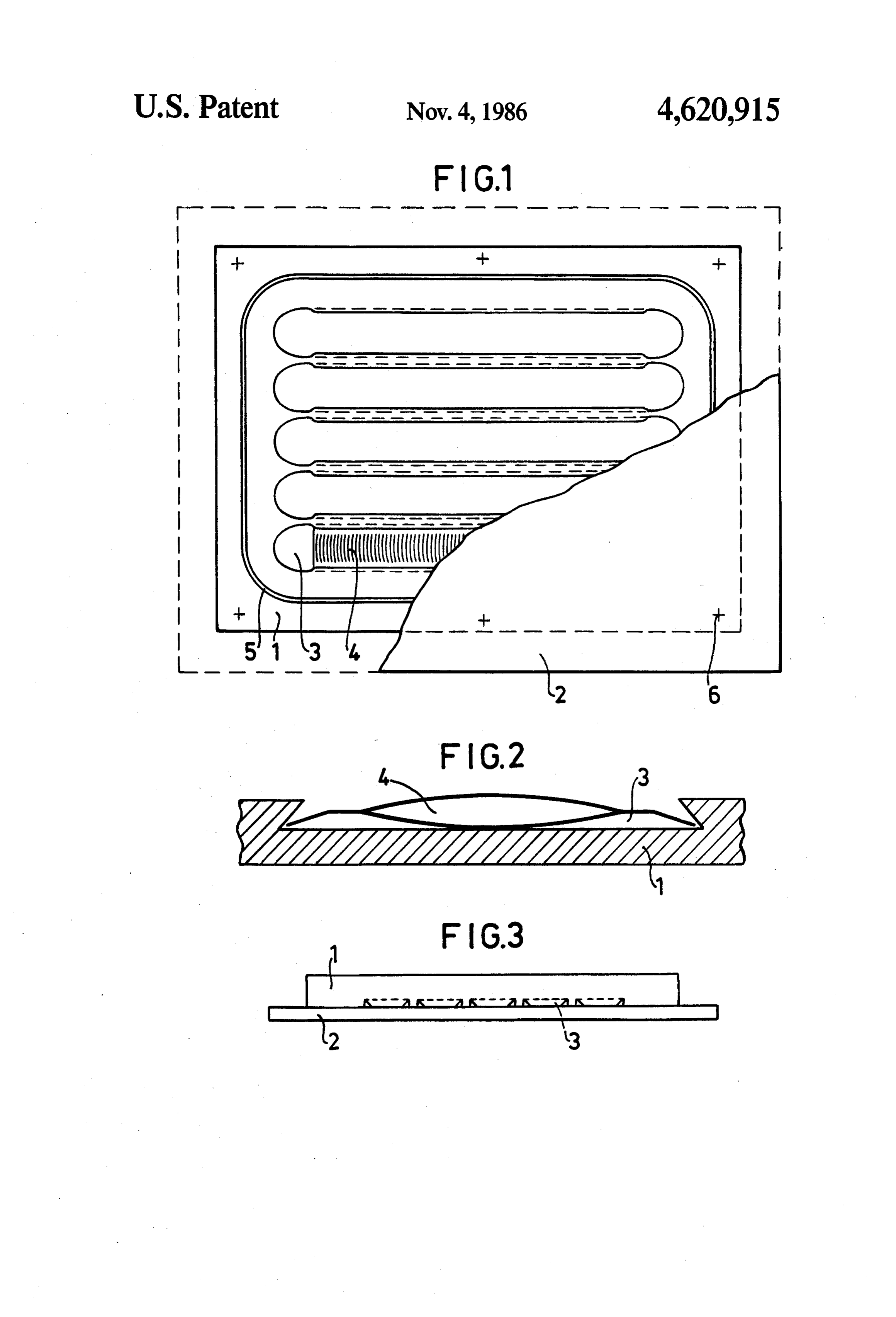
on the anode side but this material will, however, on the BRIEF DESCRIPTION OF THE DRAWINGS cathode side and particularly in contact with suitable cathode materials such as iron easily form titanium FIG. 1 shows a preferred embodiment of a contact hydride which reduces the electrical conductivity and joint according to the invention with a partially re influences the dimensional stability. It can then be suit 45 moved anode.
able to keep the surfaces separated from each other over FIG. 2 shows a cross-section through a recess in one the entire joint area which can be achieved by means of plate with an inserted louver unit.
spacer bodies or by means of inserted sealings. In the FIG. 3 shows in view from one side how the recesses actual contact point between the louvers and the joint are arranged.
surfaces the hydride formation is counteracted by the 50 DESCRIPTION OF DRAWINGS high contact pressure. The purely mechanical joining of the parts can be carried out in different ways and bolt A base plate for a bipolar finger electrode, intended ing or riveting can be used without disadvantages to be provided with electrode fingers perpendicular to owing to the small required contact pressure and hereby the plate on both sides, is formed from a thicker steel material which is not proton conductive can be selected 55 plate 1 with a smaller surface and a thinner titanium for part of the bolt or nail joint or the entire joint if there plate 2 with a larger surface. In the thicker steel plate 1 is a risk of hydride formation. recesses with a surface which increases towards the Independent of the method of joining, the area be bottom have been made but the recesses can alterna tween the contact surfaces must be sealed to prevent tively be arranged in the titanium plate if it is desirable electrolyte penetration and it is particularly important 60 to facilitate replacement of the more corrodible steel to protect the area between the louvers from being plate. Louver units 4 with a plurality of louvers ar affected both by electrolyte and gases to achieve a high ranged in a row are placed in the recesses 3 and the and long-lasting conductivity. Sealings can thus be re individual louvers are at an angle of about 45 to the quired around the louver area and preferably around plates 1 and 2. A sealing 5 which is impermeable to the entire periphery of the electrode parts by using 65 liquid but permeable to hydrogen gas is placed around sealing strips, sealing compounds or soldering with the recesses with the louvers. The plates 1 and 2 are silver solder. When metals which are permeable to mechanically joined by a few bolts or rivets 6 along the atomic hydrogen are present hydrogen gas of a very periphery of the stell plate 1.
Page 6
I claim: louvers being arranged between parts of the base plate 1. A bipolar electrode comprising a two-part base in such a manner that the contact lines of the louvers plate (1,2), one part being the anode side in a cell space between parts of the base plate are essentially parallel to and containing titanium and the other part being the the electrode fingers on the same base plate, and the cathode side in an adjacent cell space and containing 5 space between the parts of the base plate being sealed iron, both parts having electrode fingers fixed essen tially perpendicular to the base plates, wherein electri (5) so as to prevent electrolyte penetration but to allow hydrogen penetration.
cal contact between the base plate is maintained by 2. A biopolar electrode according to claim 1 wherein means of a plurality of elastic and electrically conduc tive louvers (4), said louvers being pressed into contact 10 the louvers are positioned in recesses (3) in the surface with the parts of said base plate by means of a mechani of one of the parts ofsk thesk. base
plate.
cal joint between the parts of the base plate, and said
Provenance
- Collection
- Cited prior art
- Original PDF
- patentimages.storage.googleapis.com →
- Filed
- 1985-01-28
- Pages
- 6
- Method
- pdftotext (the PDF's own text layer) + pdftoppm 300dpi page scans
- Source
- Google Patents bibliographic record
- Granted
- 1986-11-04
- Inventors
- Tommy Ohlin; Kemanord Blekkemi AB
- Transcribed from
- patentimages.storage.googleapis.com →