patent · US4508064
Internal combustion engine of hydrogen gas
2 April 1985
Page 1 — bibliographic record
United States Patent (19) 11 Patent Number: 4,508,064 Watanabe (45. Date of Patent: Apr. 2, 1985 54 INTERNAL COMBUSTION ENGINE OF 3,696,795 10/1972 Smith et al. ................ 123/DIG. 12 HYDROGEN GAS 3,983,882 10/1976 Billings ............. ... 123/DIG. 12
75 Inventor: Kenji Watanabe, Kagoshima, Japan
FOREIGN PATENT DOCUMENTS
73) Assignee: Katsuji BABA, Kagoshima, Japan; a part interest 231000 3/1925 United Kingdom ............. 123/27 G
Primary Examiner-E. Rollins Cross 22 Filed: Sep. 28, 1982 Attorney, Agent, or Firm-Frishauf, Holtz, Goodman & 30 Foreign Application Priority Data Woodward
Nov. 12, 1981 JP Japan ............................... 56-1804.09 (57) ABSTRACT Feb. 3, 1982 JP Japan .................................. 57.1489 A hydrogen gas internal combustion engine provided Feb. 3, 1982 JP Japan .................................. 57-14820 with a hydrogen gas jet nozzle and water spray jet 51) Int. Cl. .............................................. F02B 75/12 nozzle in the combustion chamber to directly jet hydro 52 U.S. C. ........................... 123/1 A; 123/DIG. 12; gen gas and the water spray therein. The sprayed water 123/525 is instantly vaporized to steam by igniting the hydrogen 58) Field of Search ............ 123/1 A, DIG. 12, 25 R, gas thereby utilizing the combustion/explosion energy 123/25 A, 25 D, 25 P, 525 of the hydrogen gas and the steam energy generated (56) References Cited from the vaporization of the steam in a combination to
obtain mechanical dynamic energy.
2,183,674 12/1939 Erren .................................. 123/. A 7 Claims, 6 Drawing Figures
Page 2
Drawing sheet — no readable text.
Page 3
Drawing sheet — no readable text.
Page 4
Drawing sheet — no readable text.
Page 5
Drawing sheet — no readable text.
Page 6
ignition, back fires and knocking even under a high load
INTERNAL COMBUSTION ENGINE OF operation by restricting the thermal energy generated HYDROGEN GAS by the combustion and explosion of hydrogen gas by
BACKGROUND OF THE INVENTION
means of the water spray introduced into the combus 5 tion chamber concurrently with the gas supply.
This invention relates to an internal combustion en Still another object of the invention is to provide a gine which uses hydrogen gas as the fuel for thermal hydrogen gas engine with a higher efficiency in conver energy source and is capable of effectively converting sion of energy into mechanical dynamic energy by va the explosive energy generated by the combustion of 10 porizing the water spray which has been introduced in hydrogen gas into mechanical kinetic energy. the combustion chamber into steam by the heat of com As is well known in the art, since hydrogen gas en busting hydrogen gas and utilizing the effect of com gines are more advantageous than gasoline engines in bined forces of hydrogen gas and the steam. that they have a better mileage and cause less pollution, Yet another object of the present invention is to pro various tests products have been manufactured. Test vide a hydrogen gas engine capable of a smooth opera engines so far manufactured are, however, mostly far tion both under the high and low loads by means of less practical in terms of output, engine configuration separate channels, each of which supplying hdyrogen and weight, economy, etc. when compared with con gas in an amount suitable for either the high or low load ventional type engines of petroleum fuels, and the de operation respectively.
velopment therefor has come to a deadlock.
The fundamental reason why these trial hydrogen 20 SUMMARY OF THE INVENTION engines have not yet reached the stage of practical use The hydrogen gas engine according to the present is that all these attempts were made to directly convert invention is characterized in that hydrogen gas and the the combustion/explosion energy of hydrogen gas into water supply are not mixed in advance but are directly mechanical kinetic energy as is done in conventional introduced into the combustion chamber via separate gasoline engines. 25 nozzles. Hydrogen gas and the water spray are jetted When hydrogen gas is viewed as a fuel for obtaining into the combustion chamber simultaneously or at mechanical dynamic energy, its combustion rate is by slightly staggered timings. As the compressed hydrogen far the greater than that of gasoline, and as a result the gas conversion of its combustion/explosion energy into chamber, the byis ignited the ignition plug in the combustion mechanical dynamic energy becomes very low. The 30 hydrogen gas thermal is energy by the combustion of directly converted into mechanical unconverted thermal energy which remains in the com dynamic energy. At the same time, a portion of the bustion chamber becomes accumulated and causes ab normal temperature rises in the parts which constitute tion chamber to instantly vaporizespray thermal energy causes the water in the combus into steam, whereby the combustion chamber and adjacent parts thereof. explosive thermal energy of hydrogen gas and steam This in turn hampers a smooth supply of hydrogen gas 35 will become combined and converted into mechanical into the combustion chamber and the timely ignition as dynamic energy.
required, whereby proper engine driving becomes im possible. Whereas the combustion rate of hydrogen gas itself is Actual problems encountered in an internal combus high in the hydrogen gas engine of the present inven tion engine using hydrogen gas as the fuel is that al- 40 tion, the rate at which the water spray vaporizes by the though during idling when the fuel supply is limited, the combustion of the gas is relatively slower than the com engine can be kept running by a mixture diluted with bustion rate of gasoline engines, explosion/combustion the air, and a high load operation with an increased fuel of hydrogen gas and vaporization of the water spray supply will cause the premature ignition due to the take place in the same combustion chamber as a series of increase in the hydrogen concentration. Thus, back fires 45 related actions. As a result, the conversion of these and knocking are easily caused and the pressure is rap energies into mechanical dynamic energy may take idly increased. place in a manner similar to that in gasoline engines. In order to overcome this problem, Billings and The hydrogen gas engine according to the present in Daimler-Benz have proposed to supply hydrogen gas vention is thus made capable of effectively utilizing the which is mixed with the water into the combustion 50 thermal energy of hydrogen gas which has otherwise chamber in order to lower the temperature of the con been exhausted when hydrogen gas alone was subjected bustion gas as well as the temperature of overheated to combustion, and increasing the resultant mechanical parts. Previous attempts of this sort have succeeded in dynamic energy.
preventing the back fires and knocking to a certain Further, as the water to be supplied in the combustion extent. But since they must limit the maximum output to 55 chamber together with hydrogen gas is not pre-mixed about 60% of the output obtained by gasoline engines in with the gas, but is directly and separately supplied in order to reduce the heat capacity produced by combus the form of spray, the spray gives rise to steam energy tion and to prevent abnormal combustion, the output in the combustion chamber which is maintained at a capacity cannot be sufficiently increased. high temperature and pressure because of the quickly An object of the present invention is to overcome the 60 burning hydrogen gas. The steam helps to improve the problems heretofore encountered in hydrogen gas en conversion rate of thermal energy of hydrogen gas gines and to provide a feasible engine which is capable combustion into mechanical dynamic energy. The sup of increasing the efficiency in converting the combus ply of the water spray also acts to reduce the thermal tion/explosion energy of hydrogen gas into mechanical energy which remains unconverted in the combustion dynamic energy and which can be put into practical 65 chamber, so that the temperature rise in the parts consti USC. tuting the chamber and adjacent parts can be restricted. Another object of the present invention is to provide The hydrogen gas engine according to the present in a hydrogen gas engine capable of preventing premature vention is thus advantageous in its smooth supply of
Page 7
hydrogen gas into the combustion chamber and the pressurized jetting. The nozzle 6 pressurizes and jets the timely ignition. gas at a predetermined pressure into the cylinder 1. The BRIEF DESCRIPTION OF THE DRAWINGS channel 14 is provided on both sides of the check valve 16 with a by-pass 18 which supplies low pressure gas
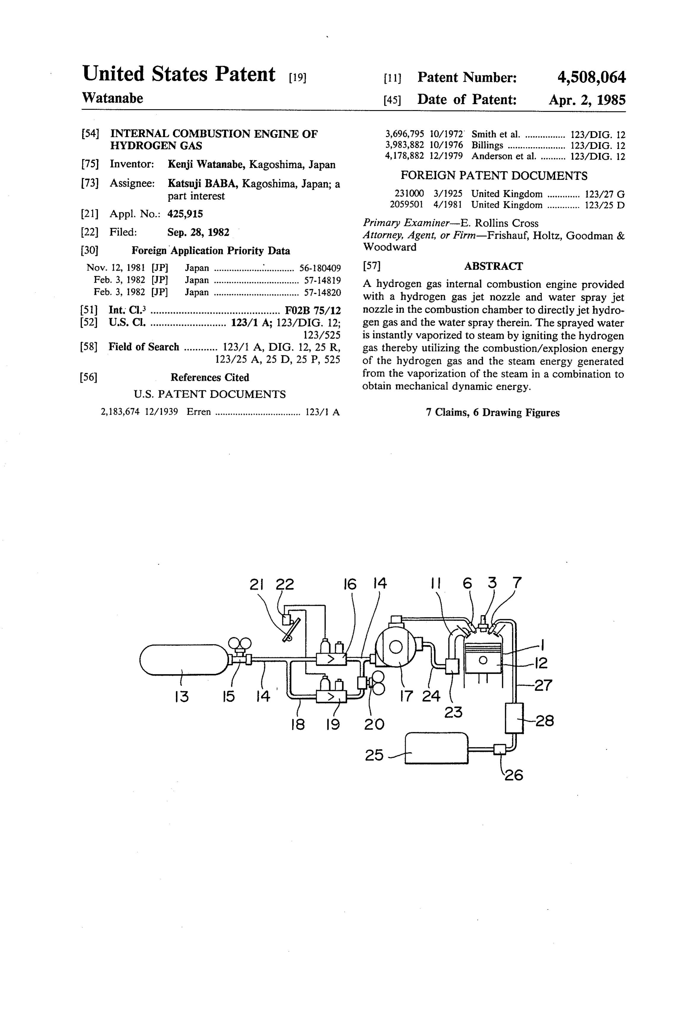
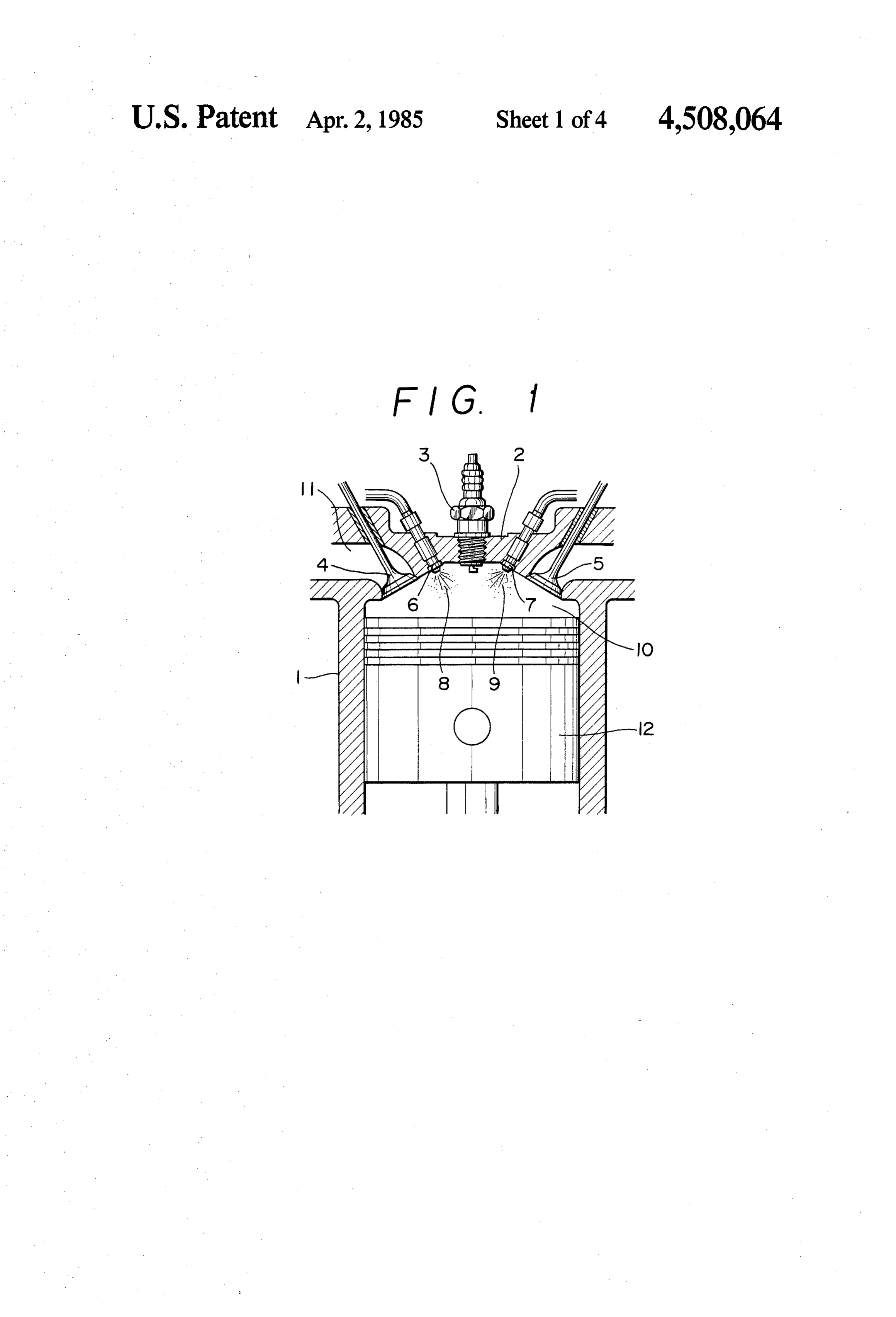
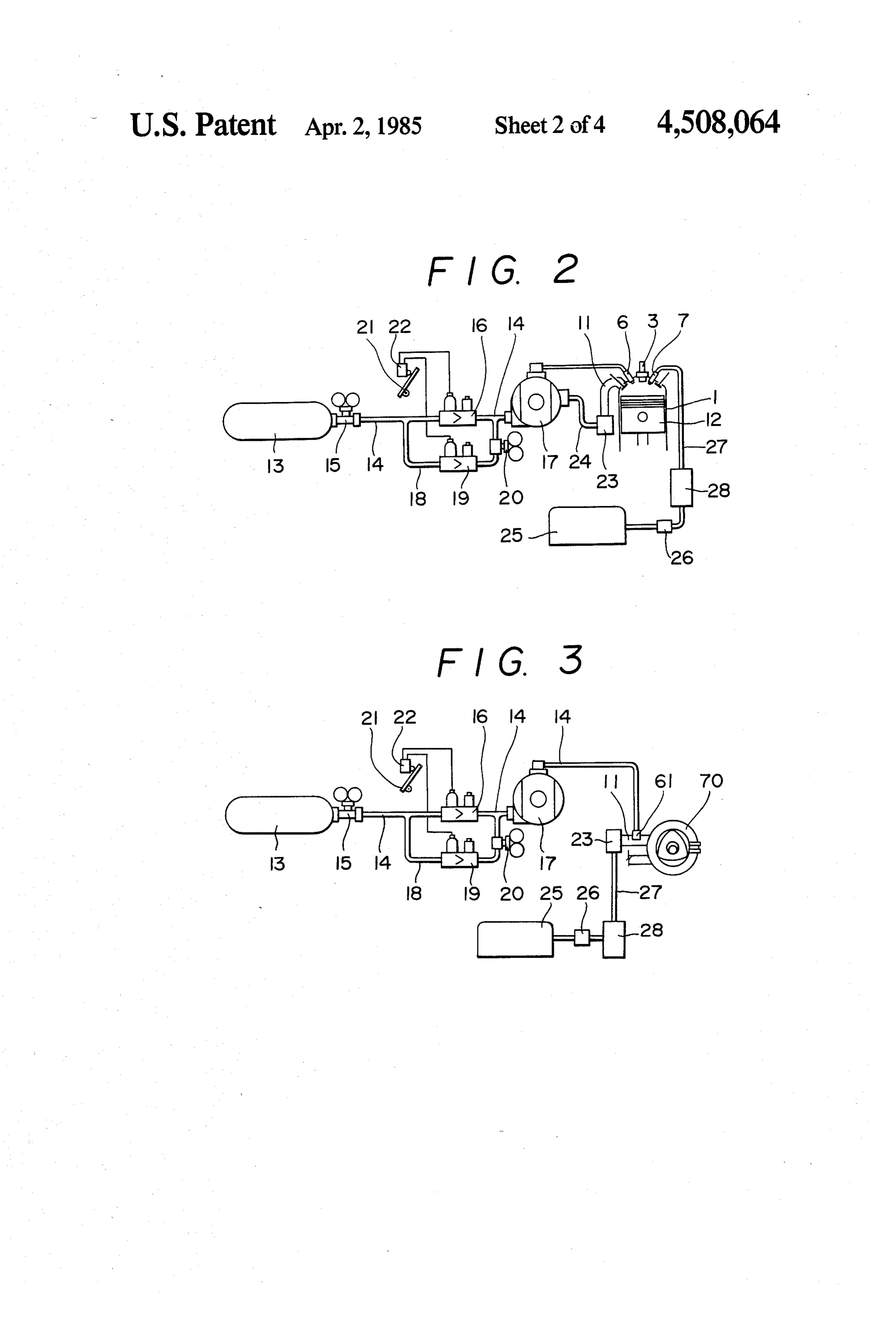
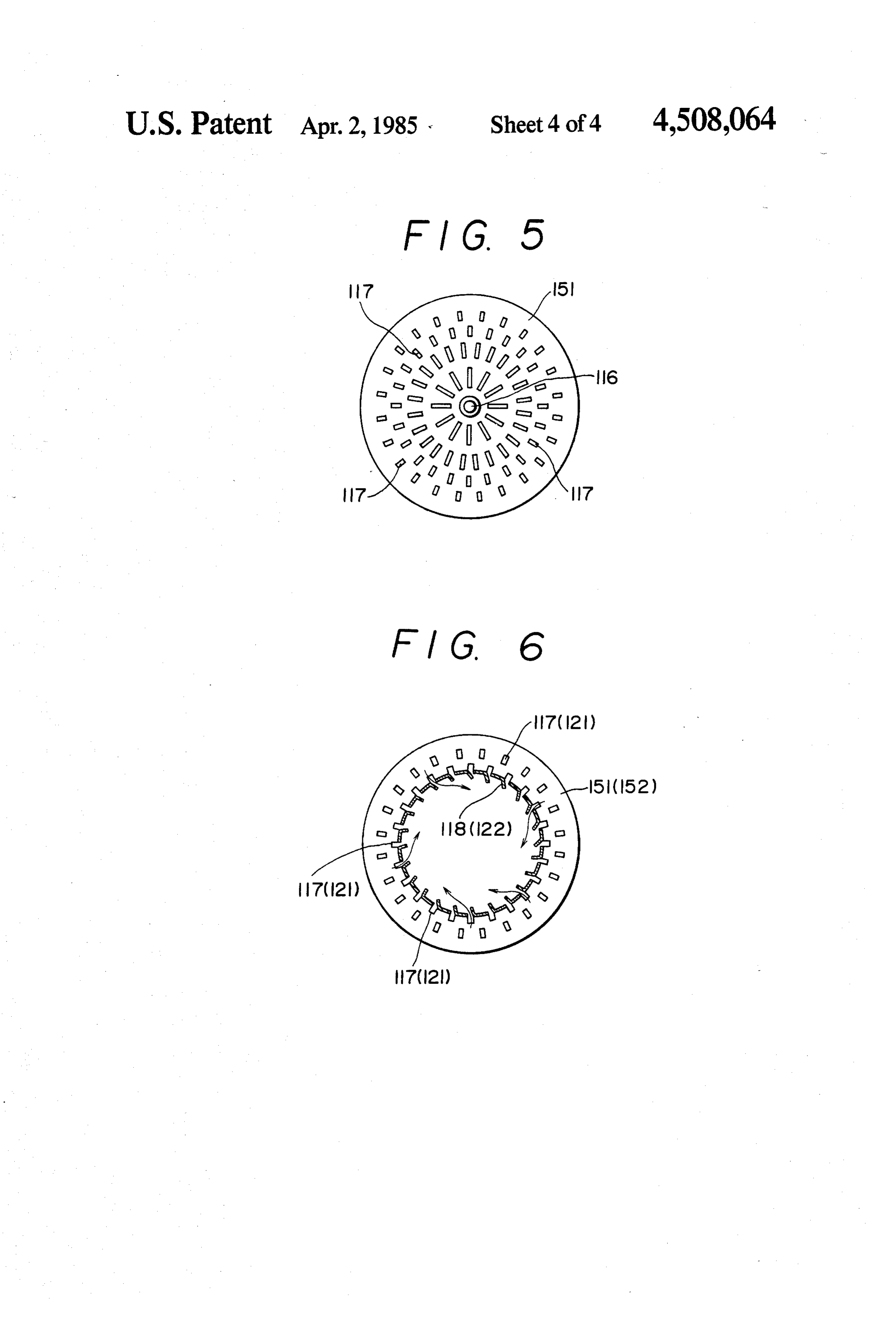
FIG. 1 is a sectional view of the cylinder of a piston during a low load operation and which by-passes the type reciprocating engine to which the hydrogen gas check valve 16. The by-pass 18 is provided with a check engine of the present invention is applied. valve 19 and a pressure control means 20; the pressure FIG. 2 shows the fuel supply system of the hydrogen control means 20 lowers the pressure of hydrogen gas gas engine shown in FIG. 1. sent from the container 13 from about 5 kgf/cm2 to FIG. 3 shows the fuel supply system of a rotary en O about 0.1 kgf/cm2. Hydrogen gas thus lowered in the gine to which the hydrogen gas engine of the present pressure to about 0.1 kgf/cm2 is sent to the regulator 17 invention is applied. via the by-pass 18 during a low load operation such as FIG. 4 is a sectional view of a gas turbine to which idling, when a limit switch 22 provided at an accel pedal the hydrogen gas engine of the present invention is 21 closes as the pedal 21 is released and causes the check applied. 15 valve 19 to open on the by-pass 18 and at the same time, FIG. 5 is a front view of the semi-spherical nozzle it also causes the check valve 16 on the supply channel cover which constitutes the frontal part of the combus 14 to close. Since the predetermined pressure set at the tion cylinder. regulator 17 is greater than the pressure at which the FIG. 6 shows the nozzle cover shown in FIG. 5 gas flows in from the by-pass 18, said gas at a low pres sectioned in part. 20 sure of about 0.1 kgf/cm2 proceeds intact to the nozzle DETAILED DESCRIPTION OF THE 6 for pressurizing and jetting the gas, where the gas is INVENTION pressurized to the predetermined pressure and jetted into the cylinder 1.
FIG. 1 shows a sectional view of the cylinder in a When the accel pedal is stepped on to bring about a reciprocating engine to which the present invention 25 high load operation, said switch 22 opens to cause the applied. As is shown, the cylinder 1 has a cylinder head check valve 19 on the by-pass 18 to close and the check 2 which is provided with an ignition plug 3, an inlet valve 16 on the supply channel 14 to open at the same valve 4 and an exhaust valve 5 together with a nozzle 6 time, whereby the gas from the container 13 is sent to for pressurized jetting of hydrogen gas and a nozzle 7 the regulator 17 to be pressurized to about 0.5 kgf/cm2 for spraying the water that are provided respectively 30 and sent to the nozzle 6 where the gas is further pressur for supplying the hydrogen gas 8 and the water spray 9 ized to the predetermined value before being fed into into the combustion chamber 10. The nozzles 6 for the cylinder 1.
pressurized jetting of the hydrogen gas and the water The amount of gas 8 to be supplied in accordance spraying nozzle 7 jet the hydrogen gas 8 and the water with the changes in the rate of engine rotation can be spray 9 into the combustion chamber 10 from respective 35 controlled by adjusting the flow rate at the regulator 17 sources (not shown) either simultaneously or at slightly by means of a vacuum pipe 24 connecting a carburetor staggered timings. 23 and the regulator 17 in accordance with the degree Hydrogen gas 8 and the water spray 9 are fed during of opening the throttle valve of the carburetor 23. the compression stroke as in the ordinary gasoline en As is described above, by providing the by-pass 18 gines where a piston 12 moves upward and the inlet 40 which can supply hydrogen gas at a pressure lower than valve 4 and the exhaust valve 5 are both closed. Jetting the predetermined pressure and suitable for a low load is respectively cut off just before the piston 12 reaches operation into the supply channel 14, a high load opera the upper dead end, when the compressed hydrogen gas tion which is effected by means of said supply channel is ignited by the ignition plug 3. The thermal energy 14 can be made smoothly, and moreover, a low load generated by combustion of ignited hydrogen gas is 45 operation such as idling can also be maintained smooth directly converted into mechanical dynamic energy. At without trouble by supplying low pressure gas via the the same time, the water spray is converted into steam said by-pass 18. Experiments using a reciprocating en instantly in the combustion chamber which is main gine with 1800 cc capacity and a rotary engine of com tained at a high temperature and pressure due to the mercial automobiles proved that application of the pres quickly burning hydrogen gas, whereby explosive ther 50 ent invention could ensure a smooth operation not only mal energy of hydrogen gas and steam energy are com during a low speed running but also during a higher bined and become a mechanically dynamic energy to speed running of up to 120 kg/h.
press down the piston 12. The exhaust strokes and the The water spray 9 to be sprayed into the cylinder 1 inlet strokes following said explosion strokes are the together with hydrogen gas 8 is supplied from a tank 25 same as those in the ordinary gasoline engine. 55 (at ambient temperature; i.e., "room' or "normal" tem FIG. 2 shows the fuel supply system of an automobile perature) via a pipe 27 provided with a feed pump 26 by engine of reciprocating type to which the present hy regulating the supply amount in correspondence with drogen gas engine is applied. Hydrogen gas 8 is pressur the changing rate of engine rotation by means of a spray ized and directly jetted into the cylinder 1 from a con pump 28 which is controlled in accordance with the tainer 13 via a gas supply channel 14 without passing a 60 engine rotation.
carburetor 23. The channel 14 supplies hydrogen gas at FIG. 3 shows the fuel supply system of a rotary en a pressure of about 5 kgf/cm2 by means of a pressure gine to which the present invention is applied. In this control means 15 provided at the mouth of the con case, the supply system for hydrogen gas 8 is identical tainer 13. There are provided at an intermediate point in with said reciprocating engine mentioned above, but the the channel a check valve 16 and a regulator 17 which 65 supply system for the water spray is somewhat differ reduce the pressure and regulate the flow rate. Hydro ent. In the rotary engine, the water is supplied from the gen gas passes through the regulator 17 and flows at a tank 25 to the carburetor 23 via a feed pump 26, and said low pressure of about 0.5 kgf/cm2 into the nozzle 6 for carburetor 23 atomizes and sprays the water into a rotor
Page 8
housing 70 via the inlet port 11 together with the air. On thereby expanding the area of combustion and improv the other hand, hydrogen gas 8 is jetted into the inlet ing the inflammability.
port 11 via a nozzle 61 provided on the inlet port 11. It The combustion gas produced by the explosion in the should be noted that the hydrogen gas 8 and the water front combustion zone 126 enters in vortex into the rear spray 9 are introduced into the inlet port 11 via separate combustion zone 127 through the apertures 121 for channels. In other words, hydrogen gas 8 is supplied in guiding the gas on the rear nozzle cover 152 which the inlet port provided at immediate anterior of the separates the primary combustion gas and vaporizes the rotor housing 70 via a separate channel 14, just before water 124 sprayed into said zone 127. The steam thus the mixture of the water spray and the air is supplied produced imparts expansive energy to the combustion into the rotor housing 70. This is the fundamental differ 10 gas coming into the rear combustion zone 127 through ence of the present invention from the conventional the apertures 121 on the nozzle cover 152 and from the type in which hydrogen gas, the water and the air are side of the cover. As for the generation of the steam mixed in advance before being supplied into the cylin energy in the rear combustion zone 127, the water spray der. coming from the nozzle 120 can be effectively diffused FIG. 4 shows an embodiment of the present invention 15 and the area where the steam is formed may be ex using a gas turbine. In the drawing, the reference num panded as the combustion gas enters in vortex from the ber 111 represents an air inlet port, 112 a compressor, apertures 121. The high temperature gas which is 113 an inlet port for the pressurized air, 114 a turbine caused by a combination of the combustion energy casing, and 115 a combustion cylinder. The tip of the produced in the zone 127 and the steam power due to combustion cylinder 115 constitutes a semi-spherical 20 vaporization of the water is transferred to the rear of the nozzle cover 151. At the center inside a front nozzle combustion cylinder 115 and is subsequently supplied to cover 151 is provided a nozzle 116 for jetting hydrogen a power turbine 128 while being cooled by the air sup gas. As shown in FIGS. 5 and 6, a plurality of apertures plied from the air holes 125 at the rear of the said cylin 117 for deflecting and introducing the air are provided der.
around the nozzle 116 for discharging hydrogen gas. 25 In this turbine which embodies the present invention, These apertures are provided radially from the nozzle the area where the high temperature gas is formed is 116 and have guide fins 118 therein so that the com divided into two parts: the front combustion zone 126 pressed air around the nozzle cover 151 can be de where the combustion gas is produced by hydrogen gas flected toward its inside when the said air is introduced 123; the rear combustion zone 127 where the steam into the combustion cylinder 115. 30 power is produced by the water spray 124 to be con An ignition plug 119 is provided behind the nozzle tacted with the said combustion gas. This enables sup 116 for hydrogen gas, and a rear nozzle cover 152 ply of the water spray sufficient to produce the steam which is semi-spherical in shape like the front nozzle power in the combustion cylinder 115 which is to be cover 151 is provided behind the ignition plug 119. The added to the high temperature gas produced by the rear nozzle cover 152 is also provided radially about a 35 combustion of hydrogen gas. If the water spray and nozzle 120 for the water spray with a plurality of aper hydrogen gas are mixed in advance and supplied at the tures 121 having guide fins at the inside for deflecting same time, the jet pressure of hydrogen gas would ob and introducing the combustion gas. struct the water spray in such a way that the particle Hydrogen gas 123 and the water spray 124 are jetted size of the water spray cannot be reduced sufficiently from the nozzles 116 and 120 respectively while the air 40 enough, and thus the steam power which is to impart compressed by the compressor 112 is being fed from the sufficient expansive force to the combustion gas cannot turbine casing 114 toward the combustion cylinder 115 be generated.
via the apertures 117 for deflecting and introducing the As has been described above, the present invention air which are provided at the front nozzle cover 151 and can effectively convert the combustion/explosion en via the air holes 125 provided at the side of the combus 45 ergy of hydrogen gas into mechanical dynamic energy tion cylinder. When the ignition plug 119 placed behind by combining the steam energy, and therefore assures a the hydrogen gas nozzle 116 is actuated at this state, hydrogen gas engine to be put into practical use as a hydrogen gas 123 burns continuously at a higher pres new power source which has been considered difficult sure in the front combustion zone 126 located behind heretofore.
the hydrogen gas nozzle 116. At the same time, the 50 What we claim is:
water spray124 is introduced in the zone located behind 1. In a hydrogen gas fueled internal combustion en the rear nozzle cover 152 which is located behind the gine, the improvement comprising: combustion zone 126 and contacted with combusting a hydrogen gas jet nozzle provided in a combustion hydrogen gas 123 to be vaporized in the rear combus chamber of the engine to directly jet hydrogen gas tion zone 127 located behind the rear nozzle cover 152. 55 as fuel into the combustion chamber; Thus, the combustion energy of hydrogen gas and the a source of water at ambient or room temperature; steam power of the water spray are combined in the and combustion cylinder to continuously produce expansion a water spray jet nozzle coupled to said water source, energy. said water spray jet nozzle being provided in said In other words, since the compressed air to be intro 60 combustion chamber, separately and independently duced in the combustion cylinder 115 is directed rotat of said hydrogen gas jet nozzle, to directly jet a ingly and spirally toward the inner periphery of the spray of said ambient or room temperature water front combustion zone 126 in the cylinder from the into said combustion chamber substantially simul apertures 117 (for deflecting and introducing the air) taneously with the jetting in of the hydrogen gas; provided at the front nozzle cover 151, a negative pres 65 the air in said combustion chamber being compressed sure zone is formed behind the nozzle 116 in said com so that the water sprayed into said combustion bustion zone 126 as the center of the vortex. This pro chamber is instantly vaporized to steam by igniting notes jetting of hydrogen gas 123 and its diffusion, of the hydrogen gas jetted into said combustion
Page 9
chamber, thereby utilizing the combustion/explo 5. The hydrogen gas fueled internal combustion en sion energy of the hydrogen gas and the steam gine of claim 1, wherein said internal combustion engine energy generated from the vaporization of the is a gas turbine engine having a cylinder defining a steam in combination to obtain mechanical dy combustion chamber, the tip of said combustion cham namic energy. 5 ber comprising a semi-spherical front nozzle cover hav 2. The hydrogen gas fueled internal combustion en ing at its center said hydrogen gas jet nozzle, a rear gine of claim 1, wherein said internal combustion engine nozzle cover being arranged inside said combustion is a piston-type reciprocating internal combustion en chamber and having at its center said water spray jet gine having at least one cylinder and a cylinder head nozzle, whereby continuous flowing gas in said com closing said cylinder, and wherein said hydrogen gas jet 10 bustion chamber is combined with steam energy gener nozzle and said water spray jet nozzle are provided in ated by vaporization of the water spray to produce said cylinder head. mechanical dynamic energy. 3. The hydrogen gas fueled internal combustion en 6. The hydrogen gas fueled internal combustion en gine of claim 1, wherein said internal combustion engine gine of claim 5, wherein said front and rear nozzle cov is a rotary engine having a combustion chamber and a 15 ers respectively are provided with apertures arranged rotor rotatably mounted in said combustion chamber, radially around the respective nozzles for guiding air, said combustion chamber having an inlet port, said said nozzle covers each further having guide fins for hydrogen gas jet nozzle being provided in said inlet port deflecting and dispersing compressed air inside said for introducing hydrogen gas just before the mixture of apertures at a given deflection angle. said water spray and air is introduced into said combus 7. The hydrogen gas fueled internal combustion en tion chamber via said inlet port. gine of claim 7, further comprising a semi-spherical 4. The hydrogen gas fueled internal combustion en front nozzle cover and a rear nozzle cover arranged in gine of any one of claims 1, 2, or 3, further comprising said combustion chamber, said front nozzle cover hav a hydrogen gas supply channel coupled between a hy ing said hydrogen gas jet nozzle mounted thereto and drogen gas container and said combustion chamber, 25 said rear nozzle cover having said water spray jet noz said hydrogen gas supply channel including a low pres zle mounted thereto, said nozzle covers respectively sure hydrogen gas supply by-pass means for closing said being provided with apertures arranged radially around hydrogen gas supply channel under low load operating the respective nozzles for guiding air, and said nozzle conditions of said engine and for supplying said hydro covers each further having guide fins for deflecting and gen gas to said combustion chamber at a pressure lower 30 dispersing compressed air inside said apertures at a than the supply pressure in said hydrogen gas supply given deflection angle.
channel. ck ck k ck ck
Page 10
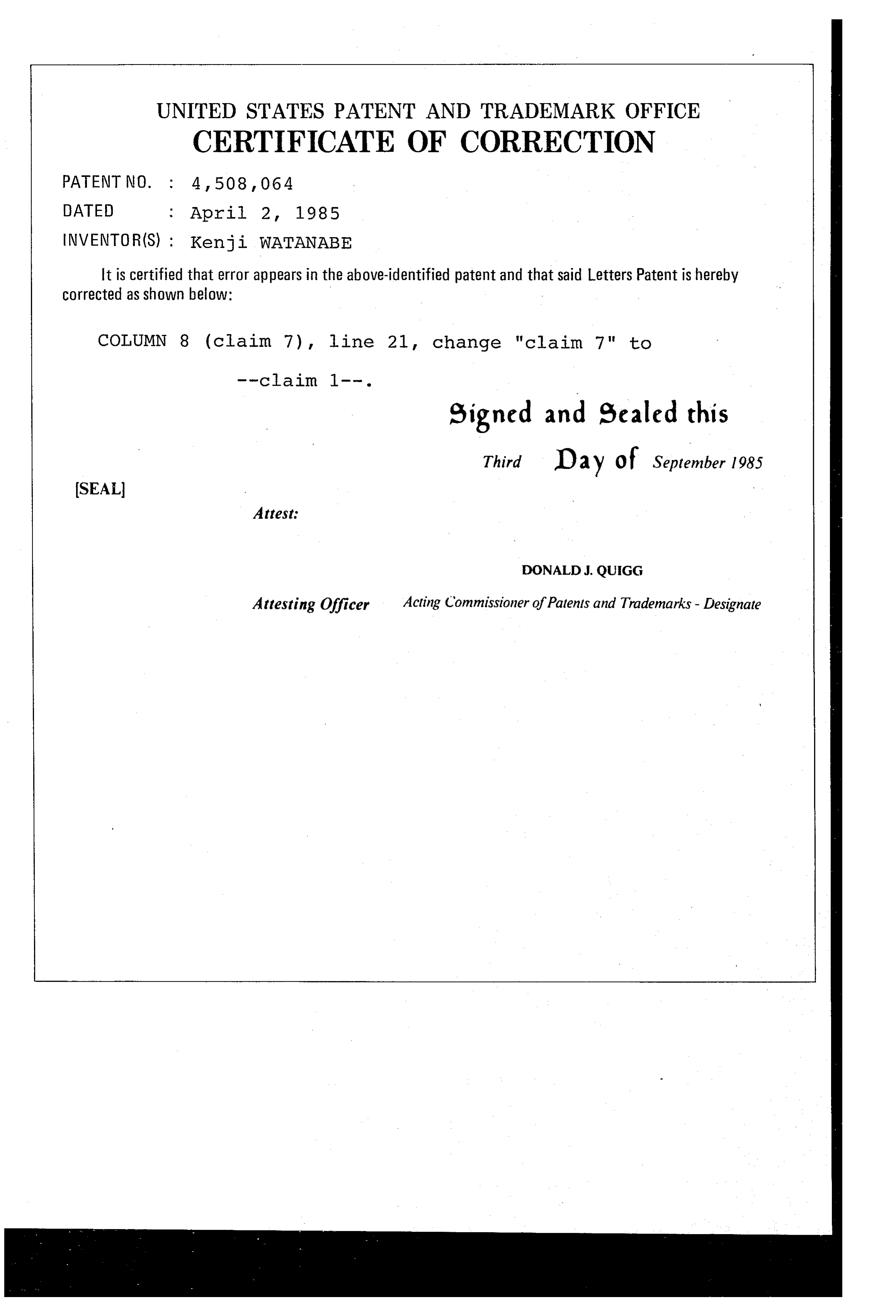
UNITED STATES PATENT AND TRADEMARK OFFICE
CERTIFICATE OF CORRECTION
INVENTOR(S) : Kenji WATANABE
It is certified that error appears in the above-identified patent and that said Letters Patent is hereby Corrected as shown below:
COLUMN 8 (claim 7), line 21, change "claim 7" to
eigned and sealed this
Third D 2 y of September 1985
SEAL
Attest:
DONALD.J. QUIGG
Attesting Officer Acting Commissioner of Patents and Trademarks - Designate
Provenance
- Collection
- Cited prior art
- Original PDF
- patentimages.storage.googleapis.com →
- Filed
- 1982-09-28
- Pages
- 10
- Method
- pdftotext (the PDF's own text layer) + pdftoppm 300dpi page scans
- Source
- Google Patents bibliographic record
- Granted
- 1985-04-02
- Inventors
- Kenji Watanabe; KATSUJI BABA
- Transcribed from
- patentimages.storage.googleapis.com →