patent · US5677972A
High efficiency direct coupling of radiant electromagnetic energy into dielectric wave guide structure
14 October 1997
Page 1 — bibliographic record
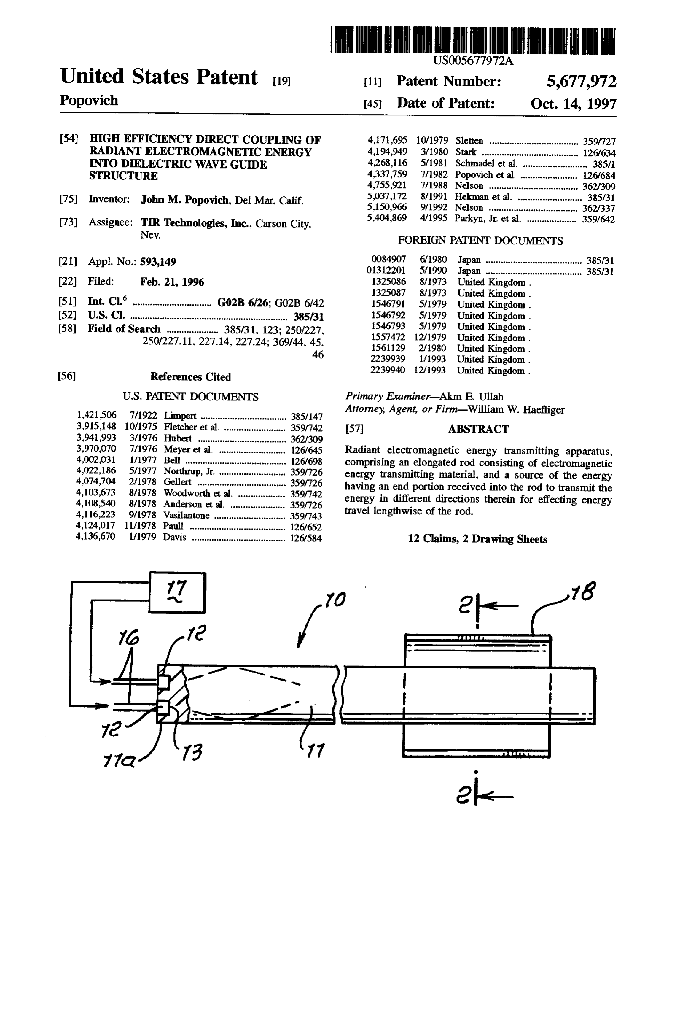
United States Patent 19 11) Patent Number: 5,677.972 Popovich 45) Date of Patent: Oct. 14, 1997 54) HIGH EFFICIENCY DIRECT COUPLING OF 4,171,695 10/1979 Sletten .................................... 359/727 RADIANTELECTROMAGNETC ENERGY 4,194,949 3/1980 Stark ................ ... 126/634 INTO DELECTRICWAVE GUIDE 4,268,116 5/1981 Schmadel et al. .......................... 38.5/1 STRUCTURE 4,337,759 7/1982 Popovich et al. ... ... 126/684 4,755,921 7/1988 Nelson ................. ... 362/309 75) Inventor: John M. Popovich, Del Mar, Calif. 5,037,172
73) Assignee: TIR Technologies, Inc., Carson City, 5,404,869 4/1995 9 Parkyn, Jr. et
Nev. FOREIGN PATENT DOCUMENTS 0084907 6/1980 Japan ....................................... 385/31 (21) Appl. No.: 593,149 01312201 5/1990 Japan ....................................... 385/31 22 Filed: Feb. 21, 1996 1325086 8/1973 United Kingdom.
(51) Int. Cl. .................... G02B 6/26: G02B 6/42 1546791 5/1979 United Kingdom. 52 U.S. C. ........... 1546792 5/1979 United Kingdom. 58) Field of Search ..................... 385/31. 123; 250/227, E. E. E.E.N.
nited Kingdom.
250/227.11, 227.14, 227.24; 369/44, 45, 1561129 2/1980 United Kingdom.
References Cited 2239940 12/1993 United Kingdom.
1,421,506 7/1922 Limpert ................................. 38.5/147 Attorney; Agent, or Firm-William W. Haefliger 3,915,148 10/1975 Fletcher et al. . ... 359,742 57 ABSTRACT 3,941,993 3/1976 Hubert ........... ... 362/309 3,970,070 7/1976 Meyer et al. ........................... 1267645 Radiant electromagnetic energy transmitting apparatus, 4.002031 1/1977 Bell ......................................... 126/698 comprising an elongated rod consisting of electromagnetic 4,022, 186 5/1977 Northrup, Jr. ........................... 359/726 energy transmitting material, and a source of the energy 4,074,704 2f1978 Gellert ................ ... 359/726 having an end portion received into the rod to transmit the 4,103,673 8/1978 Woodworth et al. ... ... 359/742 4,108,540 8/1978 Anderson et al. ...................... 359/726 energy in different directions therein for effecting energy 4,116.223 9/1978 Vasilantone ..... ... 359/743 travel lengthwise of the rod.
4,124,017 11/1978 Paul ...... ... 126/652 4,136,670 1/1979 Davis ...................................... 126,584 12 Claims, 2 Drawing Sheets
Page 2
Drawing sheet — no readable text.
Page 3
Drawing sheet — no readable text.
Page 4
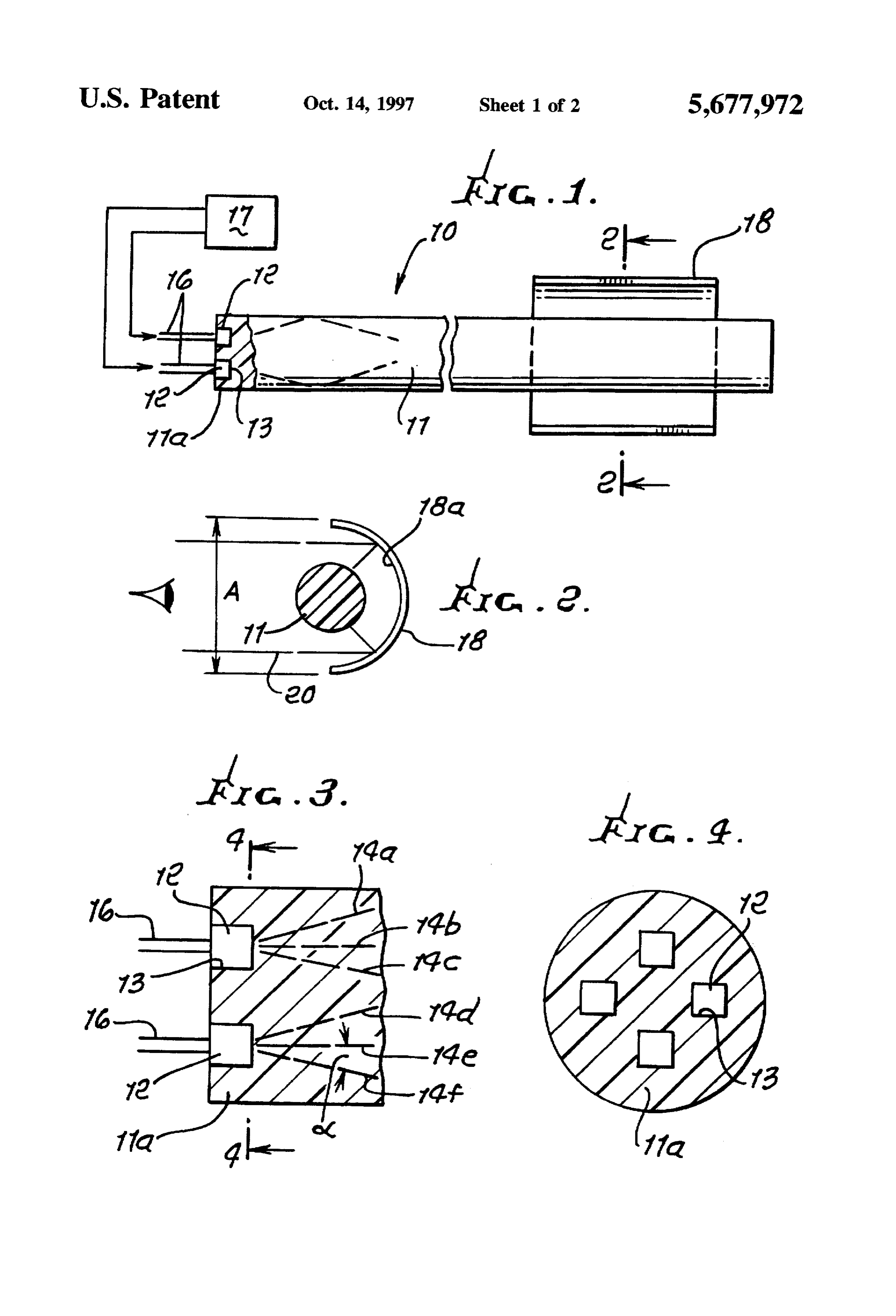
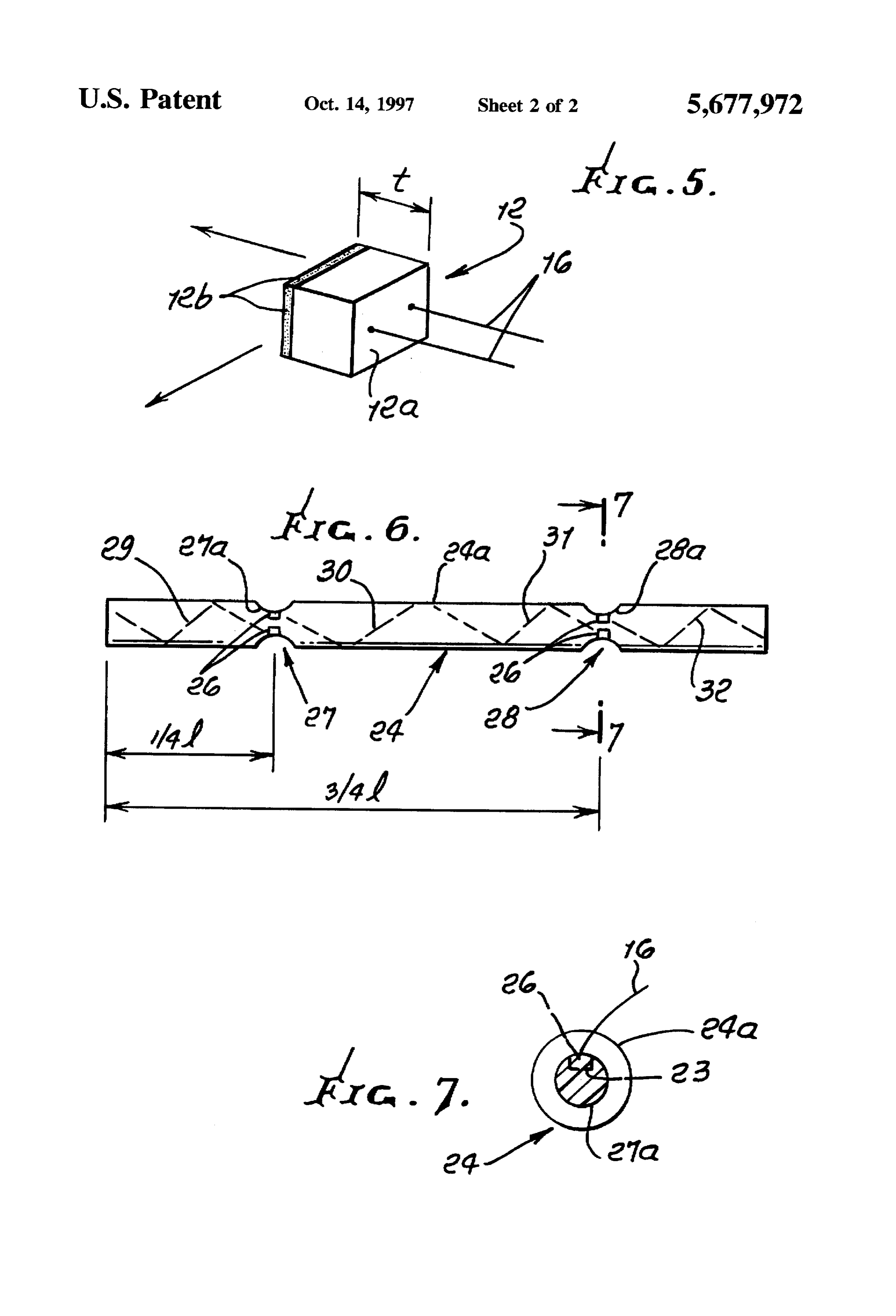
HGH EFFICIENCY DIRECT COUPLNG OF FIG. 5 is an enlarged perspective view showing an LED RADANT EECTROMAGNETC ENERGY of the type used in FIGS. 1-4;
INTO DELECTRC WAVE GUIDE FIG. 6 is a view like FIG. 1, but showing light sources STRUCTURE embedded in reduced cross sectional zones along a light BACKGROUND OF THE INVENTION transmitting rod; and
This invention relates generally to coupling of radiant 6. FIG. 7 is an enlarged section taken on lines 7-7 of FIG. electromagnetic energy into solid dielectric wave guide structure, and more particularly to efficient coupling of light DETALED DESCRIPTION from light sources into light transmitting media for travel 10 Referring first to FIGS. 1-4, radiant energy transmitting therein.
apparatus is indicated generally at 10, such energy for
There is need for simple, efficient coupling of electro example consisting of light, as in the visible wave length magnetic energy, such as light from LEDs, into solid wave zone of the spectrum. The apparatus includes an elongated guide structures such as rods, slabs and etc. Apparatus of this type can be formed into many shapes for a large number of 15 wave guide such as a rod 11 consisting of electromagnetic uses, one example being lighting conformed to or fitting energy, transmitting energy material, and a source or sources of such each having an end portion recessed into the rod to external or internal locations on vehicles, and in or on transmit energy in a preferred direction, for effecting energy buildings, or displays of many types. travel lengthwise of (i.e. along) the rod. See for example the SUMMARY OF THE INVENTION LEDs 12 received in recesses 13 in the end portion 11a of It is a major object of the invention to provide simple, the end rod, so that the LEDs are effectively embedded in the rod portion. Light from the LEDs is shown being transmit efficient and rugged apparatus meeting the above need. ted in different directions 14a-14f over a range of angles, Basically, the radiant electrical energy transmitting appa these showings being illustrative only. A large portion of ratus of the invention comprises: such light is typically (i.e. within cone of angle) transmitted a) an elongated element consisting of electromagnetic 25 as rays extending at angles such as to enable successive total energy transmitting material, internal reflections off the boundary or periphery of the rod, b) and a source of such energy having an end portion along its length, for travel lengthwise along and internally of received into the element to transmit energy in different the rod. As shown, the LEDs may be completely embedded, directions therein for effecting energy travel length 30 along their lengths in the rodend portion, and may have tight WSe. wall-to-wall fits in the recesses 13. LED terminals appear at As will appear, the element such as a rod or wave guide 16, and a low voltage source 17 is schematically shown or may consist of light transmissive material which is bendable connected with such terminals, in FIG. 1. The rod typically to desired shape, and the light source end portion, such as an consists of synthetic polymeric material, and may be flexible LED, is advantageously and protectively received in a recess 35 so as to be bendable. The rod may be considered as a "wave in the wave guide, or embedded in the latter. In this regard guide", i.e. to guide the light waves for transmission length the rod or wave guide may consist of synthetic polymeric wise of the rod. Usable synthetic polymer include polymers material. of silicone, urethane, epoxy, polyamid, acrylic, polyesters Another object is to provide the light source receiving and others. Glasses are usable. These are transparent. recess at an end portion of the rod or wave guide, or FIGS. 1 and 2 also show a reflector 18 located at one side sidewardly at a location along its length. Multiple such of the rod. Light emanating from the rod is reflected, as for recesses may be provided, for reception of multiple light example as shown by rays 20 reflected from the interior sources, such as LEDs. curved surface 18a of the reflector. The reflector may take Yet another object is to provide rod opposite side wall the form of discreet light scattering dots, with varying extents which are relatively convergent at the recess loca 45 spacing to provide uniformity of collimated light reflection tion. Such a rod or wave guide may, for example, have as viewed from the aperture A.
reduced cross-sectional area at or proximate such locations. FIG. 5 shows one form of LED 12 having a cube shape, Such locations may be provided at or proximate to 4 and/or with terminals 16 projecting from the end wall 12a. Light % "l", along rod length "l". for efficient light coupling into generated by the LED emanates from different walls such as the rod. 50 all five remaining walls 12b. Recesses 13 in the rod may A further object is to efficiently couple LEDs to a syn have cube shape for embedding such LEDs, with tight fits, thetic resinous, light transmitting rod or rods. A typical cube dimension t is 0.01 inch. These and other objects and advantages of the invention, In the form of the invention shown in FIGS. 6 and 7, the as well as the details of an illustrative embodiment, will be more fully understood from the following specification and 55 rod atsource light
receiving recess is formed sidewardly into the location along the rod length. See recesses 23 which drawings, in which: are spaced inwardly of the cylinderformed outer surface 24a DRAWING DESCRIPTION of rod 24. Light sources such as LEDs embedded in such FIG. 1 is an elevation showing one preferred form of recesses appear at 26. Preferably, the rod is "necked down" at recess general locations 27 and 28 along the rod length, apparatus incorporating the invention; and has narrowed or venturi shape at such locations. The FIG. 2 is an elevation taken in section on lines 2-2 of recesses are formed in rod side wall extents 27a and 28a FIG. 1; which are axially tapered or relatively convergent, as shown, FIG. 3 is an enlarged section taken in elevation through whereby the LEDs in such recesses are well positioned to one end of a light transmitting rod, showing LED embed transmit light lengthwise of the rod, as indicated by broken ding; 65 line rays 29, 30, 31 and 32 extending from the LEDs and FIG. 4 is an elevation taken in section on lines 4-4 of traveling along and internally of the "wave guide" rod. FIG. 3; Maximum light transmission throughout the rod is effected
Page 5
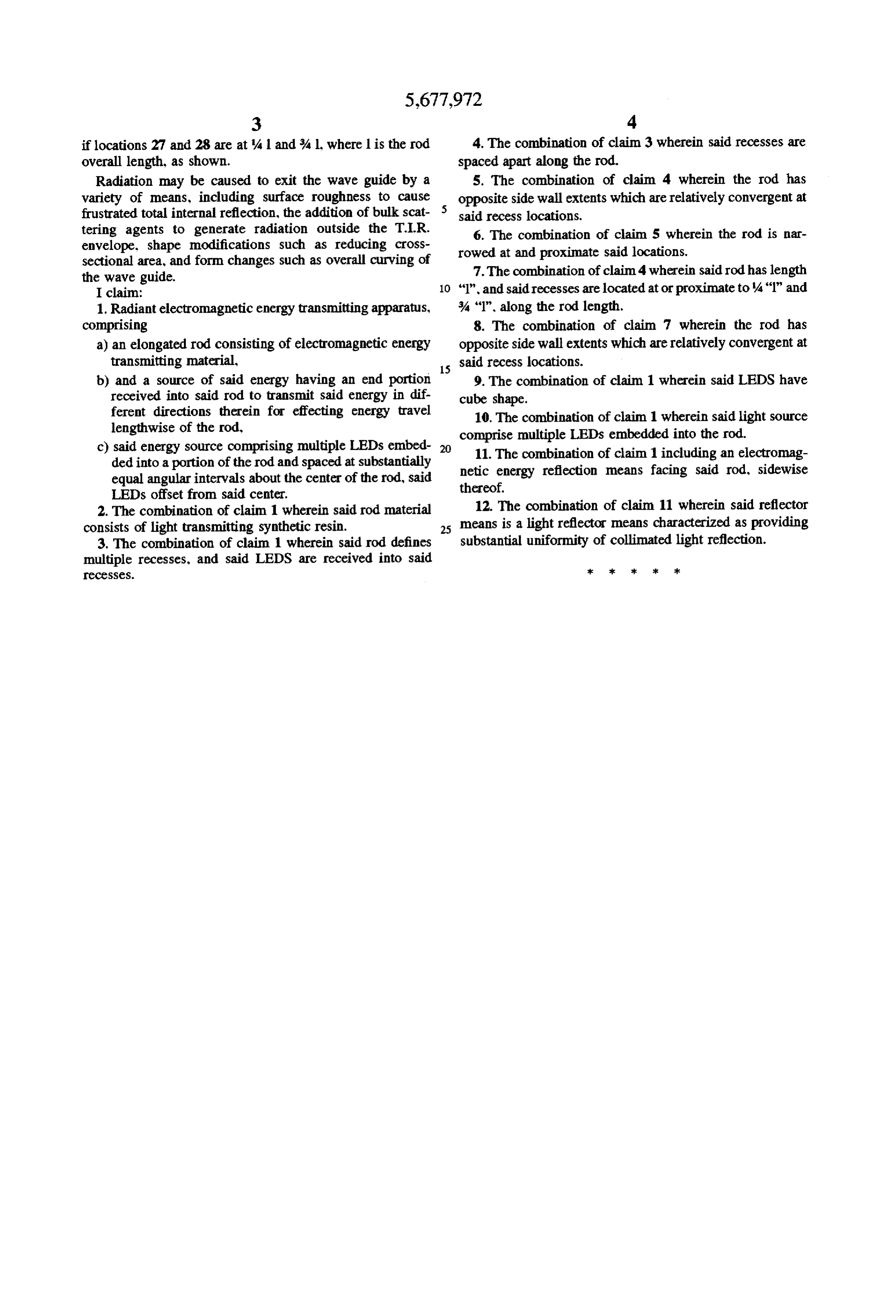
if locations 27 and 28 are at 41 and % l, where 1 is the rod 4. The combination of claim 3 wherein said recesses are overall length, as shown. spaced apart along the rod.
Radiation may be caused to exit the wave guide by a 5. The combination of claim 4 wherein the rod has variety of means, including surface roughness to cause opposite side wall extents which are relatively convergent at frustrated total internal reflection, the addition of bulk scat said recess locations.
tering agents to generate radiation outside the T.I.R. 6. The combination of claim 5 wherein the rod is nar envelope, shape modifications such as reducing cross rowed at and proximate said locations.
sectional area, and form changes such as overall curving of the wave guide. 7. The combination of claim 4 wherein said rod has length I claim: "l", and said recesses are located at or proximate to 4"1" and 1. Radiant electromagnetic energy transmitting apparatus, % "1", along the rod length.
comprising 8. The combination of claim 7 wherein the rod has a) an elongated rod consisting of electromagnetic energy opposite side wall extents which are relatively convergent at
said recess locations.
b) and a source of said energy having an end portion 9. The combination of claim 1 wherein said LEDS have received into said rod to transmit said energy in dif cube shape.
ferent directions therein for effecting energy travel 10. The combination of claim 1 wherein said light source lengthwise of the rod, comprise multiple LEDs embedded into the rod. c) said energy source comprising multiple LEDs embed 11. The combination of claim 1 including an electromag ded into a portion of the rod and spaced at substantially netic equal angular intervals about the center of the rod, said thereof.energy reflection means facing said rod, sidewise LEDs offset from said center.
2. The combination of claim 1 wherein said rod material 12. The combination of claim 11 wherein said reflector consists of light transmitting synthetic resin. 25 means is a light reflector means characterized as providing 3. The combination of claim 1 wherein said rod defines substantial uniformity of collimated light reflection. multiple recesses, and said LEDS are received into said sk sk sk ck sk CCCSSeS.
Provenance
- Collection
- Patents citing this work
- Original assignee
- TIR Technologies Inc
- Current assignee
- TIT TECHNOLOGIES Inc, Teledyne Technologies Inc
- Pages
- 5
- Method
- pdftotext (the PDF's own text layer) + pdftoppm 300dpi page scans
- Patent office record
- patents.google.com →
- Source
- Google Patents citing-documents table
- Inventors
- John M. Popovich; TIR Technologies Inc
- Published
- 1997-10-14
- Transcribed from
- patentimages.storage.googleapis.com →