patent · US5037172
Fiber optic device with a reflective notch coupler
6 August 1991
Page 1 — bibliographic record
United States Patent (19.
Hekman et al.
11) Patent Number:
(45) Date of Patent:
54 FIBER OPTIC DEVICE WITH A 4,558,920 12/1985 Newton et al. .................. 350/96.15 REFLECTIVE NOTCH COUPLER 4,676,584 6/1987 Perlin ............. ... 350/96.15
75 Inventors: Edwin D. Hekman, Chula Vista; 4,863,229 9/1989 Yasui...... ... 350/96. 10 Thomas J. Lund, San Diego; John L. 4,872,739 10/1989 Kahn et al. ....................... 350/96.6 Maida, La Jolla; Deepak Varshneya, OTHER PUBLICATIONS
Del Mar, all of Calif.
73 Assignee: Teledyne Industry, Inc., Los Angeles, Interim Report Number TRE/SD104865-1 for Tele Calif. dyne Ryan Electronics dated Jul. 25, 1986, Army Con
(21) Appl. No.: 626,235 Eigth-Terminal, Bidirectional, Fiber Optic Trunk Data (22) Filed: Dec. 11, 1990 Bus, Nov. 15, 1975, by Daniel E. Altman, Report Num ber NELC Technical Report 1969 (TR 1969).
Related U.S. Application Data Interim Report for an Advanced Optical Position Transducer, Report No. TRE/SD104865-1, Jul. 25, (63) Continuation of Ser. No. 326,965, Mar. 22, 1989, aban 1986.
doned.
Primary Examiner-John D. Lee (51) Int. Cl. ................................................ GO2B 6/26 Attorney, Agent, or Firm-Baker, Maxham, Jester & (52) U.S. Cl. ....................................... 385/31; 385/123 Meador
350/96.20, 96.29, 96.30, 250/227, 227.11, (57) ABSTRACT 227.14, 227.24; 369/44, 45, 46 A structure and a method of manufacturing a reflective (56) References Cited notch coupler for an optical fiber are disclosed. The
surfaces extending from the cladding of the optical fiber 4,173,390 liv1979 Kach ................................ 350/96.16 and meeting in the fiber's core to form an indentation in 4,307,932 12/1981 Winzer ............................. 350/96.15 the fiber. One surface is reflectively coated and couples 4.333,009 6/1982 Stevens ............................... 250/237 4,346,961 8/1982 Porter ...... 350/96.16 light into and out of the core of the optical fiber. 4,356,395 10/1982 Miller ... ... 250/227 4,549,782 10/1985 Miller ............................... 350/96. 16 20 Claims, 12 Drawing Sheets
Page 2
Drawing sheet — no readable text.
Page 3
Drawing sheet — no readable text.
Page 4
Drawing sheet — no readable text.
Page 5
Drawing sheet — no readable text.
Page 6
Drawing sheet — no readable text.
Page 7
Drawing sheet — no readable text.
Page 8
Drawing sheet — no readable text.
Page 9
Drawing sheet — no readable text.
Page 10
Drawing sheet — no readable text.
Page 11
Drawing sheet — no readable text.
Page 12
Drawing sheet — no readable text.
Page 13
Drawing sheet — no readable text.
Page 14
couplers has a significant size which, when replicated
FIBER OPTIC DEVICE WITH A REFLECTIVE by the number of code bits, make miniaturization of an NOTCH COUPLER optical sensor impractical.
Other prior art couplers contemplate the severing of
This is a continuation of application Ser. No. 326,965, 5 an optical fiber, the insertion of a coupling mechanism filed Mar. 22, 1989, abandoned. between the severed ends, and the attachment of the severed ends to the coupling mechanism. These cou
BACKGROUND OF THE INVENTION plers, however, introduce significant excess losses into The invention is in the field of fiber optic technology, the optical fiber, and amplify the complexity and cost of and particularly concerns the structure, operation, and O sensor manufacture.
manufacture off reflective notch couplers in an optical Therefore, there is an evident need for an optical fiber. More specifically, the invention relates to the coupler design which will operate to efficiently couple structure, operation, and manufacture of a fiber optic an optical signal into an optical fiber, yet which yields a position sensor incorporating an optical fiber with a coupler that is small and easy to manufacture. series of optical delay elements among which are inter 15 SUMMARY OF THE INVENTION spersed a series of reflective optical couplers to form a time division multiplexing telemetry device. The need for a miniaturized, easily manufactured Use of fiber optic technology to obtain an optical fiber coupler is based upon an reflective notch in an position signal from an optically-encoded surface is optical fiber, the notch having two faces and a notch benefitted by an optical sensor structure which returns 20 depth which extends from the cladding toward the the optical sensor signal in the form of a multiplexed central axis in the core of an optical fiber. One of the signal. Whether such a signal is time-multiplexed or notch surfaces has a non-orthogonal angle with respect positioned-multiplexed depends upon the structure of to the fiber core central axis and is made reflective, the fiber optic sensor. In this regard, it is asserted that thereby providing a means to reflectively couple an optical position information is generated by means of 25 optical signal into or out of the optical fiber. In the the interaction of an optically-encoded surface which is embodiments of the invention which require a plurality illuminated in such a manner as to provide a set of digi of couplers, an optical fiber has a succession of spaced tal optical signals indicative of the position of the sur notches formed in the fiber at periodically spaced face. Such coding may be, for example, in the form of a points. These reflective notch couplers are activated in pattern of reflective and non-reflective areas forming a 30 sequence by a pulse of light which is transmitted in a Gray scale code. The surface is illuminated and a plural first direction through the optical fiber. The optical ity of optical signals are developed from this illumina power of the pulse is reflectively coupled from the fiber tion, the signals being either "on" or "off" according to as the optical pulse is propagated past the sequence of whether the Grey scale bit is active or inactive. The reflective notch couplers. This provides a sequence of plurality of optical signals making up the Gray scale 35 illuminating pulses which sequentially illuminate the code can be conducted in parallel through an equal optical code tracks of a coded surface. If the instant number of optical fiber paths, each dedicated to trans position of the coded surface places a reflectively coded mission of one bit position of the code from the coded area in the field of view of a reflective notch coupler, a surface to a sensor processor. This arrangement is essen portion of the optical power is reflected back to the tially "position-multiplexing' in which each code bit is reflective notch surface, which couples the light back represented by optical energy present or absent in a into the fiber, propagating in a direction opposite that in corresponding optical fiber. which the illuminating pulse travels. In this manner, a Alternatively, the bits may be introduced into a single sequence of return pulses will form a time multiplexed fiber in a time sequence corresponding with the magni optical signal indicative of the position of the coded tude sequence of the bits. Relatedly, this time-multiplex 45 surface.
ing of code bits requires a means for coupling the bits in Preferably, the invention concerns a fiber optic cou a time sequence into the single fiber channel which pler including an optical fiber for conducting an illumi conducts the bits from the coded surface to the sensor nating optical signal in a first direction, the fiber includ processor. ing an elongate core with a central axis and a cladding It will be evident to those skilled in the art that time 50 on the outside of the core. An optically reflective first multiplexing of a set of digital signals into a single fiber surface in the fiber extends from the cladding into the could be provided by a single coupling mechanism core at a non-orthogonal first angle with respect to the which is mechanically scanned in a predetermined fash central axis. An optically transmissive second surface in ion across the optical encoded surface in much the same the fiber extends from the cladding into the core and manner as a television signal is generated. 55 meets the first surface in the core to form an indentation However, it is known that the reliability, accuracy, in the fiber, the indentation extending from the cladding and costs of a sensor are all diminished by moving parts. into the core of the fiber.
One way to eliminate a scanning mechanism in an opti When the optical fiber has a plurality of reflective cal sensor is to provide a separate coupler for each code notch couplers, the invention is expressed as an optical channel and to activate each of the couplers in a se 60 transmission mechanism, including an optical fiber for quence corresponding to the significance sequence of conducting an illuminating optical signal from an entry the optical code. aperture in the optical fiber and a plurality of optical Prior art fiber optic technology does provide the delay elements in series in the optical fiber. Each delay means to construct a series of individual couplers, each element delays the optical fiber. A plurality of optical of which is capable of coupling a respective bit of an 65 couplers are provided in series in the optical fiber, the optical position code into a single fiber. Such prior art optical couplers alternating with the optical delay ele couplers include, for example, bi-conical tapered cou ments in the fiber. Each of the optical couplers includes plers and evanescent couplers. However, each of these an optically reflective first surface in the fiber extending
Page 15
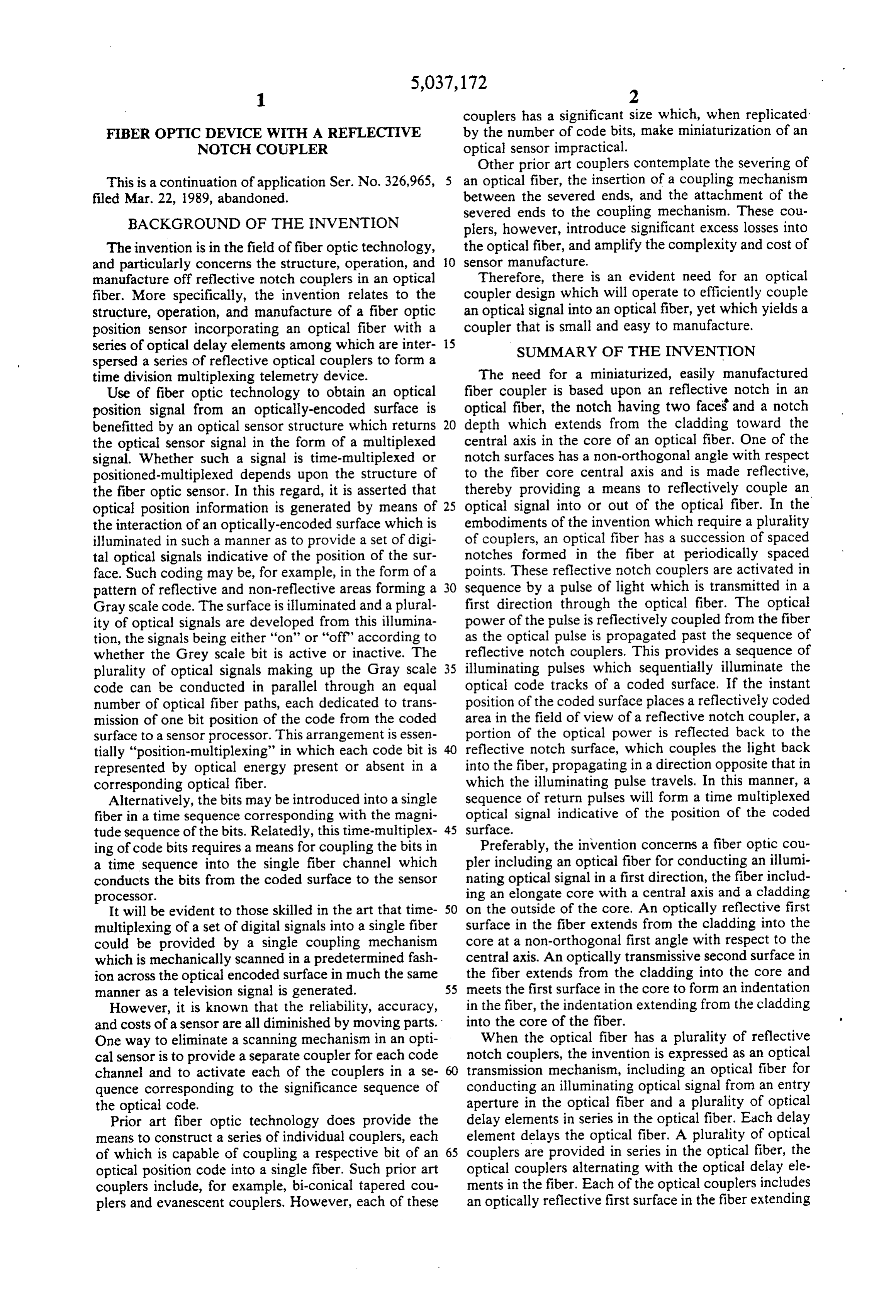
from the cladding into the core of the fiber. The first bi=2r arctan (2rhi-h;?)}/(r-hi)}; surface has a non-orthogonal first angle with respect to and wherein C is related to Ci- by: the central axis. The coupler further includes an opti cally transmissive second surface in the fiber extending Ci-1) from the cladding to the core, the second surface meet C =e
ing the first surface in the core to form an indentation in the fiber, the indentation extending from the cladding into the core of the fiber. O
h a = some
Last, the invention includes an optical read head for t 2 DE2C reading optical signals from an optically-encoded sur O face, the optically encoded surface including a plurality where D & E are delay line & excess losses, respec of substantially parallel (straight/circular) code tracks tively, and, last, forming an optically reflective surface in each of which an optical code is represented by opti on the first surface of each notch. cally reflective surface portions alternating with opti The primary objective of this invention is to provide cally non-reflective surface portions. The optical read 15 a miniaturized mechanism which will efficiently and head includes a carrier piece which is planar or has a effectively couple light into and out of an optical fiber. plurality of alignment grooves that are disposed in an A further objective of this invention is to provide a arrangement corresponding to the coding tracks. The method for manufacture of a miniaturized coupler read head further includes a single fiber coiled into an which effectively and efficiently couples light into and elongate cylinder in which a plurality of fiber loops are 20 out of an optical fiber.
extended out from the cylinder, each of the fiber loops These objects and other objects and distinct advan being attached to the carrier by being held in a respec tages of the invention will become evident when the tive one of the alignment grooves by special glass following description is read with reference to the be /ceramic bonding technology. An optical coupler is 25 low-described drawings.
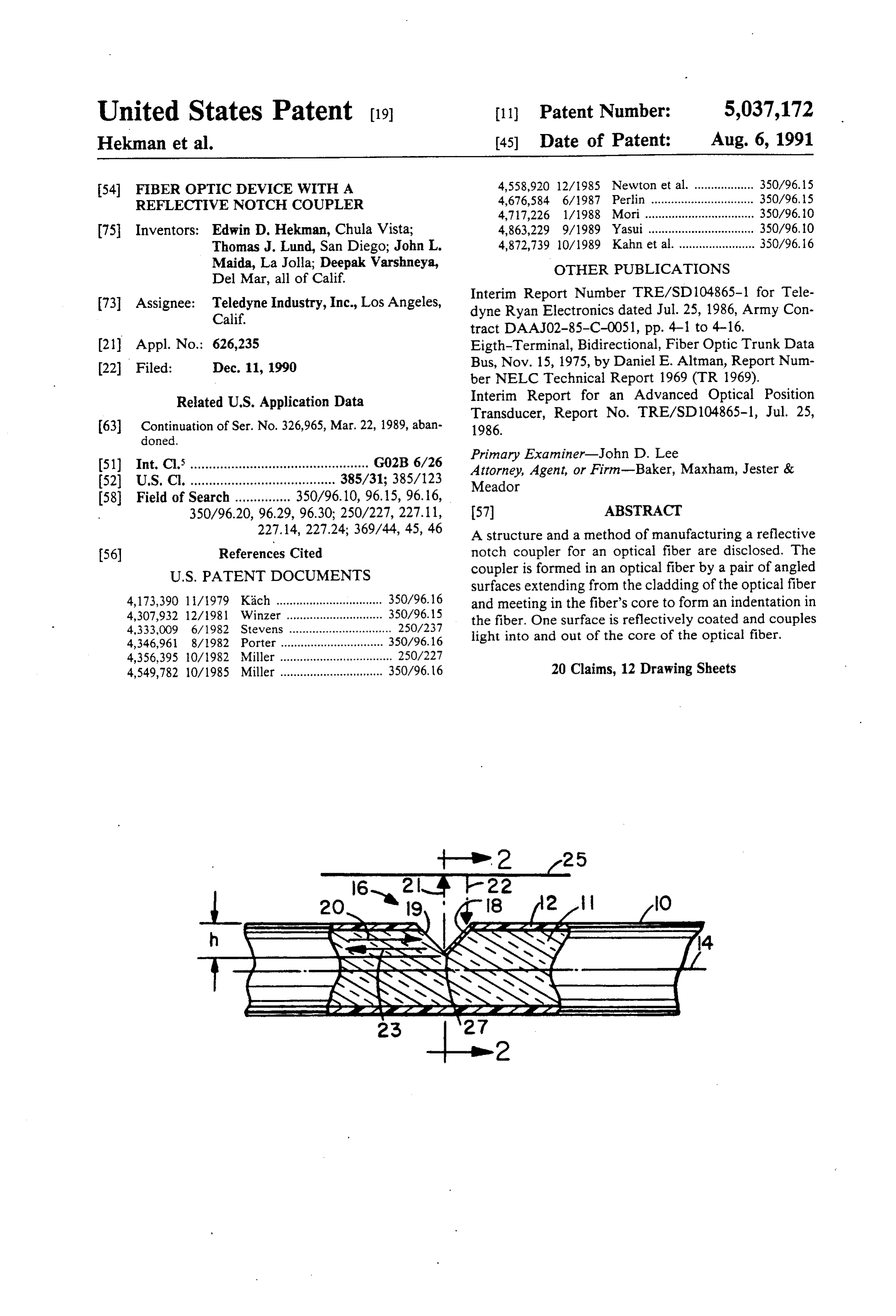
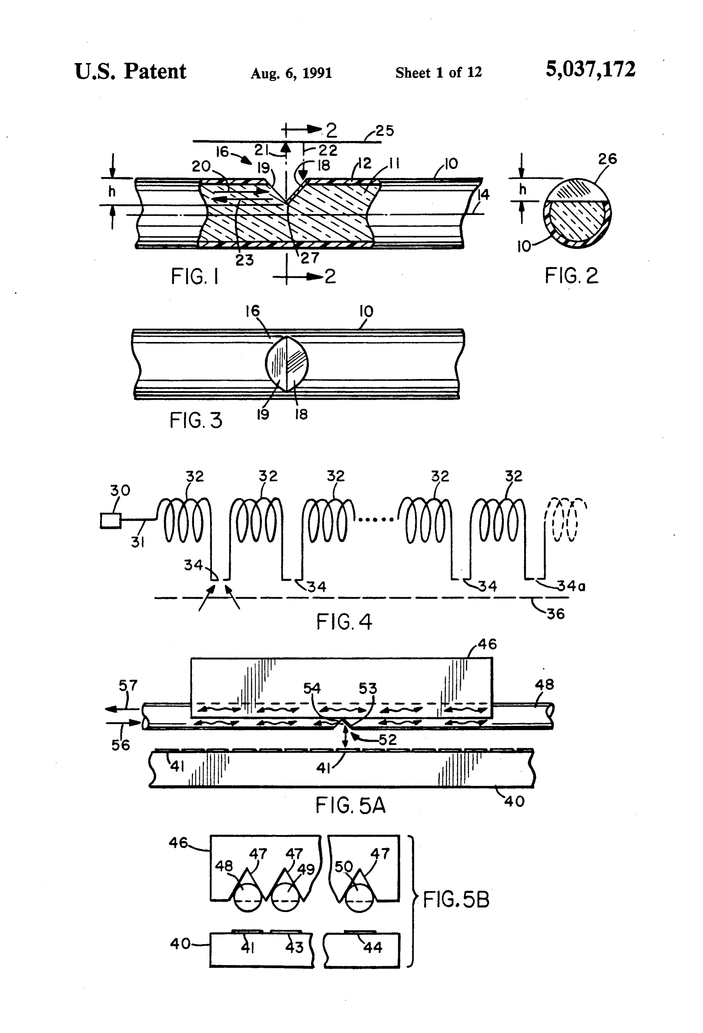
provided in each of the fiber loops at a location on the carrier adjacent the respective groove in which the BRIEF DESCRIPTION OF THE DRAWINGS fiber loop is held. Each of the optical couplers includes FIG. 1 is a magnified side sectional view of an optical an optically encoded reflective first surface in the fiber fiber in which a reflective notch coupler has been extending from the cladding into the core, the optically formed according to the invention. reflective surface having a non-orthogonal first angle FIG. 2 is a circular sectional area projected by the with respect to the central axis of the fiber core. The reflective notch coupler of FIG. 1. coupler further includes an optically transmissive sec FIG. 3 is a magnified top view of the optical fiber of ond surface in the fiber extending from the cladding to FIG. 1 with the reflective notch coupler of the inven the core, the second surface meeting the first surface in 35 tion.
the core to form an indentation in the fiber, the indenta FIG. 4 is a schematic representation of a fiber optic tion extending from the cladding into the core of the position sensor which incorporates the reflective notch fiber. coupler of the invention.
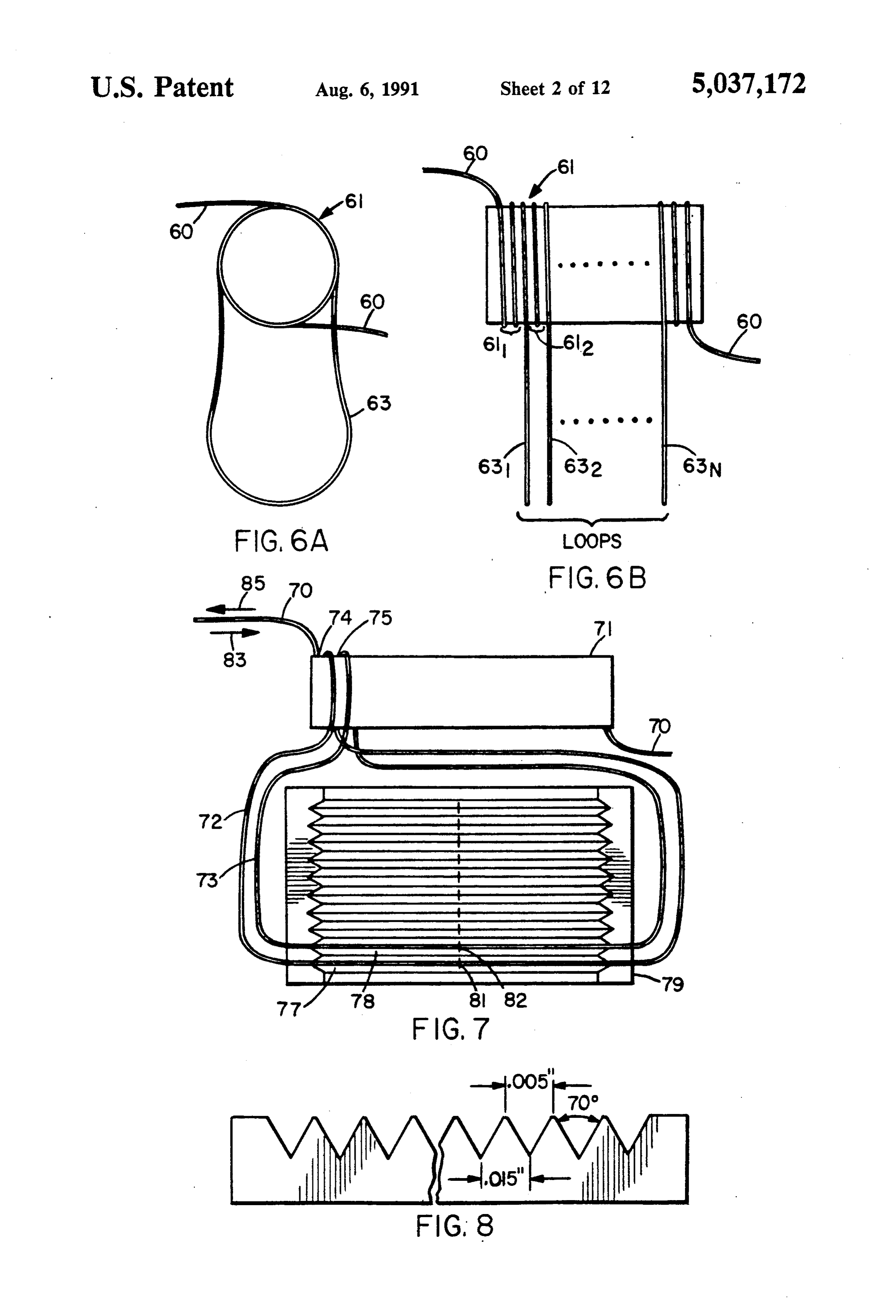
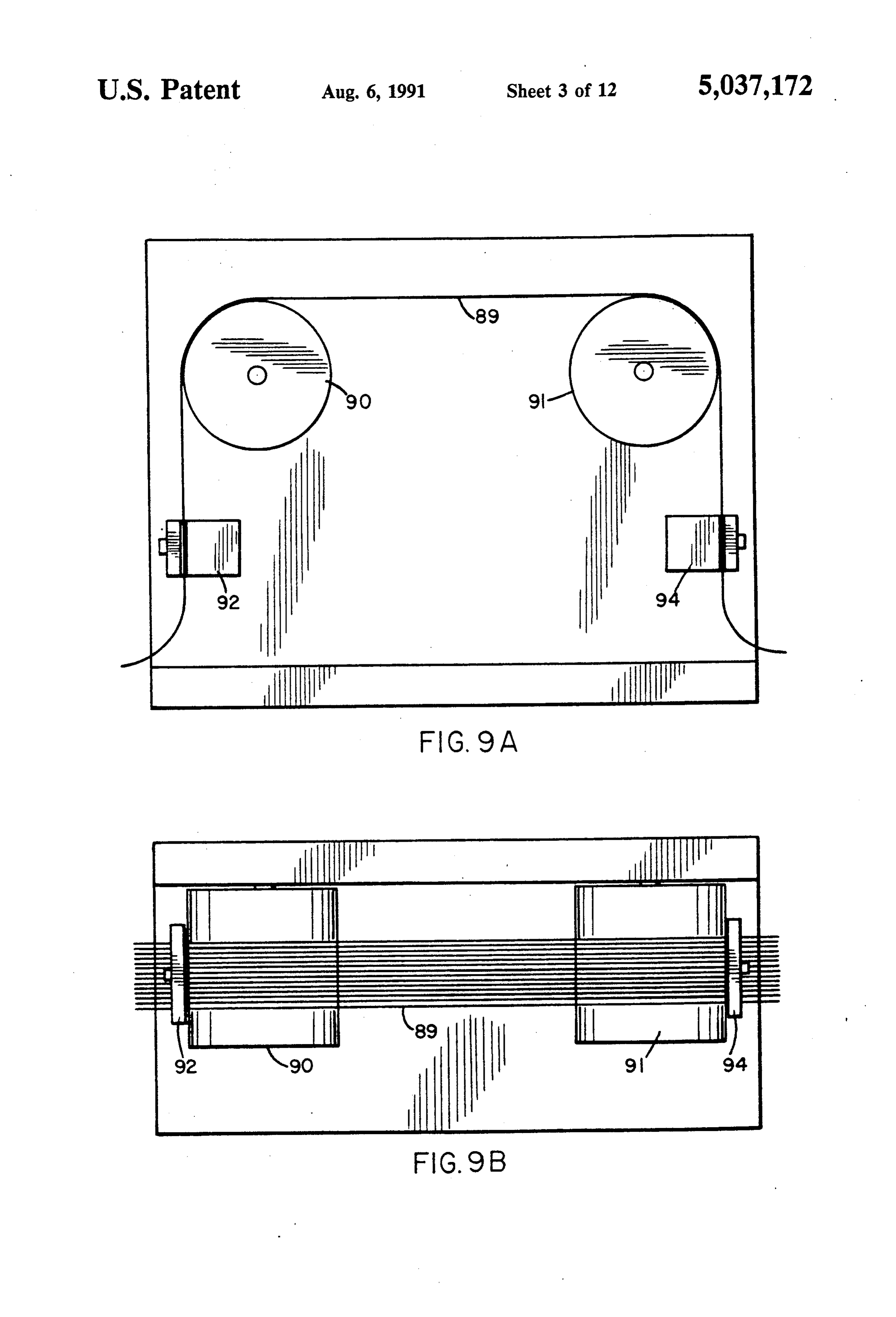
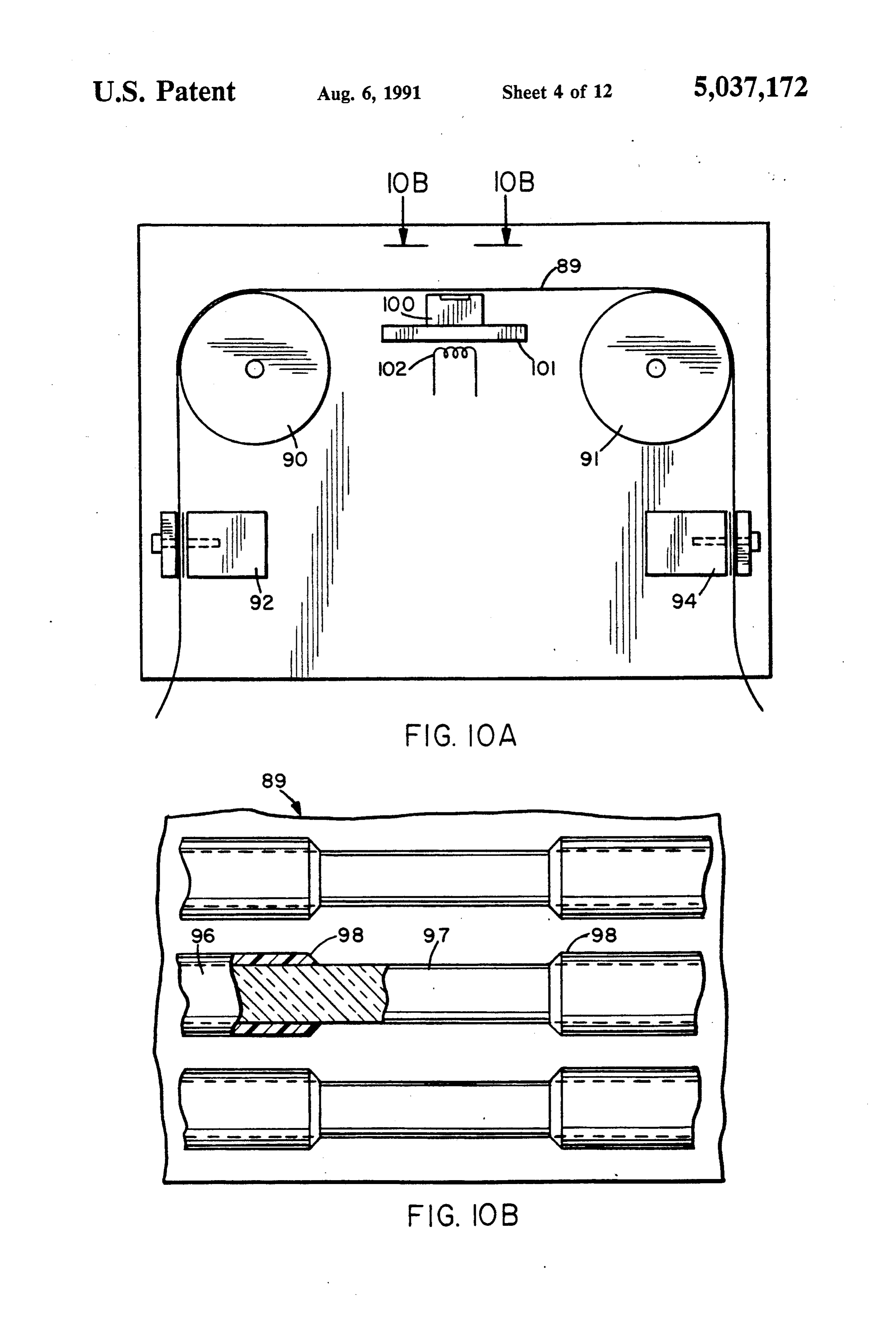
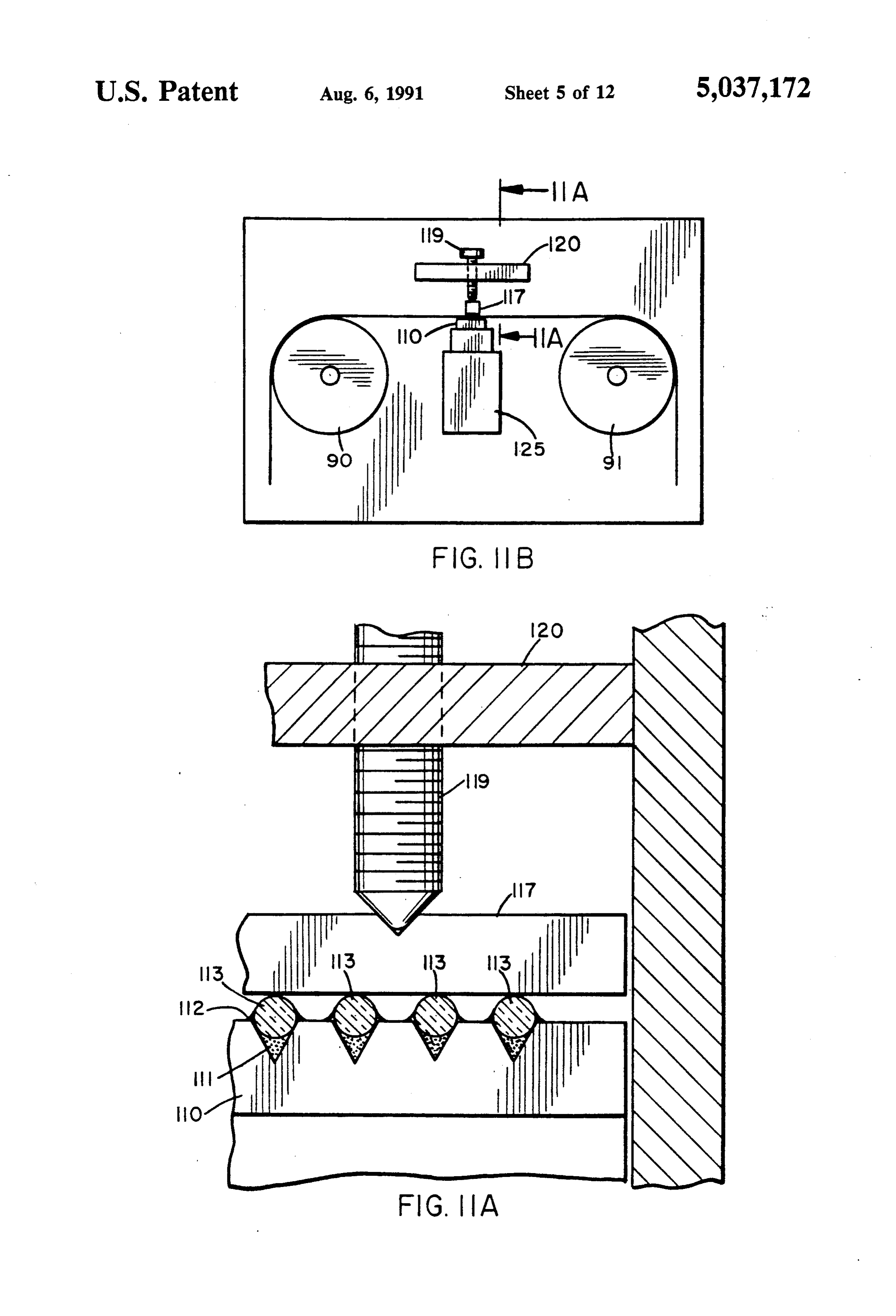
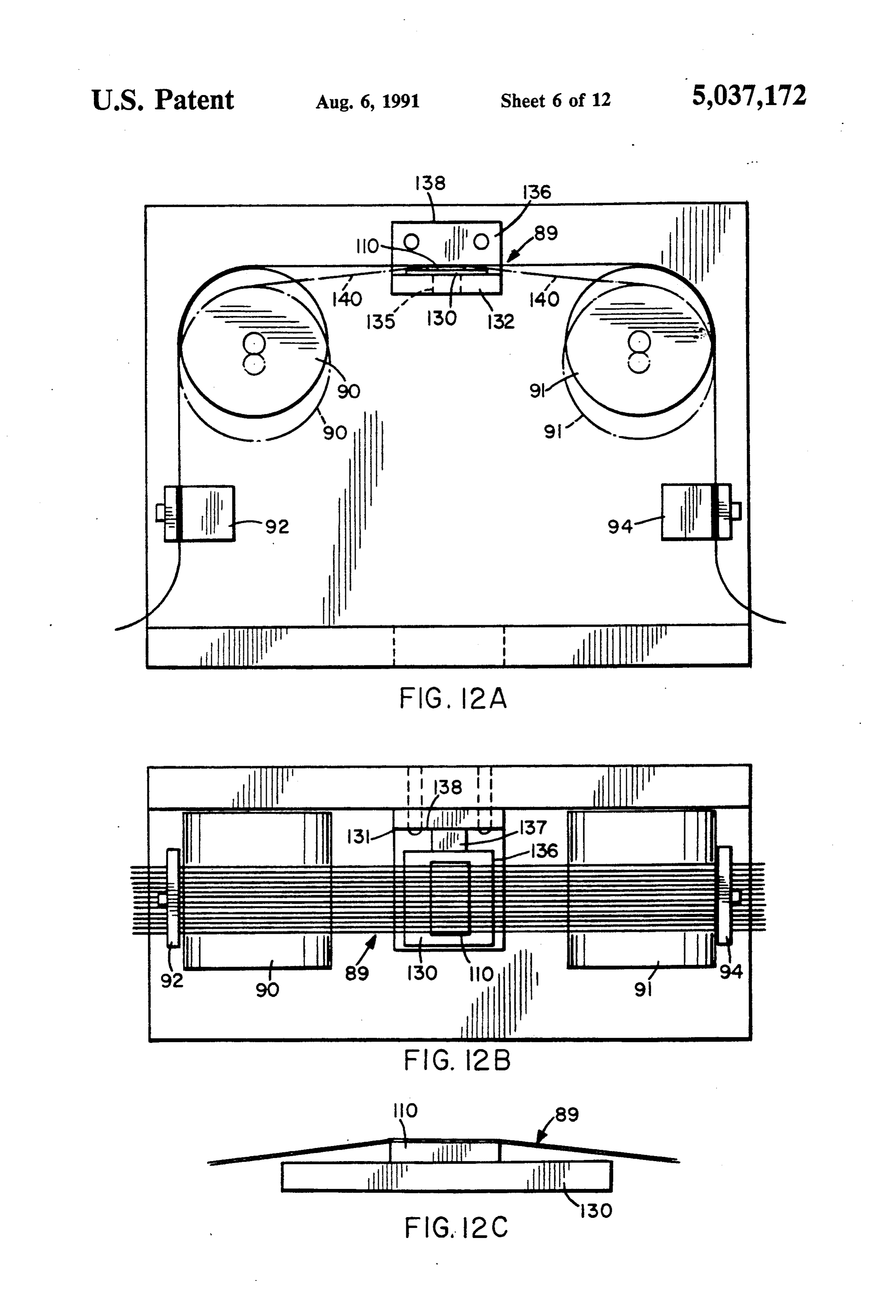
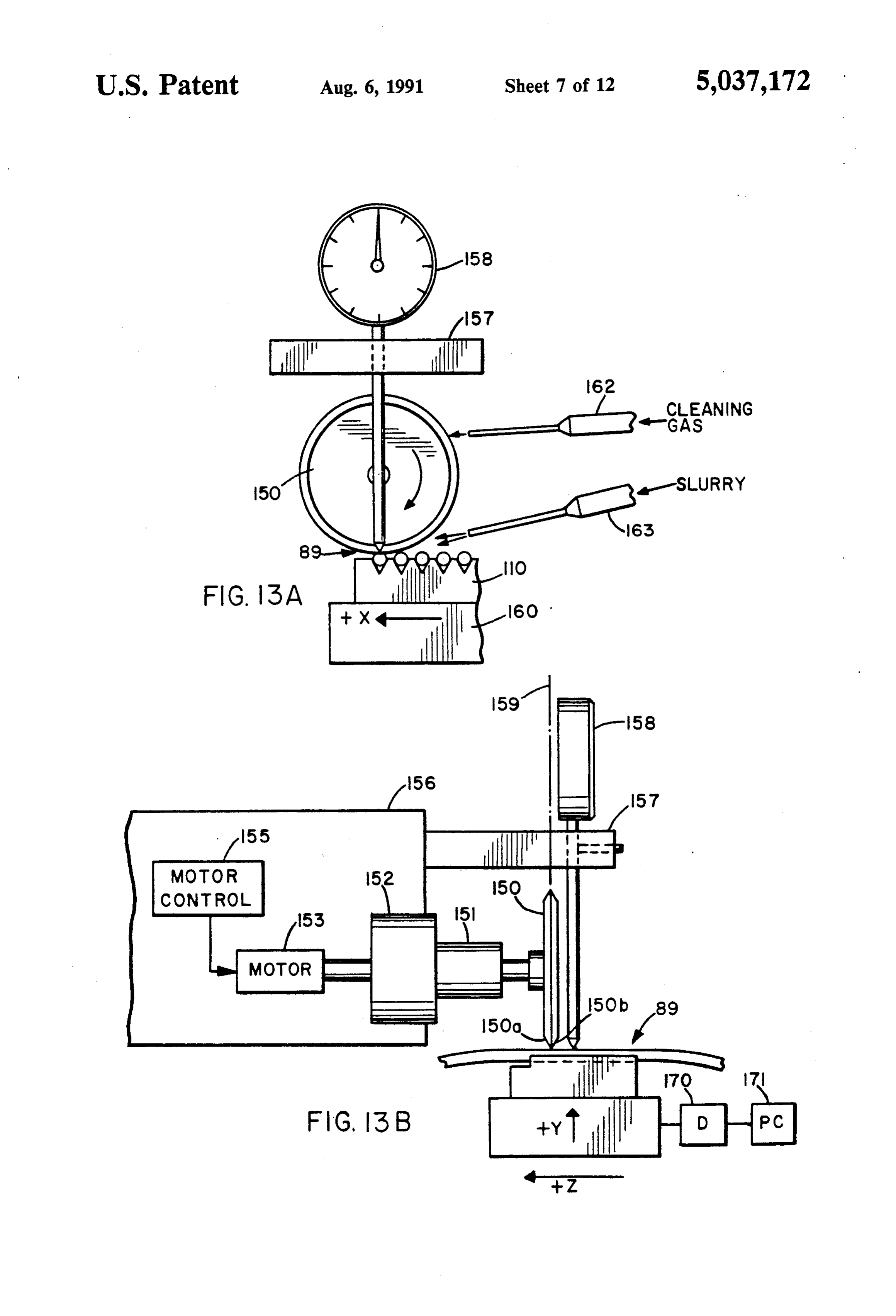
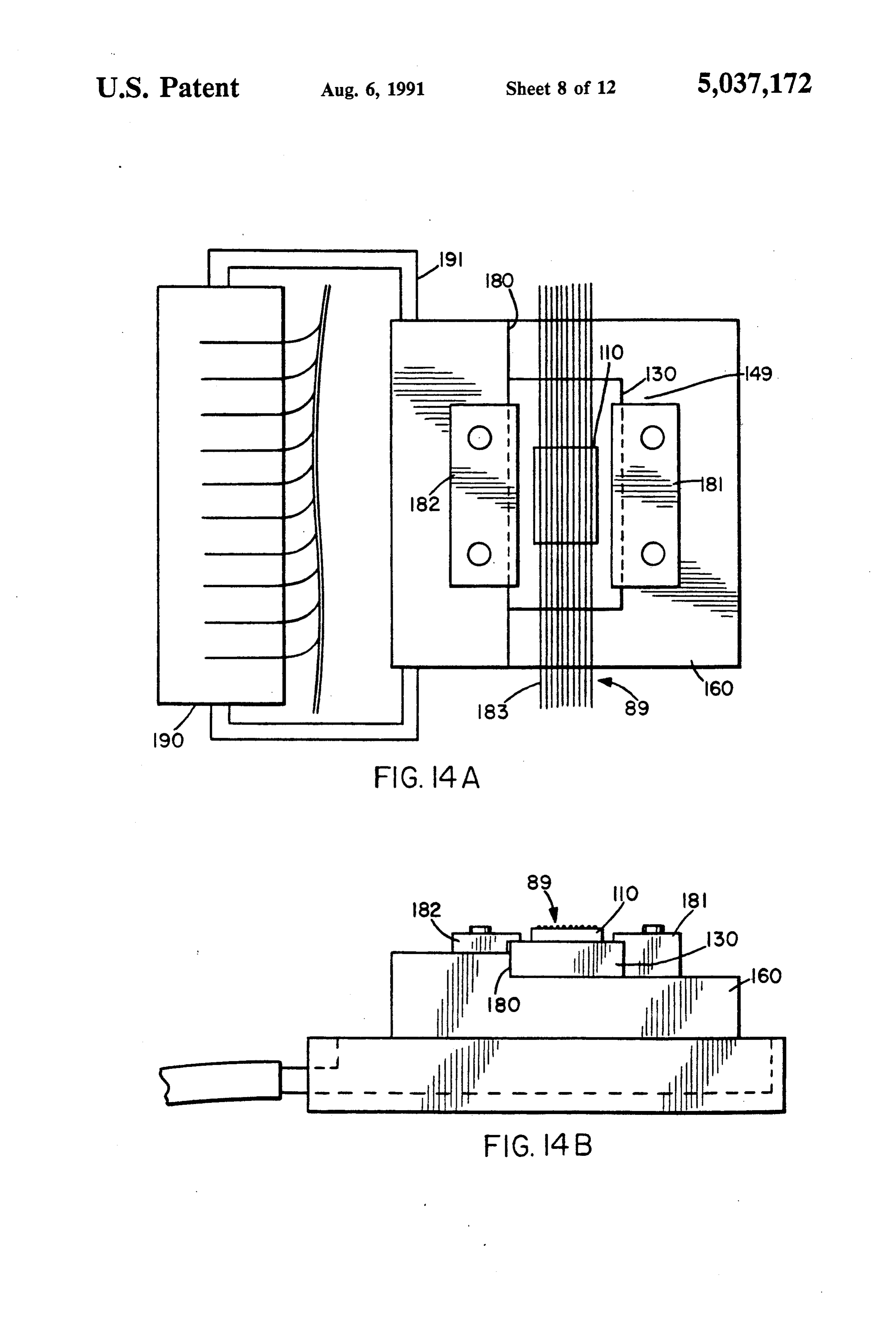
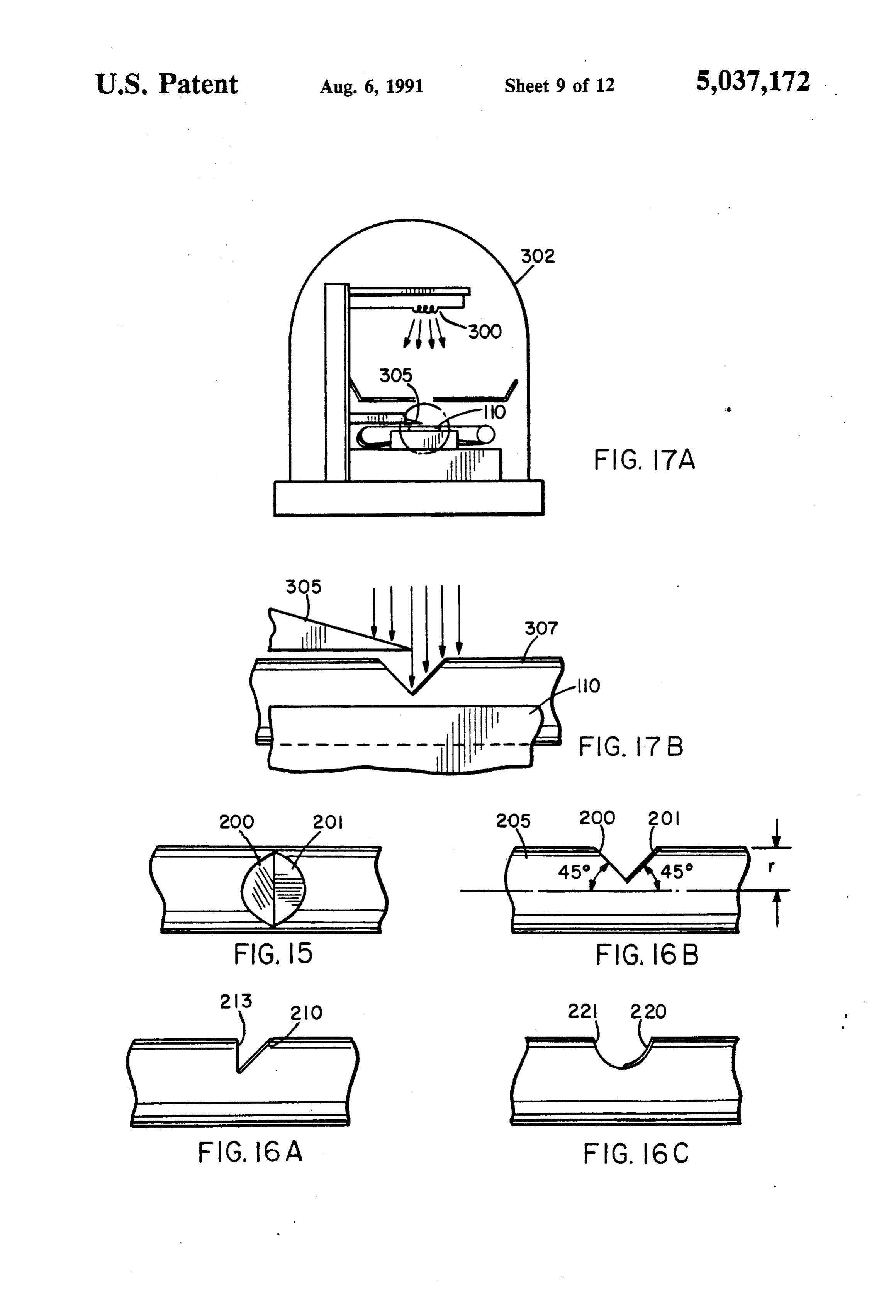
The invention includes the method of manufacturing FIGS. 5A and 5B are schematic representations of an optical coupler in an optical fiber, the optical fiber the mechanical configuration of a portion of a fiber including a core with a central axis and cladding applied optic read head incorporating the principles of FIGS. to the core. The method includes the steps of forming a 1-4 and the reflective notch coupler of the invention. notch in the optical fiber, the notch extending through FIGS. 6A and 6B are, respectively, the front and side the cladding into the core of the optical fiber. The notch views of a coiled optical fiber with extending loops. includes a first and a second surface, the first surface 45 FIG. 7 illustrates the basic components of the fiber having a non-orthogonal angle with respect to the cen optic read head utilizing a reflective notch coupler and tral axis. Last, an optically reflective material is at including the coiled optical fiber of FIGS. 6A and 6B tached to substantially all of the first surface. and a grooved silicon carrier. The invention is further expressed as a method of FIG. 8 is view from the front illustrating grooves in manufacturing a plurality of optical couplers in a single 50 the silicon carrier of FIG. 7. optical fiber, the optical fiber including a core with a FIGS. 9A-14B illustrate a sequence of steps in a radius r and a central axis, and cladding applied to the procedure for manufacturing an optical fiber read head core. The method includes the steps of arranging the which includes forming one or more reflective notch optical fiber into Nelongate, substantially parallel sec couplers in an optical fiber. tions. Then, in each of the N sections, a notch is formed 55 FIGS. 15 and 16A-16C illustrate the morphology of for output coupling a portion C of light traveling in the a reflective notch coupler manufactured according to fiber, each notch extending through the cladding and the invention.
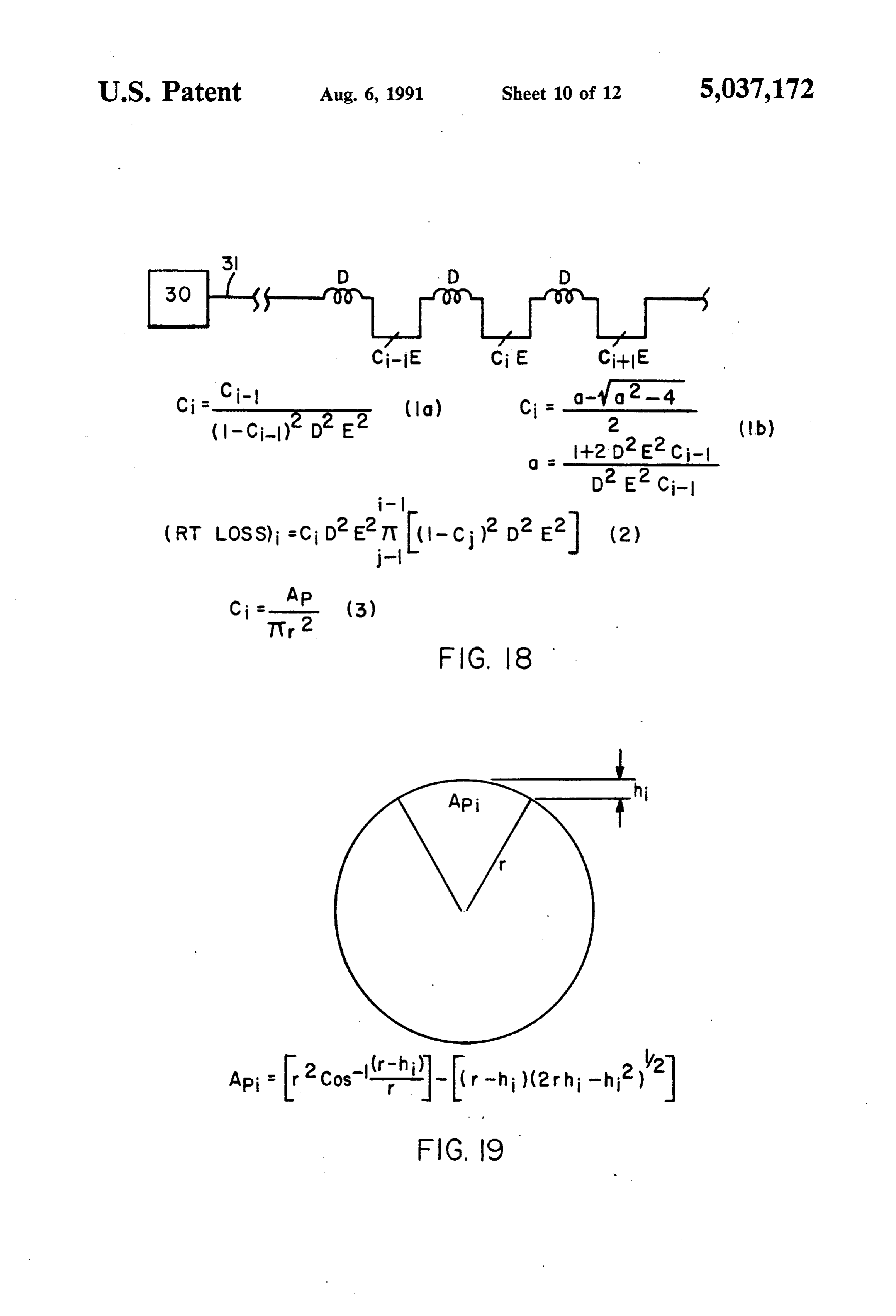
into the core of the optical fiber, and each notch includ FIGS. 17A-17B illustrate the method of applying ing a first surface and a second surface, the first surface reflective coating to the notches. having a non-orthogonal angle with respect to the cen FIG. 18 is a schematic representation and a set of tral axis. Last, in the ith section of the N sections, the mathematical relationships illustrating the interdepen step of forming the notch includes forming a notch dence of coupler operation and fiber geometry. having a depth hi, wherein: FIG. 19 is a geometrical and mathematical illustration of the interdependence of coupler operation and notch 65 height.
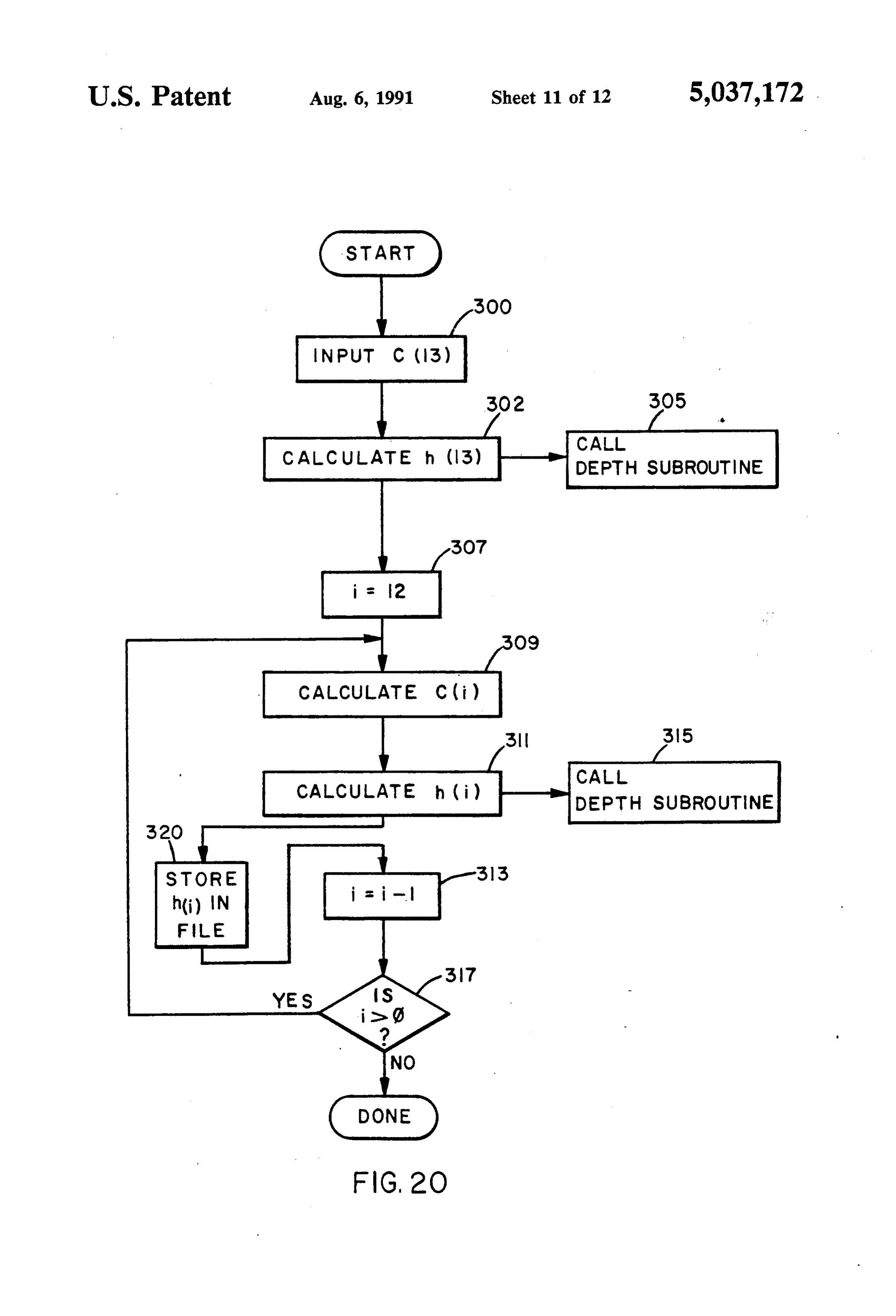
wherein: FIGS. 20-22 illustrate numerical procedure for deter pier {4(2hr O h2)}} mining the depths of a plurality of notches in a single and fiber of diameter r.
Page 16
delay element 32, a portion of the optical pulse is cou-.
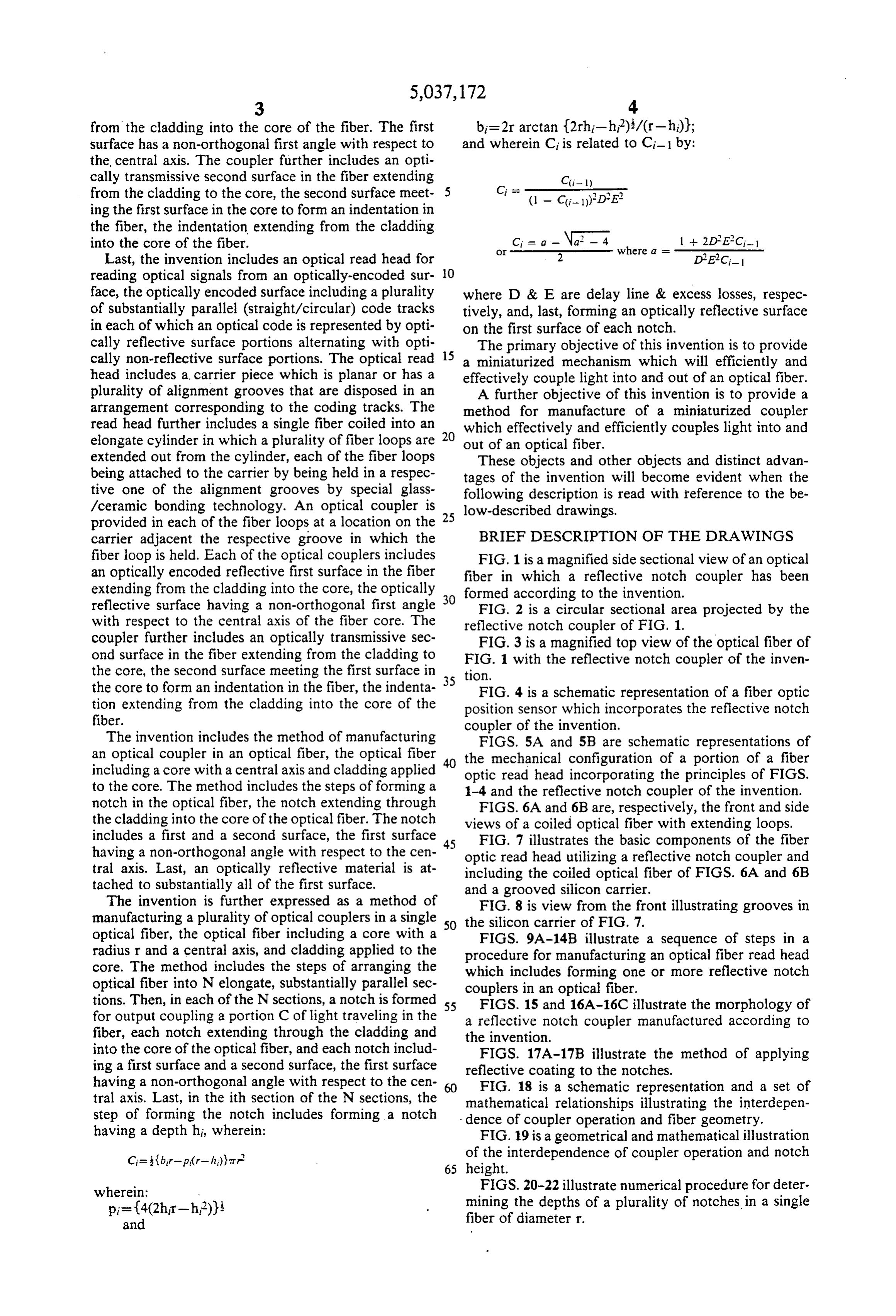
DETAILED DESCRIPTION OF THE pled out of the fiber onto the coded optical surface PREFERRED EMBODIMENTS through a reflective notch coupler. It is asserted that the In FIGS. 1 and 3, there is shown an optical fiber 10 surface at 36 is reflectively encoded. Thus, the optical including a fused silica core 11. The core 11 is sur code on the surface at 36 is rendered by the presence or rounded with a concentric cladding 12 which is doped absence of one or more reflective areas. The alternating to provide optical properties known to those skilled in reflective and non-reflective areas forming the code on the art. The fiber 10 has a generally elongate cylindrical the surface at 36 are formed into an array of parallel shape with a central axis 14. The properties of the fiber code tracks, each arranged to lie beneath a respective 10 enable it to conduct an optical signal (light) in either 10 one of the notch couplers 34. When the coded surface at of two directions in the core 11. A reflective notch 36 is fixed to a moving object, the arrangement of FIG. coupler according to the invention is indicated gener 4 becomes a position sensor, with the instant position of ally by 16 and includes a first surface 18 and second the object indicated by a unique set of reflective and surface 19. The first and second surfaces meet to form a non-reflective areas in the code tracks. generally V-shaped cross-section. In the invention, the 15 Returning to the description of the illuminating pulse, projection of the first surface 18 toward the central axis as the pulse passes each reflective notch 34, a portion of forms a non-orthogonal angle with the central axis 14. its optical power is coupled out of the fiber 31 onto the The first surface 18 is mirrored and is fully reflective of coded surface at 36. If the portion of the surface under light which is conducted in the core of the fiber 10. The lying the reflective notch coupler has a reflective area, second surface 19 is fully transmissive. 20 the portion of the illuminating light is reflected back to In operation, the coupler illustrated in FIG. 1 oper the notch coupler and thereby into the optical fiber 31. ates as follows. Light traveling in the direction indi Since the notch coupler couples energy out of the fiber cated by the arrow 20 in the fiber 10 is transmitted from a pulse, a pulse is reflected back from the coded through the second surface 19 onto the mirrored surface surface and into the fiber 31 in the form of a pulse. It 18 and is reflected (coupled) thereby from the fiber in 25 will be evident that, as the illuminating pulse propagates the direction of the broken arrow 21. Light from a from the transceiver 30 toward tho last reflective notch source internal/external to the fiber 10 and propagating coupler 34a, a series of reflected pulses would be propa toward the mirrored surface 18 in the direction indi cated by the broken line 22 is reflected by the surface 18 gated in the opposite direction toward the transceiver through the surface 19 into the fiber, where it is con minimum pulses 30 30. These are referred to as "return" pulses. The separation in time between any two of the ducted in the direction indicated by the arrow 23. Thus, return pulses is equivalent to the minimum propagation the reflective notch coupler 16 operates to couple light time through a delay element.
into and out of the fiber 10. Since the fiber 10 has a The return pulses propagate through the fiber to the generally cylindrical shape, the image projected by the optical transceiver 30, which couples them out of the mirrored surface 18 onto a surface located at 25 is an 35 area having the shape of a circular section 26, as indi fiber 31 and provides them for processing. The reflective surface of the notch filter can be wave cated in FIG. 2. The height h of the section 26 in FIG. length selective so that light in a certain frequency 2 corresponds to the height h of the notch 16 in FIG. 1. range would
The reflective notch coupler of FIGS. 1-3 is em reflect light inbethatcoupled range.
only from couplers which ployed usefully in an optical fiber sensor illustrated schematically in FIG. 4. In FIG. 4, an optical trans theAsensor physical embodiment of the fiber optic portion of schematically illustrated in FIG. 4 is illus ceiver transmits light into, and receives light fron, an trated in FIGS. 5A-7. In FIGS. 5A and 5B, a reflective optical fiber 31. A series of optical delay elements 32 are encoder 40 includes a plurality of optically encoded provided in the optical fiber 31. In practice, the delay code tracks. Each code track comprises a sequence of elements 32 are excess lengths of the fiber 31, which are 45 reflective and non-reflective areas, all the code tracks illustrated in FIG. 4 as coils. Each of the coils imposes a delay on the propagation of light represented by the together forming a position code such as a Grey scale time required for the light to travel through the excess code. In FIG. 5A, one code track includes a series of length of the coil. Also provided in the optical fiber 31 code reflective portions, two indicated by 41. In FIG. 5B, the is a series of reflective notch couplers 34. As FIG. 4 50 track of FIG. 5A is illustrated at the left-hand side illustrates, the notch couplers 34 are alternated with the of the reflective encoder 40, two other tracks being delay elements 32 so that light propagating in the fiber indicated by reflective portions 43 and 44. A block 46 positions a plurality of reflective notch 31 from the transceiver 30 encounters a reflective notch coupler 34 immediately after one of the delay elements couplers formed in an optical fiber such that each re flective notch coupler is oriented to face a respective 32. It will be appreciated that the fiber optic sensor of 55 one
FIG. 4 comprises a single optical fiber in which the of the code tracks on the encoder 40. The block 46 coils and reflective notch filters (which can be wave includes a series of parallel, elongate grooves 47, each length selective) are integral elements. groove for receiving and positioning a section of the The fiber of FIG. 4 is enabled to operate as a sensor optical fiber. The sections are indicated, respectively, by provision of a coded optical surface at location 36, 60 by 48, 49, and 50. A reflective notch coupler is formed and orientation of the reflective notch couplers 34 to in each of the sections 48, 49, and 50 with the orienta face the encoded surface. The arrangement of FIG. 4 tion illustrated in FIG. 5A. In FIG. 5A, the reflective operates by decoupling and recoupling time-delayed notch 52 includes a reflective surface 53 and a transmis optical pulses across the continuous optical fiber 31. In sive surface 54. In this orientation, an illuminating pulse this regard, an illuminating optical pulse is injected into 65 is transmitted through the fiber so that it travels in the the fiber 31 from the transceiver 30 and propagates section 48 in the direction indicated by the arrow 56. If through the fiber 31 from the transceiver 30 toward the the present position of the encoder 40 positions a reflec reflective notch coupler 34a. After passing through a tive portion 41 beneath the coupler 52, a return pulse
Page 17
will be coupled into the fiber section 48 propagating in meters of any one of the coil sections and i=1,2,3,... the direction indicated by the arrow 57. s N.
Refer now to FIGS.6A and 6B for an understanding METHOD OF FABRICATION of an embodiment which incorporates the fiber sections of FIGS. 5A and 5B and the delay elements of FIG. 4 Next, the method of manufacturing a fiber optic read into a single optical fiber. In FIGS. 6A and 6B, a single head as described above will be laid out, with particular fiber 60 is conventionally formed into a helically wound emphasis on computer numerical control (CNC) for coil 61. Intermittently, a long loop of the fiber 60 is forming reflective notch couplers. In the preferred en extended from the coil 61, one of the loops 63 being bodiment, the method produces reflective notches in illustrated in FIG. 6A as depending from the coil 61. As O which each notch surface has a non-orthonogal angle of shown in FIG. 6B, N elongate loops 631-63N are approximately 45 degrees with respect to the central formed.
As FIG. 6B shows, each of the loops 631-63N is pre axisInitially, of the fiber in which the notches are being formed.
a predetermined length of optical fiber is ceded by a section of coil, two sections being indicated used, for example, 30 meters. The fiber is, preferably, a by 611 and 612. In the preferred embodiment, the coil 15 glass-clad, glass silica fiber to which a concentric buffer sections 612-61N include equal lengths of the fiber 60. comprised of a non-silica material has been applied to Resultantly, the delay represented by each of the coil sections is equivalent to the delay represented by any impart strength, durability, and environmental surviv other coil section. ability to the fiber. Typically, the outside diameter of a . . Assembly of the fiber optic read head is illustrated in buffered fiber is 0.005 inches, or 127 microns. The over FIG. 7. In FIG. 7, an optical fiber 70 is formed into a all diameter of the unbuffered fiber is 110 microns, with coil 71 with extending loops 72 and 73 alternating with the diameter of the core being 100 microns. Such fibers coil delay sections 74 and 75. The loops 72 and 73 are are "off-the-shelf'.
held in grooves 77 and 78, respectively, which are Fabrication of the fiber optic read head begins with formed in a carrier 79. Reflective notch couplers 81 and 25 winding the buffered fiber on a mandrel of predeter 82 are formed in the loops 72 and 73, respectively. With mined diameter in the matter illustrated in FIGS. 6A this configuration, the block 79 can be oriented with and 6B to provide a fiber coil of predetermined diame respect to a reflective encoder, with each of the reflec ter in which N extended loops alternate with N coil tive notches facing a respective code tract of the en sections of equal size.
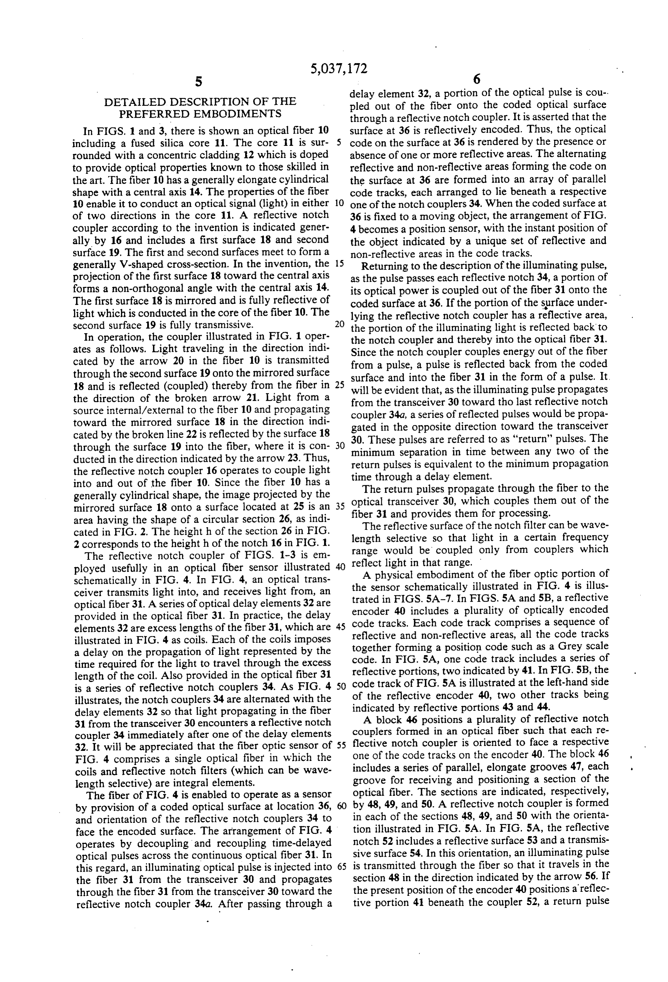
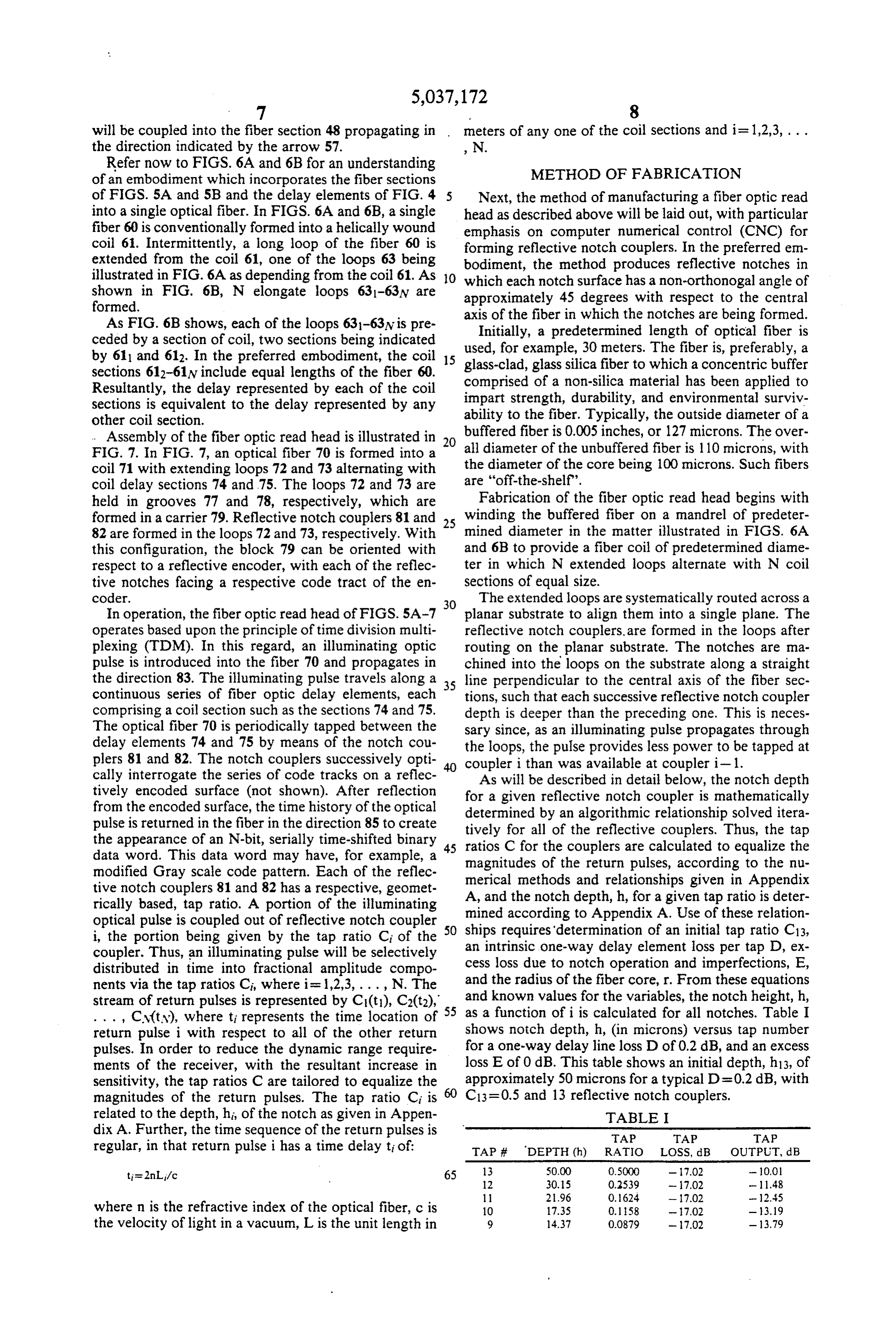
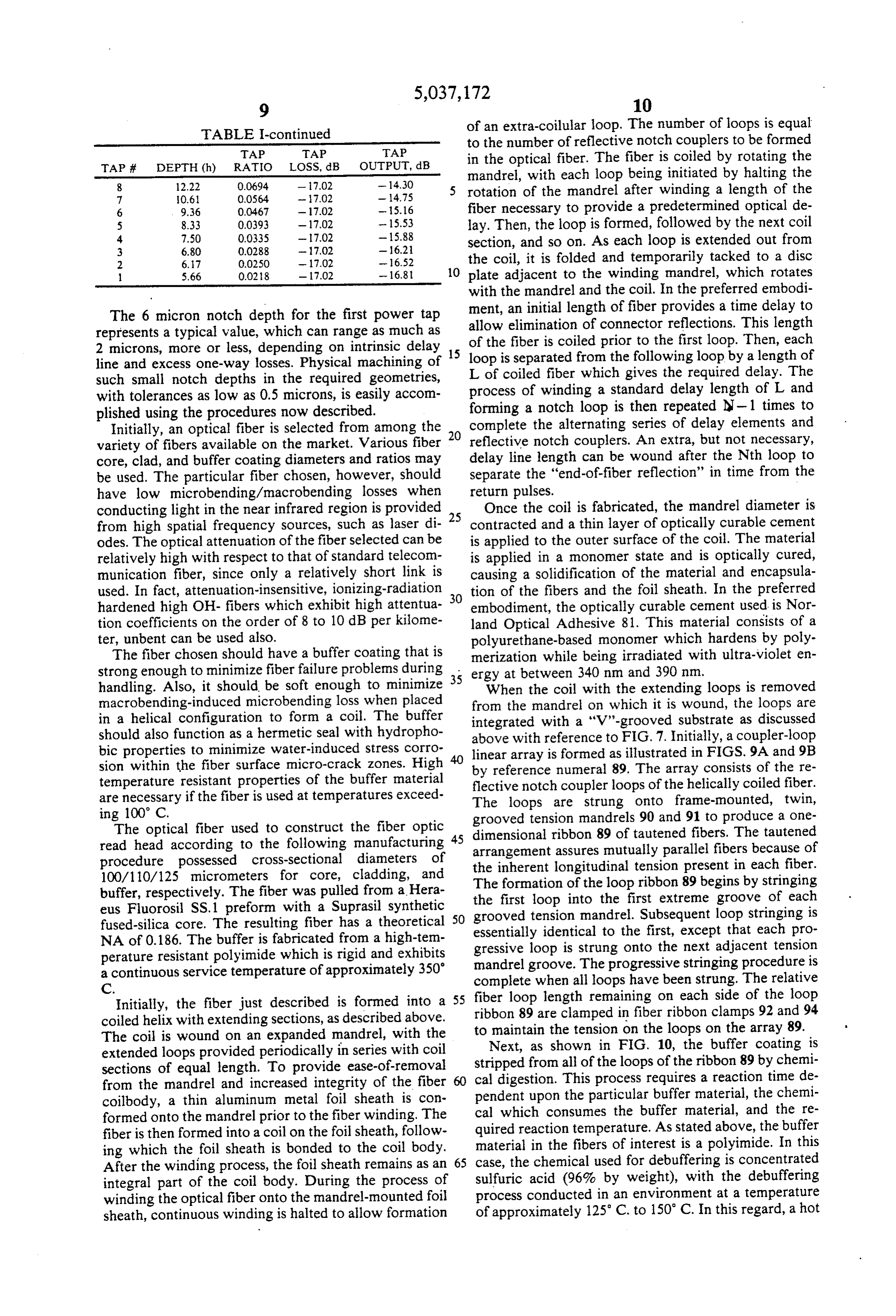
coder. 30 The extended loops are systematically routed across a In operation, the fiber optic read head of FIGS. 5A-7 planar substrate to align them into a single plane. The operates based upon the principle of time division multi reflective notch couplers. are formed in the loops after plexing (TDM). In this regard, an illuminating optic routing on the planar substrate. The notches are ma pulse is introduced into the fiber 70 and propagates in chined into the loops on the substrate along a straight the direction 83. The illuminating pulse travels along a 35 line perpendicular to the central axis of the fiber sec continuous series of fiber optic delay elements, each tions, such that each successive reflective notch coupler comprising a coil section such as the sections 74 and 75. depth is deeper than the preceding one. This is neces The optical fiber 70 is periodically tapped between the sary since, as an illuminating pulse propagates through delay elements 74 and 75 by means of the notch cou the loops, the pulse provides less power to be tapped at plers 81 and 82. The notch couplers successively opti coupler i than was available at coupler i-l. cally interrogate the series of code tracks on a reflec As will be described in detail below, the notch depth tively encoded surface (not shown). After reflection for a given reflective notch coupler is mathematically from the encoded surface, the time history of the optical determined by an algorithmic relationship solved itera pulse is returned in the fiber in the direction 85 to create tively for all of the reflective couplers. Thus, the tap the appearance of an N-bit, serially time-shifted binary 45 ratios C for the couplers are calculated to equalize the data word. This data word may have, for example, a modified Gray scale code pattern. Each of the reflec magnitudes of the return pulses, according to the nu merical methods and relationships given in Appendix tive notch couplers 81 and 82 has a respective, geomet A, and the notch depth, h, for a given tap ratio is deter rically based, tap ratio. A portion of the illuminating optical pulse is coupled out of reflective notch coupler 50 mined ships according to Appendix A. Use of these relation requires "determination of an initial tap ratio C13, i, the portion being given by the tap ratio C of the an intrinsic one-way delay element loss per tap D, ex coupler. Thus, an illuminating pulse will be selectively distributed in time into fractional amplitude compo cess loss due to notch operation and imperfections, E, nents via the tap ratios Ci, where is 1,2,3,..., N. The and the radius of the fiber core, r. From these equations stream of return pulses is represented by C(t), C(t), 55 and known values for the variables, the notch height, h, . . . , Cy(tA), where ti represents the time location of as a function of i is calculated for all notches. Table I return pulse i with respect to all of the other return shows notch depth, h, (in microns) versus tap number pulses. In order to reduce the dynamic range require for a one-way delay line loss D of 0.2 dB, and an excess ments of the receiver, with the resultant increase in loss E of 0 dB. This table shows an initial depth, hi5, of sensitivity, the tap ratios C are tailored to equalize the approximately 50 microns for a typical D=0.2 dB, with magnitudes of the return pulses. The tap ratio Ci is C13=0.5 and 13 reflective notch couplers. related to the depth, hi, of the notch as given in Appen TABLE I dix A. Further, the time sequence of the return pulses is TAP TAP TAP regular, in that return pulse i has a time delay ti of: TAP # DEPTH (h) RATIO LOSS, dB OUTPUT, dB
where n is the refractive index of the optical fiber, c is 10 17.35 0.158 - 7.02 - 3.19 the velocity of light in a vacuum, L is the unit length in 9 1437 0.0879 - 7.02 - 13.79
Page 18
TABLE I-continued of an extra-coilular loop. The number of loops is equal
to the number of reflective notch couplers to be formed
TAP # DEPTH (h) RATIO LOSS, dB OUTPUT, dB in the optical fiber. The fiber is coiled by rotating the
mandrel, with each loop being initiated by halting the 7 0.61 0.0564 - 17.02 - 14.75 rotation of the mandrel after winding a length of the 6 9.36 0.0467 - 7.02 - 5.16 fiber necessary to provide a predetermined optical de
lay. Then, the loop is formed, followed by the next coil
section, and so on. As each loop is extended out from 2 6.17 0.0250 - 17.02 - 16.52 the coil, it is folded and temporarily tacked to a disc 1 5,66 0.028 - 17.02 - 16.81 10 plate adjacent to the winding mandrel, which rotates with the mandrel and the coil. In the preferred embodi
The 6 micron notch depth for the first power tap ment, an initial length of fiber provides a time delay to represents a typical value, which can range as much as of the elimination allow of connector reflections. This length 2 microns, more or less, depending on intrinsic delay 15 loop is separated fromprior fiber is coiled to the first loop. Then, each line and excess one-way losses. Physical machining of L of coiled fiber whichthegives following loop by a length of such small notch depths in the required geometries, process of winding a standardthe required delay. The with tolerances as low as 0.5 microns, is easily accom forming a notch loop is then repeatedlength delay
of L and times to plished using the procedures now described.
Initially, an optical fiber is selected from among the 20 complete the alternating series of delay elements and variety of fibers available on the market. Various fiber reflective notch couplers. An extra, but not necessary, core, clad, and buffer coating diameters and ratios may delay line length can be wound after the Nth loop to be used. The particular fiber chosen, however, should separate the "end-of-fiber reflection' in time from the have low microbending/macrobending losses when return pulses.
conducting light in the near infrared region is provided 25 Once the coil is fabricated, the mandrel diameter is from high spatial frequency sources, such as laser di contracted and a thin layer of optically curable cement odes. The optical attenuation of the fiber selected can be is applied to the outer surface of the coil. The material relatively high with respect to that of standard telecom is applied in a monomer state and is optically cured, munication fiber, since only a relatively short link is causing a solidification of the material and encapsula used. In fact, attenuation-insensitive, ionizing-radiation tion of the fibers and the foil sheath. In the preferred hardened high OH- fibers which exhibit high attentua 30 embodiment, the optically curable cement used is Nor tion coefficients on the order of 8 to 10 dB per kilome land Optical Adhesive 81. This material consists of a ter, unbent can be used also. polyurethane-based monomer which hardens by poly The fiber chosen should have a buffer coating that is merization while being irradiated with ultra-violet en strong enough to minimize fiber failure problems during 35 ergy at between 340 nm and 390 nm. handling. Also, it should be soft enough to minimize When the coil with the extending loops is removed macrobending-induced microbending loss when placed from the mandrel on which it is wound, the loops are in a helical configuration to form a coil. The buffer integrated with a "V"-grooved substrate as discussed should also function as a hermetic seal with hydropho above with reference to FIG. 7. Initially, a coupler-loop bic properties to minimize water-induced stress corro linear array is formed as illustrated in FIGS. 9A and 9B sion within the fiber surface micro-crack zones. High by reference numeral 89. The array consists of the re temperature resistant properties of the buffer material flective notch coupler loops of the helically coiled fiber. are necessary if the fiber is used at temperatures exceed The loops are strung onto frame-mounted, twin, ing 100 C. grooved tension mandrels 90 and 91 to produce a one The optical fiber used to construct the fiber optic 45 dimensional ribbon 89 of tautened fibers. The tautened read head according to the following manufacturing procedure possessed cross-sectional diameters of arrangement assures mutually parallel fibers because of 100/110/125 micrometers for core, cladding, and The formation of the looptension the inherent longitudinal present in each fiber.
buffer, respectively. The fiber was pulled from a Hera the first loop into the first extremebegins ribbon 89 by stringing groove of each eus Fluorosil SS.1 preform with a Suprasil synthetic 50 grooved tension mandrel. Subsequent loop stringing fused-silica core. The resulting fiber has a theoretical essentially identical to the first, except that each prois NA of 0.186. The buffer is fabricated from a high-tem gressive loop is strung onto the next adjacent tension perature resistant polyimide which is rigid and exhibits mandrel groove. The progressive stringing procedure is a continuous service temperature of approximately 350 complete when all loops have been strung. The relative
Initially, the fiber just described is formed into a 55 fiber loop length remaining on each side of the loop ribbon 89 are clamped in fiber ribbon clamps 92 and 94 coiled helix with extending sections, as described above. to maintain the tension on the loops on the array 89. The coil is wound on an expanded mandrel, with the Next, as shown in FIG. 10, the buffer coating is extended loops provided periodically in series with coil stripped from all of the loops of the ribbon 89 by chemi sections of equal length. To provide ease-of-removal cal digestion. This process requires a reaction time de from the mandrel and increased integrity of the fiber pendent upon the particular buffer material, the chemi coilbody, a thin aluminum metal foil sheath is con formed onto the mandrel prior to the fiber winding. The cal which consumes the buffer material, and the re fiber is then formed into a coil on the foil sheath, follow quired reaction temperature. As stated above, the buffer ing which the foil sheath is bonded to the coil body. material in the fibers of interest is a polyimide. In this After the winding process, the foil sheath remains as an 65 case, the chemical used for debuffering is concentrated integral part of the coil body. During the process of sulfuric acid (96% by weight), with the debuffering winding the optical fiber onto the mandrel-mounted foil process conducted in an environment at a temperature sheath, continuous winding is halted to allow formation of approximately 125 C. to 150 C. In this regard, a hot
Page 19
sulfuric acid bath is contained in a teflon tub 100 which so that it fills the grooves of the carrier in the bonding rests upon a stainless steel plate that conducts heat to mesa portion. The cement is delivered to the grooves by the sulfuric acid from a heating coil 102. As the acid a spatula/spackling technique. Excess cement is re temperature increases, its chemical reactivity increases moved along the bonding mesa surface 112, leaving the also. Thus speeding up the process of buffer digestion. cement filling in the V-grooves. The cement-filled sub The teflon tub has an aperture which faces the ribbon strate 110 is then positioned directly beneath the debuff array in an area referred to as the "bond region", which ered bonding area of the fiber ribbon 89 and centered. is magnified at the upper portion of FIG. 10. The result The fibers 113 of the array 89 are aligned with the V of the debuffering process can be understood with the grooves and seated in the grooves.
magnified portion of FIG. 10 by reference to an optical 10 Alignment of the debuffered bonding region of the fiber 96 from which the heated sulfuric acid has con fiber loop ribbon 89 with the grooves of the carrier sumed approximately 0.2 linear inches of buffer coating substrate 110 is accomplished by translating the sub 98 to expose the outer surface of the fiber cladding 97. strate with respect to the ribbon 89 in the x, y, and z All of the fibers in the ribbon 89 are similarly prepared directions by a micropositioner (not shown). After in the bond region by removal of their buffer coatings. 15 alignment, the fibers 113 are seated in the cement-filled The buffer region is contained in a relatively small grooves by use of a clamping pressure pad 117. The length of the taunted fiber optic loop array 89 which is pressure pad is applied directly to the top of the fiber centered between the twin tension mandrels 90 and 91. loop ribbon 89 in the bonding region and, after proper Next, a grooved substrate is formed conventionally out placement, it and the fibers are driven towards the of a silicon material according to the configurations for 20 bonding mesa surface 112 of the carrier substrate 110 by the carriers indicated by reference numeral 79 in FIG. 7 a pivot-type uniform force-inducing screw 119. The and reference numeral 46 in FIGS. 5A and 5B. Carrier screw threads through a stationary plate 120. In the substrate preparation is accomplished independently of arrangement of FIGS. 11A and 11B, all of the debuff the fiber preparation process and is primarily concerned ered fiber loop portions are simultaneously driven into with assuring that the axial (length) dimensions of the 25 the V-grooves and seat to the identically sloped sur grooves are correct, that sharp edges are deburred, and faces of the grooves. Seating of the fiber loop portions the all debris and oil are removed. In this process step, 113 displaces an amount of cement material 119 out of a silicon carrier substrate is prepared from a "mother' each V-groove. This displaced cement material is trans substrate having N V-shaped grooves cut into one sur ported to the bonding mesa surface in the region above face. As shown in FIG. 8, the groove faces are equilat 30 the edges of each V-groove where, through adhesive eral and meet at an angle of 70. Each groove's face and cohesive properties it maintains contact between a opening is approximately 0.005 inches, and the grooves fiber and the bonding mesa surface. This contact pro are spaced at 0.015 inches. From a "mother' substrate, vides lateral support, adding strength to the seating of a carrier substrate is cut. In the preferred embodiment, each fiber.
the carrier substrate is 0.333 inches long, 0.25 inches 35 Following alignment and seating of the debuffered wide, and 0.020 inches thick. A carrier is cut from a fiber loop portions in the V-grooves, the cement mate mother substrate by a high-powered frequency-doubled rial 111 is activated at a temperature exceeding its glass neodymium YAG laser. Laser vaporization is preferred transition temperature. The heating is provided by a for cutting carrier substrates since it leaves few burrs thermo-electric heater 125, which raises the ambient along the cut edges of the carrier and since subsequent temperature in the vicinity of the bonding mesa surface separation along a cut requires low stress. A carrier to 475 C, within a couple of minutes, this temperature substrate is finally prepared by subjecting it to an ultra being maintained for three minutes to drive off the or sonic vibration chamber filled with transistor grade ganic species in the cement. The bonding mesa surface acetone to sonically scrub and clean the V-grooved is then allowed to cool over a period of twenty minutes surface. The grooved surface of the substrate is referred 45 prior to proceeding to the next step. to as the “bonding mesa'. A supplementary support is attached to the under FIGS. 11A and 11B illustrate the step of attaching the surface of the carrier substrate in a procedure step illus bonding area of the fiber loop ribbon to the carrier trated in FIGS. 12A-12C. A transparent glass plate 130 substrate. In order to bond the exposed silica glass fiber is attached to the bottom surface of the carrier substrate loops to the grooves of the carrier substrate, an interme 50 110 by an organic epoxy which cures upon exposure to diate material is necessary. This material is a bonding UV radiation. The glass plate is transparent in order to agent which exhibits thermo-mechanical properties that permit passage of UV radiation to the bonding area are similar to both silica glass and silicon. Preferrably, between the plate 130 and the carrier substrate 110. The the bonding agent is a glass/ceramic cement possessing glass plate and cement are applied in a manner which good high-temperature and chemical resistances, while 55 creates an effective tension dead-end and strain relief providing hydrophobic properties to assure long-term mechanism for the fiber loops in the glass/ceramic mechanical integrity of the exposed fiber loop and sili bonding region, and at the edges of the carrier substrate con surfaces. To reduce the mismatch of the thermo 110. The glass plate 130 also acts as a mechanical sup mechanical properties of the cement with the silicon port for the substrate itself. The added substrate support material of the fiber, the thermal coefficient of expan is necessary to render the integrated system compatible sion of the cement is selected to be midway between the with conventional handling and clamping technology thermal coefficients of expansion of the fiber material employed during subsequent machining operations. and the silicon of which the carrier substrate is fabri Addition of the glass plate 130 is accomplished as cated. Proper selection reduces thermally-induced illustrated in FIGS. 12A and 12B by the use of a right stresses operating between the carrier substrate and the 65 angle support fixture 136 which is attached to the frame material of which the fiber is fabricated. As shown in holding the mandrels 90 an 91. The support fixture 136 FIGS. 11A and 11B, the glass/ceramic cement 111 is allows simultaneous support of the plate 130 and rela applied at room temperature to the carrier substrate 110 tive alignment of the plate to the carrier substrate 110,

Page 20
once the plate contacts the substrate. The fixture 136 tion is computer controlled in the x and y direction and includes a spacer 137 against which the carrier substrate manually controlled in the Z direction. The circular 110 butts. The spacer is aligned with the vertical face knife is viewed from the front in FIG. 13A and from the 138 of the fixture 136 and, thereby, with the glass plate side in FIG. 13B. A first jet 162 faces the circular blade upper edge 131. Once the glass plate 130 and carrier 150 for the introduction of a cleansing gas on the blade. substrate 110 are centered and aligned, the optically A second jet 163 is directed toward the blade and the curable cement is applied to the underside of the fiber head assembly 149 to direct a stream of slurry. loop ribbon 89 at the edges of the carrier substrate 110. The notches for the reflective notch couplers are The cement is allowed to creep into and wet the void 10 machined into the head assembly 149 in a process in between the substrate and the glass plate; upon curing, volving moving the chuck 160 with the mounted head this forms the bond between the plate and the substrate. assembly 149 through a single pass under the circular Additional cement volume is added to create an ex cutting knife 150. The knife removes precise amounts of tended pool on the underside of the ribbon 89, which glass from the side of each debuffered fiber loop portion fills the void between the plate 130 and the ribbon 89. as the head assembly 149 is moved on the holding chuck As shown in FIG. 12C, the edges of the plate 130 are 5 160 past the rotating blade 150. A liquid slurry is in chamfered, which, once the cement is cured, provides jected from the jet 163 onto the knife and the head as strain relief for the fiber loops. After the liquid cement the milling process commences, to allow proper mate is applied, the trajectory of the fiber loop ribbon 89 is rial removal, optical quality facing of the notched sur adjusted with respect to the bonding mesa surface of the faces, and lubrication.
carrier substrate 110. This is indicated by the dotted 20 The rotation rate of the knife 150 is manually adjust lines 140 in FIG. 12A. This trajectory is made slightly able. The motion or translation of the head 149, how negative such that the fiber loop ribbon height, from the ever, is controlled in the x and y axes by a stepper motor glass plate 130, decreases as it progresses away from the driver 170 controlled by a computer 171. The stepper carrier substrate 110. This slight negative trajectory of motor, under control of the computer 171 controls the the fiber loops prevents physical interference between 25 positioning assembly which carries the holding chuck the fiber ribbon 89 and the reflective encoder 40. 160.
Last, the cement is exposed to UV energy for curing. Actuation of the holding chuck assembly 160 in the x The UV source (not shown) is positioned such that its direction is by the stepper motor drive which continu energy propagates normally through the optical win ously moves the holding chuck 160. Motion in this dow 135 of the support fixture 136. Once the cement is 30 direction advances the head 149 such that each consecu cured, the glass/substrate/fiber assembly the "head tive fiber is fed under the rotating knife 150. Actuation assembly' is ready for milling. of the head in the y direction is also by way of the The above-described process of using a glass sub stepper motor drive. Motion in this direction advances strate can be eliminated by premachining the silicon the head and fiber such that each consecutive notch substrate in a suitable configuration to resemble the 35 aperture is machined deeper than the last. Actuation of glass/substrate/fiber assembly. In this case, the strain the head in the z direction is by way of a conventional relieving is accomplished in the same manner described manual drive (not shown). Motion in this direction above by applying the organic cement between the fiber advances the head.149 so that the mid-point of the ex ribbon and the edge of the silicon substrate to produce posed fibers in the silicon substrate can be aligned with the "mill ready' assembly. 40 respect to the indicator 158. When "mill-ready', the head assembly is removed The control of stepper motor drive 170 is by a drive from the dual mandrel fixture illustrated in FIGS. motor controller 171 in the form of a conventional 9A-12B. In this regard, the fiber loops are unclamped computer programmed with a predetermined numerical and the head assembly is lifted off of the grooved ten representation of the per-fiber-loop notch depth hi cal sion mandrels. 45 culated as described above. The numerical representa Next is described a machining process for forming the tion is stored in a conventional external floppy memory reflective notch couplers in the head assembly assem connected to the controller 171. Menu driven software bled thus far. The reflective notch couplers are formed in the controller 171 retrieves the notch profile from the in colinear alignment in the bonding area region of the memory and, by way of an internal real-time clock unit, debuffered fiber loops by a process and means based 50 transmits pulses to the x and y axes stepper motor drive upon a computer numerical control (CNC) mill. This circuitry 170. These pulses are spaced in time and repre mill combines traditional macroscopic grinding, facing, sent a feed rate signal for each axis. Each pulse of the x and lapping technologies with modern microscopic axis translates the head assembly 149 by one micron in grinding, polishing, and computerized precision posi the positive x direction indicated in FIG. 13A, while tioning technologies. 55 each pulse of the y axis translates the head assembly 149 The notch milling setup is illustrated in FIGS. 13A by 0.1 micron in the positive y direction, as indicated in and 13B and includes a circular knife 150 attached to a FIG. 13B.
rotating shaft 151 which is journaled to thrust bearings The mill illustrated in FIGS. 13A and 13B is prepared 152 and rotated by a motor 153. The motor is controlled by positioning the holding chuck 160 such that the by conventional motor controller 155, with the bear space between the circular knife 150 and the chuck 160 ings, motor, and controller all contained within a hous is sufficient to allow definition and shaping of the edges ing 156. A reference plate 157 is attached to the outside 15a and 15b of the knife 150 to a preferred 45/45 of the housing 156, abutting the thrust bearing 152. The configuration. To accomplish this, a high-speed reference plate has mounted on it a fiber position indica diamond impregnated wheel and motor assembly (not tor 158, the center of which coincides with the center of 65 shown) is used which can mount the impregnated wheel the knife shaft. The head assembly 149 with the at plus or minus 45° from the plane 159 of the circular tached fiber loop ribbon 89 is mounted on a positioning knife 150. The diamond impregnated wheel is brought mechanism including a holding chuck 160 whose posi to the proper angle with respect to the circular knife
Page 21
plane 159 and rotated against the edge of the knife 150 The y=0 landing point is found by incrementally rais to define and sharpen. The knife is rotated on the shaft ing the chuck 160 along the y axis while visually check 151 during this procedure to assure concentricity and ing for formation of debris caused by contact between flatness of the knife faces with respect to its axis of the circular knife and the first fiber. This can be accom rotation along the shaft 151. Once the knife 150 is sharp 5 plished, for example, by a medium power microscope ened, the diamond impregnated wheel and motor as and right angle ray deflector mirror (neither shown) sembly is removed and the jets 162 and 163 are posi providing a magnified view of the interface between the tioned to be co-planar with the circular knife plane 59. circular knife 150 and the first fiber 183. When debris Preferably, the circular knife 150 is of high carbon steel formation is noted, the y axis electronic register of the and is polished with diamond grinding polishing com 10 drive motor controller 171 is zeroed, thereby setting the pounds. y = 0 reference point.
The loading of the head assembly 149 into the mill of Notch aperture machining is initiated by activating FIGS. 13A and 13B by way of holding chuck 160 is all of the functions of the fiber optic mill illustrated in illustrated in more detail in FIGS. 14A and 14.B. The FIGS. 13A and 13B. These are the knife motor 153, the head assembly 149 is placed on the chuck against a 15 gas and slurry jets 162 and 163, and the drive control right-angle alignment edge 180. The head assembly 149 program of the controller 171.
is clamped to the chuck 160 by clamps 181 and 182. The To begin machining, the drive motor controller 171 body of the coil 190 from which the loops depend is retrieves fiber notch depth data from its floppy storage, attached and suspended from the side of the chuck 160 which are used to maintain or modify the feed rates of
the horizontal (x) and vertical (y) axes of the chuck
Before notch machining commences, x and y zero assembly 60. The drive motor control program is initial references must be established for the mill of FIGS. 13A ized with depth data for the notches according to the and 13B. These references are established with respect profile algorithm given in Appendix A, after which the to the first fiber 183 in FIG. 14A of the head assembly machining process is initiated. The software in the drive 149. The first fiber 183 is located closest to the reference 25 motor control 171 operates the stepper motor drive 170 edge 180 of the chuck 160. The zero reference for the x to translate the chuck 160 in the x and y directions to, axis (FIG. 13A) is first established, following which the y axis reference is established. To define the zero point first,to the position the ith fiber to be machined with respect blade by indexing of the chuck 160 in the x axis.
for the x axis reference, the reference plate 157 and Then the chuck 160 is raised in the y axis to bring the reference peak indicator 158 are used. After attachment rotating blade
150 in contact with the ith fiber to be of the chuck 160 to the mill of FIGS. 13A and 13B, the machined and to cut a notch with depth hi as given in x, y, and z axes are translated to position the first fiber Appendix A. Notch machining is completed when the 183 such that it is in contact with the fiber peak indica notch data file has been tor 158. This point of contact is that which will subse evident to those skilled incompletely addressed. It will be the art that the notch data file quently be the first landing point of the circular knife length equals the total number N of reflective notches
150 and, consequently, the y=0 landing point. To de fine the x = 0 reference point, the x axis is actuated in to When be machined.
the notches have been made by the machining crementally, in both directions. This can be accom process just plished initially by a manual stepper motor push-button mounted fromdescribed, the head assembly 149 is de the chuck 160. The chuck 160 moved control (not shown) which actuates the stepper motor away from the knife blade to provide the required clear drive 170. This is done while visually monitoring the fiber peak indicator 158. Once the peak of the first fiber ance in the clamps 181 and 182 are removed, thereby is established, the x axis electronic register in the drive freeing the head assembly 149. During the machining process, excess fiber material motor controller 171 is cleared to zero. Next, each suc cessive fiber peak height is determined with respect to 45 Afterand slurry debris are forced into the machined notches. the first fiber using both the indicator and the x axis aerosolmachining, the head assembly 149 is cleansed by blasting with ammonium salts, deionized water, controller. This peak height difference for each fiber is used to modify the stored notch depth profile file in the transister grade acetone, and high grade ethanol, and is floppy memory. This is necessary for correcting fiber then dried with a clean, warm gas.
peak offsets due to head assembly 149 fabrication errors 50 of FIG. 15 is the recreation of a magnified photograph a notch formed in a fiber according to the process induced by now parallel surfaces between the chuck 160, glass plate 130 and carrier substrate 110 of FIGS. just described. As illustrated, the notch of FIG. 15 re 16A and 16B. Finding the y=0 point requires lowering sembles, in side profile, the notch of FIG. 16B in that the chuck 160 on the y axis to mechanically decouple the projections of its two faces 200 and 201 form 45° the fiber peak indicator 158 from the first fiber, follow 55 angles with respect to the central axis of the fiber 205. ing which the indicator and reference plate 157 are The machining method for forming the notch, and the removed. Once the indicator and plate are removed, the description of the reflective notch coupler provided z-axis is translated manually by an amount equaling the above do not limit the two faces of the notch to describ distance separation between the circular knife plane 159 ing 45 degree angles with respect to the central axis of and the center of the fiber peak indicator in the direc a fiber. Neither are these descriptions intended to limit tion of the knife plane 159. This positions the former the notch faces to being flat, planar surfaces. In fact, the point of contact on the first fiber 183 directly under the blade of the knife 150 can be machined into a variety of circular knife 150. Since the former position of the fiber shapes to give corresponding contours to the notch. For peak indicator 158 was aligned with the axis of rotation example, FIG. 16A illustrates a notch in which the of the circular knife, the tangent line of the first fiber 65 mirrored surface 210 has a non-orthogonal angle with peak is parallel to the minimum point tangent line of the respect to the central axis of the fiber 211, while the circular knife 150. This, in effect, establishes that the transmissive face 213 of the notch is substantially per landing point of the knife will be the first fiber peak. pendicular to the central axis. In FIG. 16C, the notch
Page 22
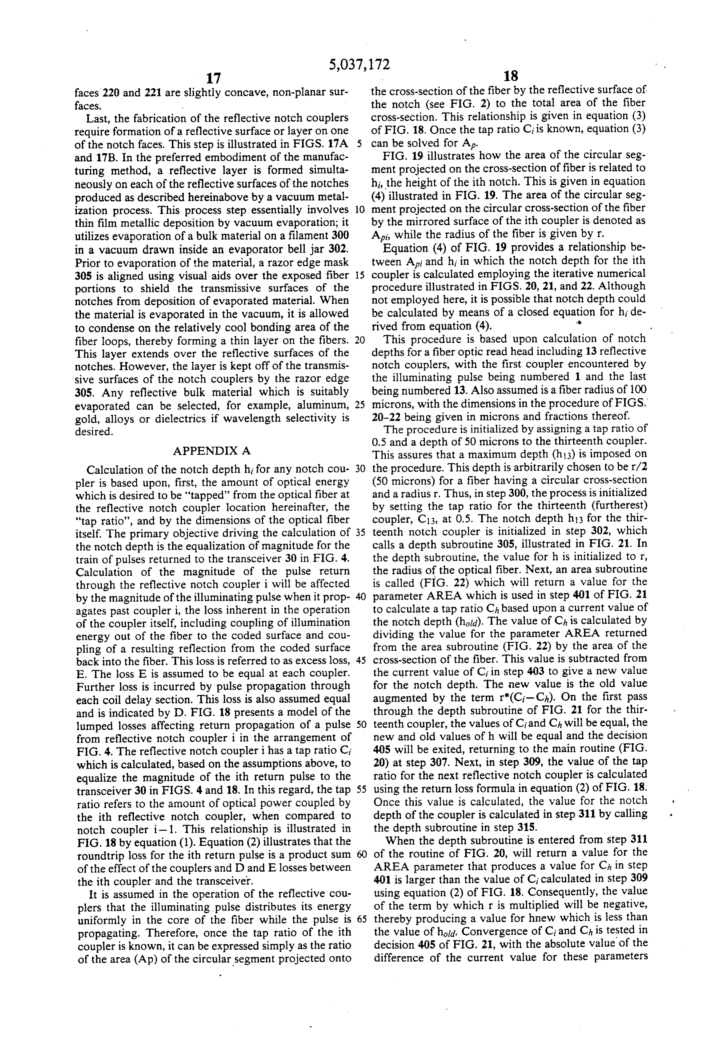
faces 220 and 221 are slightly concave, non-planar sur the cross-section of the fiber by the reflective surface of faces. the notch (see FIG. 2) to the total area of the fiber Last, the fabrication of the reflective notch couplers cross-section. This relationship is given in equation (3) require formation of a reflective surface or layer on one of FIG. 18. Once the tap ratio Ci is known, equation (3) of the notch faces. This step is illustrated in FIGS. 17A can be solved for A.
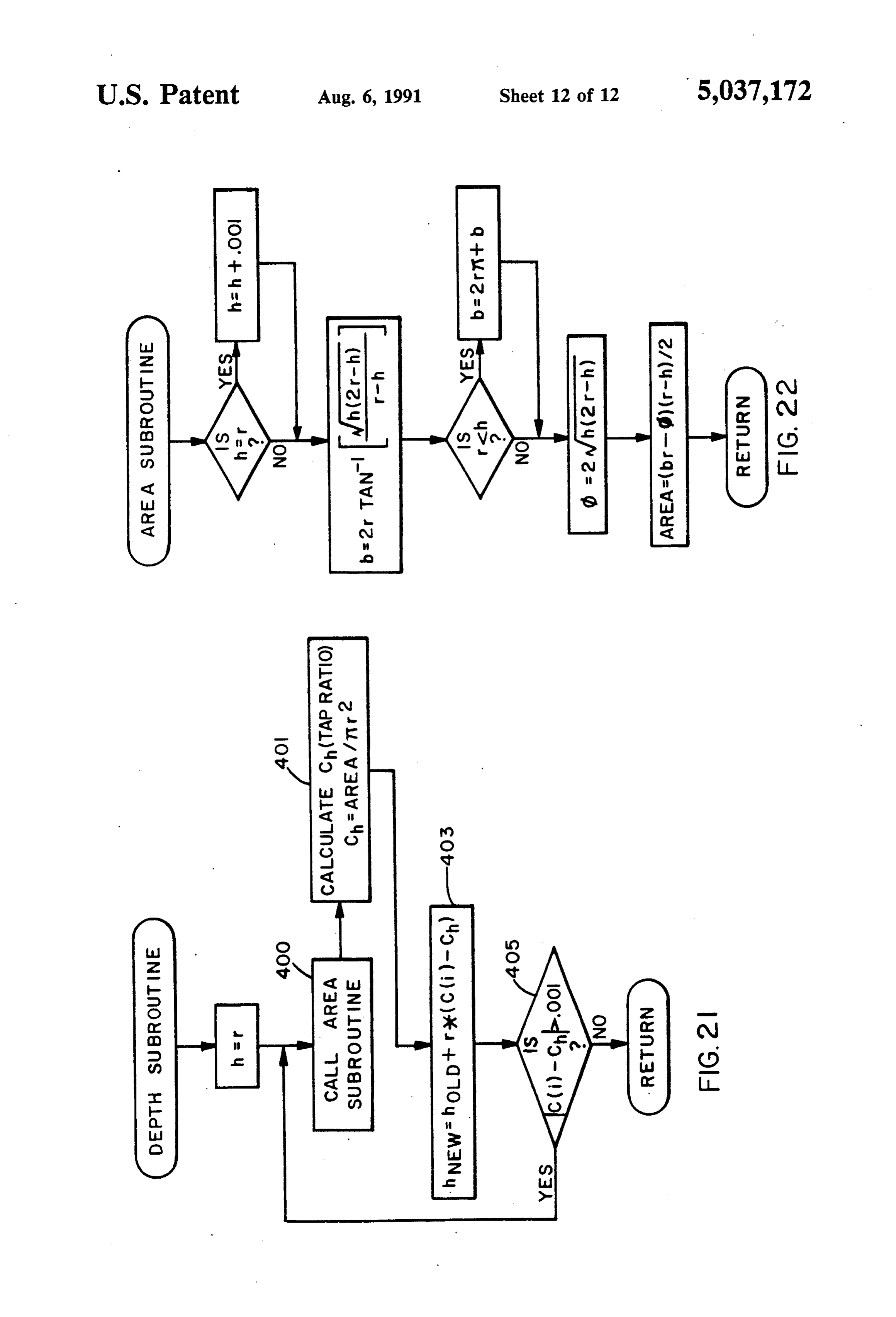
and 17B. In the preferred embodiment of the manufac FIG. 19 illustrates how the area of the circular seg turing method, a reflective layer is formed simulta ment projected on the cross-section of fiber is related to neously on each of the reflective surfaces of the notches hi, the height of the ith notch. This is given in equation produced as described hereinabove by a vacuum metal (4) illustrated in FIG. 19. The area of the circular seg ization process. This process step essentially involves O ment projected on the circular cross-section of the fiber thin film metallic deposition by vacuum evaporation; it by the mirrored surface of the ith coupler is denoted as utilizes evaporation of a bulk material on a filament 300 Api, while the radius of the fiber is given by r. in a vacuum drawn inside an evaporator bell jar 302. Equation (4) of FIG. 19 provides a relationship be Prior to evaporation of the material, a razor edge mask tween Api and h; in which the notch depth for the ith 305 is aligned using visual aids over the exposed fiber 15 coupler is calculated employing the iterative numerical portions to shield the transmissive surfaces of the procedure illustrated in FIGS. 20, 21, and 22. Although notches from deposition of evaporated material. When not employed here, it is possible that notch depth could the material is evaporated in the vacuum, it is allowed be calculated by means of a closed equation for hide to condense on the relatively cool bonding area of the rived from equation (4). : fiber loops, thereby forming a thin layer on the fibers. 20 This procedure is based upon calculation of notch This layer extends over the reflective surfaces of the depths for a fiber optic read head including 13 reflective notches. However, the layer is kept off of the transmis notch couplers, with the first coupler encountered by sive surfaces of the notch couplers by the razor edge the illuminating pulse being numbered 1 and the last 305. Any reflective bulk material which is suitably being numbered 13. Also assumed is a fiber radius of 100 evaporated can be selected, for example, aluminum, 25 microns, with the dimensions in the procedure of FIGS. gold, alloys or dielectrics if wavelength selectivity is 20-22 being given in microns and fractions thereof. desired. The procedure is initialized by assigning a tap ratio of
APPENDIX A
0.5 and a depth of 50 microns to the thirteenth coupler.
This assures that a maximum depth (his) is imposed on
Calculation of the notch depth hi for any notch cou 30 the procedure. This depth is arbitrarily chosen to be r/2 pler is based upon, first, the amount of optical energy (50 microns) for a fiber having a circular cross-section which is desired to be "tapped' from the optical fiber at and a radius r. Thus, in step 300, the process is initialized the reflective notch coupler location hereinafter, the by setting the tap ratio for the thirteenth (furtherest) "tap ratio", and by the dimensions of the optical fiber coupler, C13, at 0.5. The notch depth his for the thir itself. The primary objective driving the calculation of 35 teenth notch coupler is initialized in step 302, which the notch depth is the equalization of magnitude for the calls a depth subroutine 305, illustrated in FIG. 21. In train of pulses returned to the transceiver 30 in FIG. 4. the depth subroutine, the value for his initialized to r, Calculation of the magnitude of the pulse return the radius of the optical fiber. Next, an area subroutine through the reflective notch coupler i will be affected is called (FIG. 22) which will return a value for the by the magnitude of the illuminating pulse when it prop parameter AREA which is used in step 401 of FIG. 21 agates past coupler i, the loss inherent in the operation to calculate a tap ratio Ch based upon a current value of of the coupler itself, including coupling of illumination the notch depth (hold). The value of Ch is calculated by energy out of the fiber to the coded surface and cou dividing the value for the parameter AREA returned pling of a resulting reflection from the coded surface from the area subroutine (FIG. 22) by the area of the back into the fiber. This loss is referred to as excess loss, 45 cross-section of the fiber. This value is subtracted from E. The loss E is assumed to be equal at each coupler. the current value of Ci in step 403 to give a new value Further loss is incurred by pulse propagation through for the notch depth. The new value is the old value each coil delay section. This loss is also assumed equal augmented by the term r"(Ci-C). On the first pass and is indicated by D. FIG. 18 presents a model of the through the depth subroutine of FIG. 21 for the thir lumped losses affecting return propagation of a pulse 50 teenth coupler, the values of Ci and Ch will be equal, the from reflective notch coupler i in the arrangement of new and old values of h will be equal and the decision FIG. 4. The reflective notch coupler i has a tap ratio Ci 405 will be exited, returning to the main routine (FIG. which is calculated, based on the assumptions above, to 20) at step 307. Next, in step 309, the value of the tap equalize the magnitude of the ith return pulse to the ratio for the next reflective notch coupler is calculated transceiver 30 in FIGS. 4 and 18. In this regard, the tap 55 using the return loss formula in equation (2) of FIG. 18. ratio refers to the amount of optical power coupled by Once this value is calculated, the value for the notch the ith reflective notch coupler, when compared to depth of the coupler is calculated in step 311 by calling notch coupler i-1. This relationship is illustrated in the depth subroutine in step 315.
FIG. 18 by equation (1). Equation (2) illustrates that the When the depth subroutine is entered from step 311 roundtrip loss for the ith return pulse is a product sum 60 of the routine of FIG. 20, will return a value for the of the effect of the couplers and D and E losses between AREA parameter that produces a value for Ch in step the ith coupler and the transceiver. 401 is larger than the value of C calculated in step 309 It is assumed in the operation of the reflective cou using equation (2) of FIG. 18. Consequently, the value plers that the illuminating pulse distributes its energy of the term by which r is multiplied will be negative, uniformly in the core of the fiber while the pulse is 65 thereby producing a value for hnew which is less than propagating. Therefore, once the tap ratio of the ith the value of hold. Convergence of Ci and Ch is tested in coupler is known, it can be expressed simply as the ratio decision 405 of FIG. 21, with the absolute value of the of the area (Ap) of the circular segment projected onto difference of the current value for these parameters
Page 23
being tested against 0.001. For so long as the test is indentation extending from said cladding into beyond this test limit, the depth routine loops back to said core.
step 400 and proceeds as described above. 5. The optical transmission mechanism of claim 4 Inspection of FIG. 22 will reveal that, as the value of wherein each of said optical delay means is a respective h grows smaller, the value of the parameter AREA will 5 loop of said fiber.
diminish until the test of decision 405 in FIG. 21 is 6. The optical transmission mechanism of claim 4 passed. When the negative exit is taken from decision wherein said each of said couplers has a unique value 405, the index value i is decremented in step 313 of FIG. for a parameter, h, which is the depth of the indentation 20, the current values of C and h are stored in the file forming said each of said couplers.
to be provided for control of the CNC mill, and new O 7. A fiber optic coupler comprising:
values of Ci and hi are calculated again in steps 309 and a substantially cylindrical optical fiber for conducting 311. When i is hidecremented to zero, the negative exit light;
is taken from 315 and the procedure of FIG.20 is exited. a notch in the optical fiber with a first and second While we have described several preferred embodi 5 surface which meet within the fiber; and ments of our invention, it should be understood that a reflective means on the first surface for reflectively modifications and adapations thereof will occur to per transferring from the fiber light which is transmit sons skilled in the art. Therefore, the protection af ted through the second surface. forded our invention should only be limited in accor 8. The fiber optic coupler of claim 7, wherein the dance with the scope of the following claims. fiber has a core with a central axis, the reflective means We claim: reflectively transferring said light without said light 1. A fiber optic coupler, comprising: crossing the central axis.
an optical fiber for conducting an optical signal, said 9. A fiber optic read head for reading optical signals optical fiber including a substantially cylindrical from an optically-encoded surface, said optically en elongate core with a central axis and a cladding on 25 coded surface including a plurality of substantially par the outside of said core; allel coding tracks in which an optical code is repre an optically reflective first surface in said fiber, said sented by optically reflective surface portions in combi first surface extending from said cladding into said nation with optically non-reflective surface portions, core; said optical read head comprising:
said optically reflective first surface having a non 30 a carrier piece;
orthogonal first angle with respect to said central a plurality of alignment grooves in said carrier piece, axis; said alignment grooves disposed in an arrangement an optically transmissive second surface in said fiber, corresponding to said coding tracks; said second surface extending from said cladding a single optical fiber coiled into an elongate cylinder, into said core; and 35 said optical fiber including a core with a central said second surface meeting said first surface in said axis and a cladding on the outside of said core; core to form an indentation in said fiber, said inden a plurality of fiber loops extending from said elongate tation extending from said cladding into said core. cylinder, each of said fiber loops being attached to 2. The fiber optic coupler of claim 1, wherein said said carrier piece by being held in a respective one first angle is non-orthogonal with respect to said central of said alignment grooves; and axis. an optical coupler in each of said fiber loops at a 3. The fiber optic coupler of claim 2, wherein said location on said carrier piece adjacent the respec indentation is a V-shaped notch which extends into said tive groove in which said each of said fiber loops is core from said cladding no further than said central axis. held; each of said optical couplers including: 4. An optical transmission mechanism, comprising: 45 an optically reflective first surface in said optical an optical fiber for conducting an optical signal from fiber, said first surface extending from said clad an entry aperture, said optical fiber including a ding into said core;
core with a central axis and a cladding on the out said optically reflective first surface having a non side of said core; orthogonal first angle with respect to said central a plurality of optical delay means in series in said 50 axis;
optical fiber, each delay means for delaying the an optically transmissive second surface in said transmission of optical signals through said optical fiber, said second surface extending into said fiber; and cladding into said core; and a plurality of optical couplers in series in said optical said second surface meeting said first surface in said fiber, said optical delay means alternating with said 55 core to form an indentation in said fiber, said optical couplers in said optical fiber, each of said indentation extending from said cladding into optical couplers including: said core.
an optically reflective first surface in said optical 10. The fiber optic read head of claim 9 wherein a fiber, said first surface extending from said clad parameter h is an indentation depth taken radially in ding into said core; said fiber from said cladding toward said central axis said optically reflective first surface having a non and hi, the value of h for the indentation in the ith loop, orthogonal first angle with respect to said central is less than, or equal to, the radius of said fiber. axis; 11. The fiber optic read head of claim 10 wherein his an optically transmissive second surface in said less than hi-li, the value of h for the indentation in a loop fiber, said second surface extending from said 65 adjacent said ith loop.
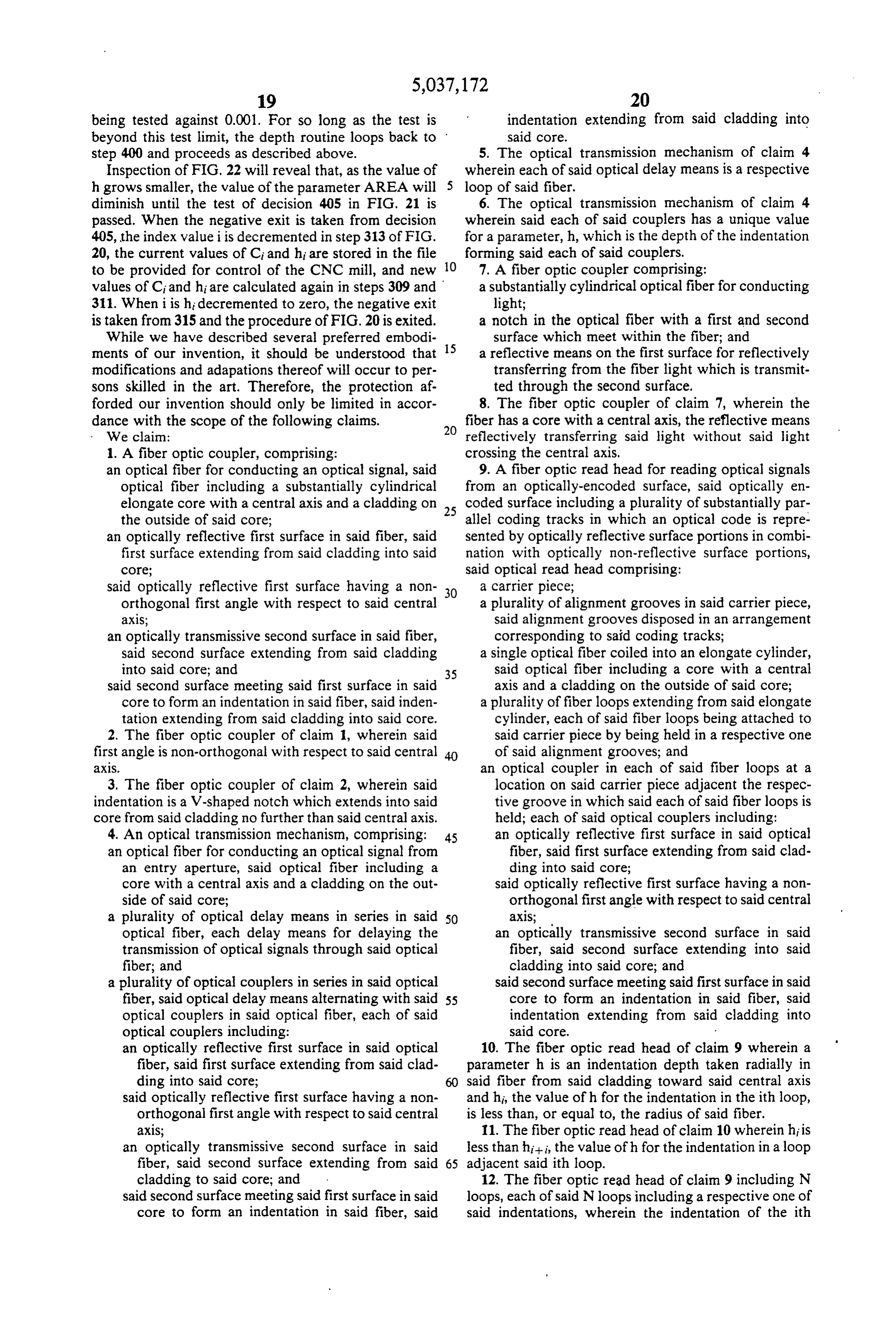
cladding to said core; and 12. The fiber optic read head of claim 9 including N said second surface meeting said first surface in said loops, each of said N loops including a respective one of core to form an indentation in said fiber, said said indentations, wherein the indentation of the ith
Page 24
loop couples a portion Cioflight travelling in said fiber, such that:
such that: pi={4(2hir-h2)},
and
Ci <Ci-, and wherein: forming an optically reflective sheet on the first sur face of each notch.
16. A method of manufacturing a plurality of optical bi=2rarctan(2rhi-h2)/(r-h)), couplers in an optical fiber, said optical fiber including where hi is the depth of the indentation of the ith 10 a cylindrical core with a central axis and a cladding on loop and r is the radius of said fiber, the outside of the core, the method employing a cutting 13. The fiber optic read head of claim 12 wherein wheel and comprising the steps of: (1) arranging a plurality of fiber sections of the fiber
C2 Ci+1. in parallel on a work surface; 15 (2) positioning the cutting wheel at a distance from 14. A method of manufacturing an optical coupler in the work surface such that the edge of the cutting an optical fiber which includes a core with a central axis wheel is located below the cladding and above the and a cladding applied to said core, said method com central axis of a first fiber section; prising the steps of: (3) cutting the first fiber section tangentially with the cutting said fiber tangentially to form a notch in said 20 edge of the cutting wheel to form an indentation in fiber, said notch extending through the cladding the first fiber section, the indentation including a into the core of said optical fiber, said notch includ first and second surface which meet in the core ing a first and a second surface, said first surface above the central axis;
having a non-orthogonal angle with respect to said (4) adjusting the distance between the cutting wheel central axis; and 25 and the work surface such that the edge of the attaching an optically reflective material to substan cutting wheel is located below the cladding and tially all of said first surface. above the central axis of a second fiber section; and 15. A method of manufacturing a plurality of optical (5) cutting the second fiber section tangentially with couplers in an optical fiber, said optical fiber including the edge of the cutting wheel to form an indenta a core with a radius r and a central axis, and a cladding 30 tion in the second fiber section including a first and applied to said core, said method comprising the steps second surface which meet in the core above the of: central axis.
17. The method of claim 16 wherein the second fiber coiling said optical fiber; section is adjacent the first fiber section. while coiling said fiber, extending N elongate, sub 35 18. The method of claim 16 wherein the step of posi stantially parallel sections of said optical fiber;
in each of said N parallel sections, cutting said fiber to tioning positions the edge of the cutting wheel at a position which is a first distance above the central axis form a notch for output coupling a portion C of and light traveling in said fiber, the notch in each sec ting the step of adjusting positions the edge of the cut wheel at a position which is a second distance tion extending through the cladding and into the above the central axis, the first and second distances core of said optical fiber and including a first sur face and a second surface, said first surface having being
unequal.
The method of claim 16 wherein the sequence of a non-orthogonal angle with respect to said central steps (4) and (5) is performed for each of the remaining aXIS; fiber sections.
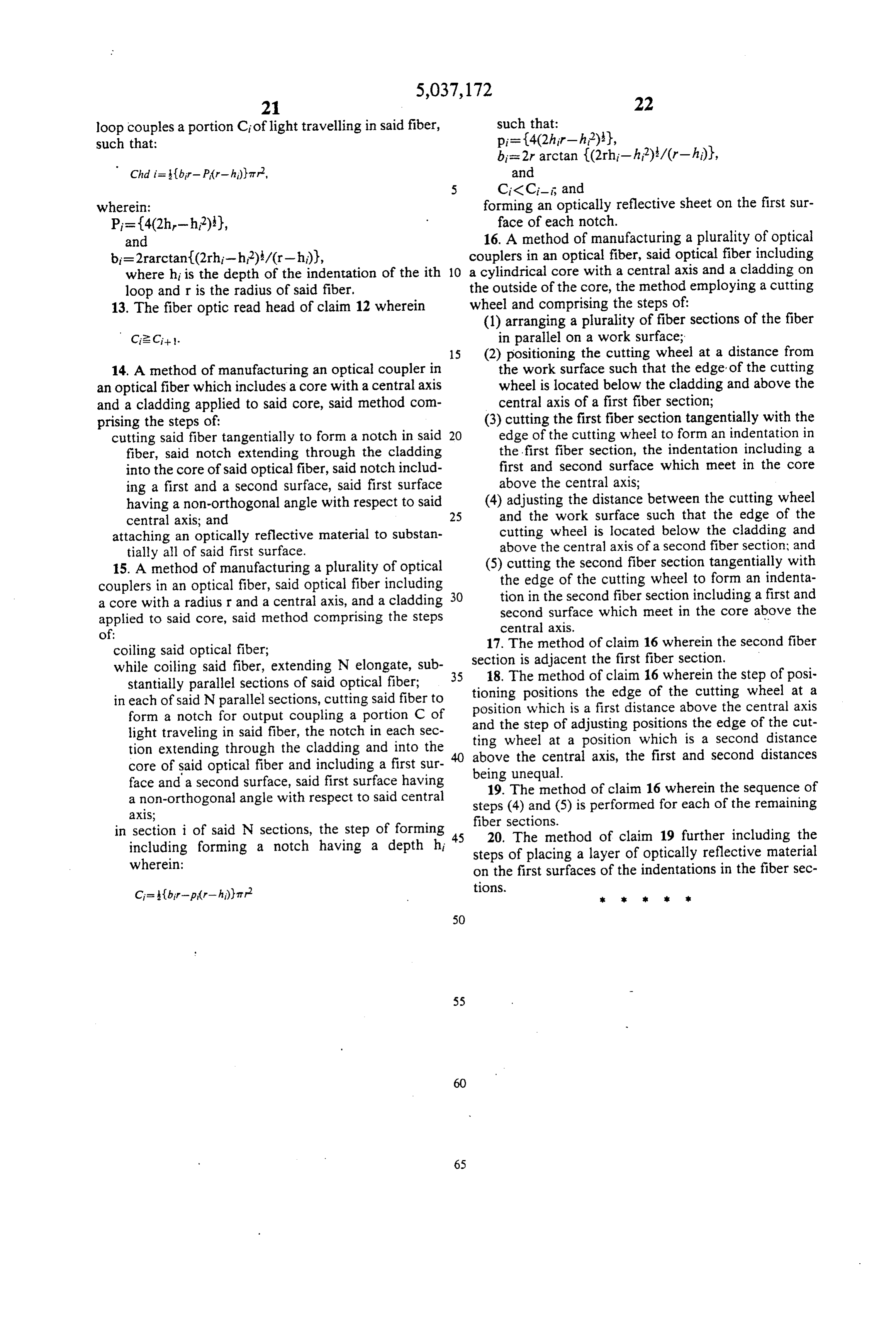
in section i of said N sections, the step of forming 45 20. The method of claim 19 further including the including forming a notch having a depth hi steps of placing a layer of optically reflective material wherein: on the first surfaces of the indentations in the fiber sec tions.
Provenance
- Collection
- Cited prior art
- Original PDF
- patentimages.storage.googleapis.com →
- Filed
- 1990-12-11
- Pages
- 24
- Method
- pdftotext (the PDF's own text layer) + pdftoppm 300dpi page scans
- Source
- Google Patents bibliographic record
- Granted
- 1991-08-06
- Inventors
- Edwin D. Hekman; Thomas J. Lund; John L. Maida; Deepak Varshneya; Teledyne Industries Inc
- Transcribed from
- patentimages.storage.googleapis.com →