patent · US4268116
Method and apparatus for radiant energy modulation in optical fibers
19 May 1981
Page 1 — bibliographic record
United States Patent 19 11 4,268,116 Schmadel et al. 45) May 19, 1981
54 METHOD AND APPARATUS FOR RADANT OTHER PUBLICATIONS
ENERGY MODULATION IN OPTICAL
FIBERS PCT/US78/001.98, to P. Macedo et al., Jun. 1979. F. Gfelle et al., “Modulator & Tap for Optical Fiber (75) Inventors: Donald Schmadel; William H. Culver; Systems,” in IBM Tech. Disc. Bull, vol. 21, No. 5, Oct.
Md. Kawasaki et al., "Narrow-Band Bragg Reflectors in Optical Fibers,' in Optics Letts, vol. 3, No. 2, Aug.
73) Assignee: Optelecom Incorporated, 1978, pp. 66–68.
Gaithersburg, Md. J. A. Bucaro et al., "Measurement of Sensitivity of Optical Fibers for Acoustic Detection," in Applied Op 21 Appl. No.: 88,579 tics, vol. 18, No. 6, Mar. 1979. P. G. Cielo, “Fiber Optic Hydrophone:Improved Strain 22 Filed: Oct. 26, 1979 Configuration & Environmental Noise Protection,' in
51 Int. Cl. .......................... G02B 5/14; G02F 1/11; A. Warner et al., "Miniature Acoustooptic Modulators for Infrared Optical Communications," IEEE Jour.
52 U.S. C. .............................. 350/96.29; 350/96.19; Quantum Electronics, vol. QE-O Jun. 73. 350/373; 350/358; 350/359 Jeunhomme et al., “Directional Coupler for Multimode (58 Field of Search ............... 350/96.19, 96.29, 96.13, Optical Fibers," Applied Physics Letts, vol. 29, No. 8,
H. Hsu et al., "Single Mode Optical Fiber Pickoff Cou 56) References Cited pler," Applied Optics, vol. 15, No. 10, Oct. 1976.
3,625,589 12/1971 Snitzer ............................. 350/96.29 Attorney, Agent, or Firm-Kerkam, Stowell, Kondracki 3,645,603 2/1972 Smith ............................... 350/96.29 & Clarke 3,819,250 6/1974 Kibler ............................... 350/96.29 57 ABSTRACT 3,931,518 1/1976 Miller ............................... 350/96.15 4,006,963 2/1977 Baues et al. ...................... 350/96.14 Radiant energy is caused to modulate in phase and fre 4,039,249 8/1977 Kaminow et al. ............... 350/96.14 quency in a single mode optical fiber by means of a 4,068,191 1/1978 Zemon et al. .. ... 350/96.29 relatively movable, spatially periodic perturbation. 4,086,484 4/1978 Steensma .... ... 350/96.29 4,118,676 10/1978 Redman ........................... 350/96.30 31 Claims, 24 Drawing Figures 4,128,299 12/1978 Maher ............................. 350/96.13
Page 2
Drawing sheet — no readable text.
Page 3
Drawing sheet — no readable text.
Page 4
Drawing sheet — no readable text.
Page 5
Drawing sheet — no readable text.
Page 6
Drawing sheet — no readable text.
Page 7
The invention provides frequency multiplexing many
METHOD AND APPARATUS FOR RADEANT signals into the same fiber using multi-wavelength radi ENERGY MODULATION IN OPTICAL FIBERS ant energy in the fiber and adjusting the spatial period of each spatially periodic perturbation to interact only
DESCRIPTION with a particular different wavelength of the multi Technical Field wavelength energy.
The invention provides for time division multiplexing
The invention relates to the field of radiant energy many signals into the same single mode fiber by using modulation in single mode optical fibers. pulsed, for example, light in the fiber and locating vari 10 ous spatially periodic perturbations at known distances
Background of Prior Art
The prior art for either phase modulation or fre along the fiber. Though various spatially periodic per quency modulation of, for example, light in an optical reflection ofmay turbations interact with the same wavelength, the fiber utilized the acousto-optic effect wherein the signal source at differentpulsed the radiant energy will arrive at the to be imposed onto the light carried in the fiber is used periodic perturbation canThe
signals from each spatially sorted accordingly.
to mechanically or acoustically excite the fiber. This
The invention provides mechanical or acoustical excitation gives rise to a varia optical demodulation system entirely for the construction of an tion in the optical index of the core of the fiber. The mode fiber by the placement of a second within the single result is a variation in the optical path length for the along the fiber. The optical demodulationoptical system grating oper light traveling in the fiber. This light is therefore modu 20 lated in phase and frequency by the signal. For glass ates somewhat as a Fabry Perot interferometer and fibers the change in optical index is quite small for a allows the first stage of optical frequency or phase de given energy of mechanical or acoustical excitation. In modulation to occur as near the signal input as is de order to obtain sufficient modulation, this necessitates sired, thus minimizing thermal and mechanical noise either high signal energy or long interaction lengths 25 and eliminating the need for a separate and costly inter where the interaction length is the length of fiber which ferometric system.
must be acoustically excited wherein modulation oc The invention includes a detection system which curs. The sensitivity of optical fibers to direct acoustical spectrally locates the reflection peaks of the spatially modulation is discussed by J. A. Bucaro in Applied Op periodic perturbations.
tics, Vol. 18 No. 6; Mar. 15, 1979. A device specifically 30 The invention also includes a detection system to be utilizing this effect was built by Arthur W. Warner and used with the optical demodulation system above, the Douglas A. Pinnow, and is reported in abstract in the output of which is the spectral location of the optical IEEE Journal of Quantum Electronics, Vol. QE-O; pp. resonances of the interferometer thus minimizing the 659-660; June, 1973. effect of amplitude variations of the, for example, light The invention uses a novel type of movable, spatially 35 SOCC.
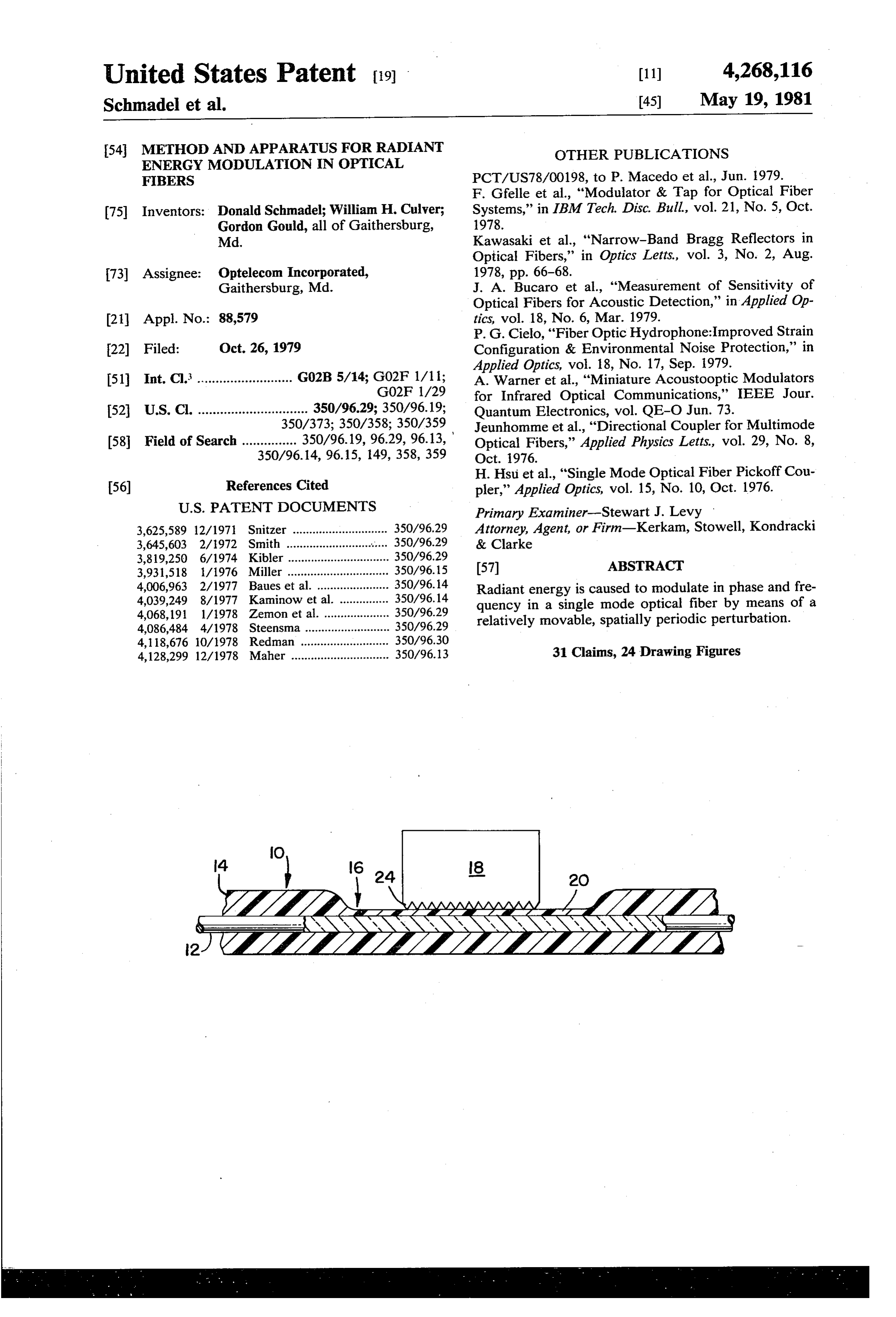
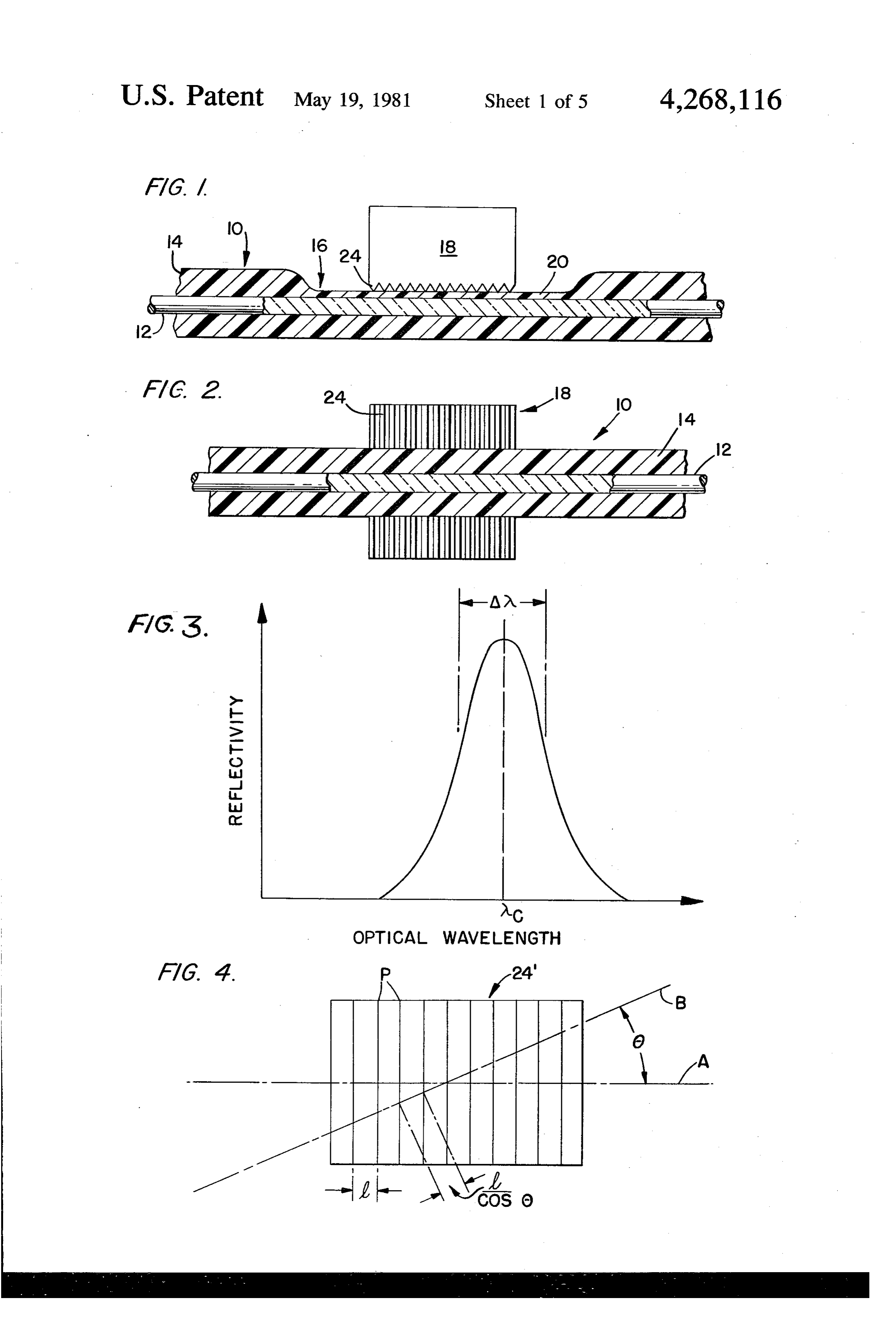
periodic perturbation in the wall of a single mode opti The invention may be defined as including: cal fiber waveguide to achieve modulation. The effect means for modulating radiant energy in a single mode of a stationary spatially periodic perturbation in a rect clad optical fiber comprising a clad single mode angular waveguide is discussed by Dietrich Marcuse in optical fiber having a modulation control zone Bell System Technical Journal; Vol. 48, pp. 3233-3242; where the cladding is partially removed or formed December, 1969. The effect of another type of station with a decreased thickness relative to the remain ary, spatially periodic perturbation is discussed by B. S. der of the cladding; an optical grating; means Kawasiki et al in Optic Letters, Vol. 3, No. 2; August, mounting the optical grating in the control zone 1978. with the crests of the optical grating positioned In each case, the spatially periodic perturbations 45 generally normal to the optical fiber, and means for were forced to be stationary by the manner in which longitudinally displacing the optical grating rela they were achieved. tive to the optical fiber to cause a narrow band of BRIEF SUMMARY OF INVENTION the radiant energy in the optical fiber to be modu The invention causes modulation in a signal mode 50 The lated in phase and/or frequency. optical fiber by means of a movable, spatially periodic radiantinvention also includes a method of modulating perturbation. The spatially periodic perturbation is used mode optical fiberphase energy in and/or frequency in a single to reflect a narrow band of radiant energy wavelength the cladding from a single moderemoving comprising optical a portion of fiber having a which by virtue of the motion of the spatially periodic cladding about the fiber, mounting an optical grating on perturbation is modulated in phase and/or frequency. 55 said fiber in the zone where the portion of the cladding The invention causes the spatially periodic perturbation has been removed with the crests of the grating oriented by means of an optical grating placed near the core of a generally single mode fiber. The spatially periodic perturbation is fiber, and normal to the longitudinal axis of the optical causing relative longitudinal displacement of moved by moving the optical grating with respect to the fiber. 60 the grating relative to the longitudinal axis of the fiber. The invention provides many means of coupling the BRIEF DESCRIPTION OF DRAWINGS motion of the optical grating of the fiber to various types of signals or conditions. These means include FIG. 1 is an enlarged partially sectional view in ele coupling to both high and low frequency signals includ vation of a single mode fiber in association with an ing static signals or conditions. These means allow cou 65 optical grating constructed in accordance with the pling for electrical, electro-magnetic, magnetic and teachings of the present invention.
acoustical signals and for thermal levels and chemical FIG. 2 is a bottom planned view of the structures conditions and humidity. illustrated in FIG. 1;
Page 8
FIG. 3 is a graphic illustration illustrating the inten core, the clad may be partially removed by grinding or sity of reflected light vs wavelength for a spatially peri otherwise.
odic perturbation; In FIGS. 1 and 2, 10 generally designates a single mode optical fiber having a light transmitting core 12
FIG. 4 illustrates a grating surface greatly magnified;
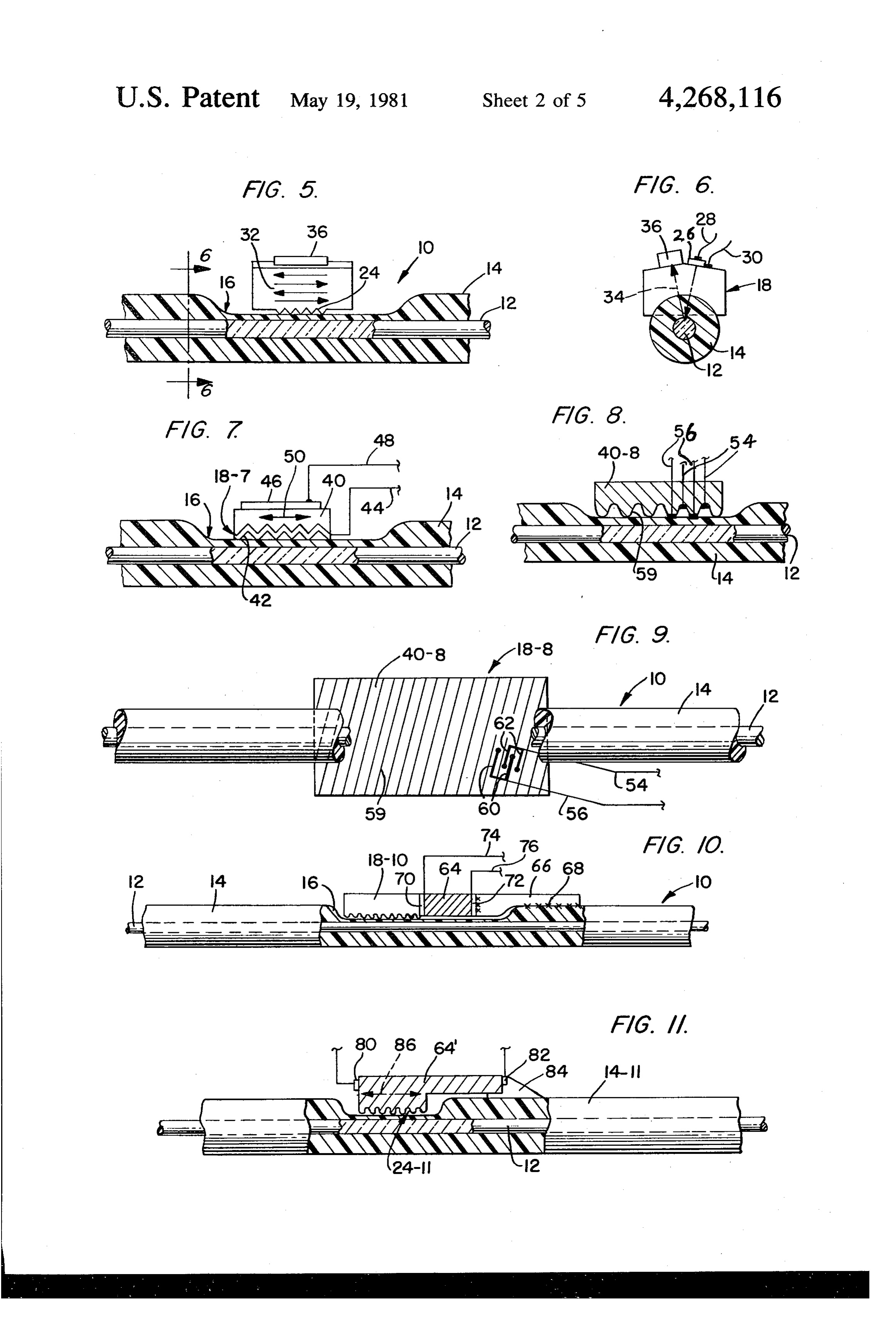
FIG. 5 is a view like FIG. of another form of the 5 of, for example, plastic, glass or quartz, and a lower present invention; index of refraction cladding 14, of glass or plastic. The FIG. 6 is an end view of the structures shown in FIG. cladding 4 is illustrated as being partially removed by, 5; for example, grinding as at 6. In the ground zone 16 is FIG. 7 is a view like FIG. 5 of another form of the mounted at optical grating generally designated 18. The present invention; O optical grating 18 consists of periodic alternation of FIG. 8 is a view like FIG. of still another form of teeth and grooves 24.
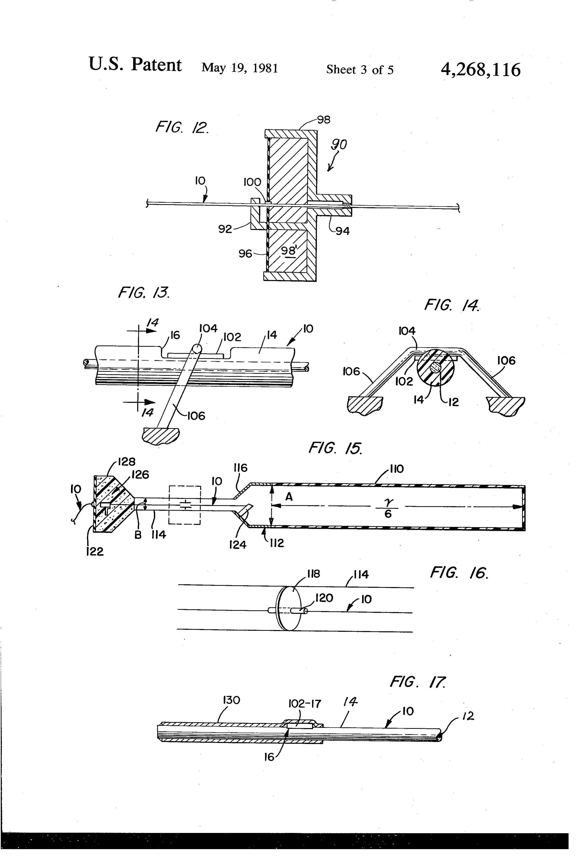
the present invention; In such a system, the wall 20, in the ground zone 16 FIG. 9 is a bottom plan view of the structures shown surrounding the core 12 of the single mode fiber near in FIG. 8: the optical grating 58 consists of a thin layer of glass, or FIG. 10 is a view like FIG. 1 of still another form of 15 plastic 20 and a periodic alternation of teeth and the present invention; grooves 24 to thus provide a spatially periodic perturba FIG. 11 is a view like FIG. 1 of another form of the tion of the optical index of the wall surrounding the present invention; core of the fiber. The evanescent field of the light trav FIG. 12 is a diagrammatic sectional view of the pres eling in the fiber will be reflected back to the source by ent invention coupled to a microphone; 0 this spatially periodic perturbation when the period is FIG. 13 illustrates a system for holding a thin film near an integral multiple of W. Such a phenomenon, grating from radial displacement; called Bragg reflection, is illustrated graphically in FIG. 14 is an end view of the structures illustrated in FIG. 3.
FIG. 13; The graph, FIG. 3, shows the intensity of reflected FIG. 15 illustrates the system of the present invention light vs wavelength for a particular spatially periodic coupled to a hydrophone; perturbation. The center Ac of the wavelength band FIG. 16 is an enlarged view of a portion of the struc reflected is:
tures illustrated in FIG. 15; Ac=(ND/2)
FIG. 17 illustrates the application of the present in- 30 vention wherein the spatially periodic perturbations are where moved by thermal expansion or contraction; D is the length of the spatial period; FIG. 18 illustrates the application of the present in N is effective optical index for the single mode fiber. vention wherein the grating is moved by a coil; The width of this band of wavelengths is given by: FIG. 19 is like FIG. 18 wherein the coil is the immov- 35 able element of a solenoid;
FIG. 20 illustrates a form of the invention wherein the grating is angularly displaced; where
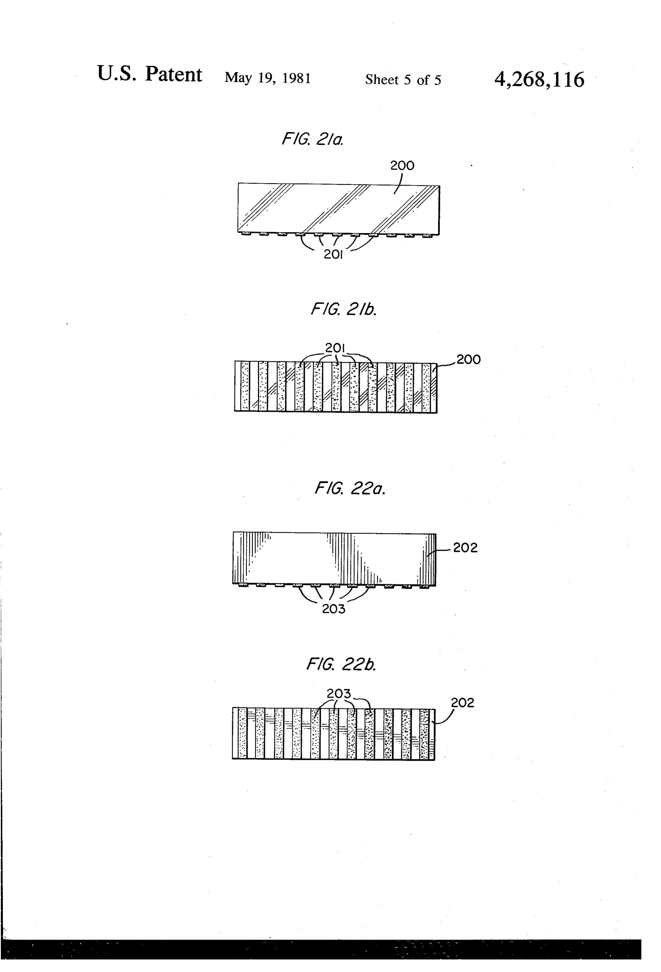
FIG. 21a is a side elevational view of another form of =length of fiber in contact with the grating. the present invention; 40 The reflectivity of the spatially periodic perturbation FIG. 21b is a diagrammatic bottom plan view of the within this band of wavelengths may be increased or structures shown in FIG. 21a. decreased by a common factor by placing the grating FIG. 22a is a view like FIG. 21a of still another form nearer or further from the core and by using grating of a modulation device of the present invention; and materials of higher or lower optical indices of refrac FIG. 22b is a diagrammatic bottom plan view of the 45 tion. Further, because the spatially periodic perturba structures shown in FIG. 22a. tion is caused by a periodic perturbation in the optical DETAILED DESCRIPTION OF INVENTION index of the wall of a single mode fiber, the grating may be any material having a surface with a periodic varia
The invention will now be described in detail tion in its optical index. Holographic film grating is such wherein the single mode optical fiber is employed as a 50 a material.
light pipe. However, it will be understood that other The invention allows also for a spatially periodic electromagnetic radiant energy rays could be employed perturbation of conductivity. In such a case the inven with the single mode fiber such as infrared. tion places near the fiber core a surface of periodically A single mode optical fiber is a fiber constructed so as varying conductivity as in FIGS. 21a and 21b. The slab to allow only the lowest order mode to propagate. This 55 marked 200 is a nonconducting material such as glass or lowest order mode for some single mode fiber construc plastic, upon which are evaporated conductive strips tions is two fold degenerate. In these cases the lowest 201, which could be, for example, metal. The slab is order mode contains two states of propagation which oriented near the fiber core so the metal strips are gen are distinguished by the fact that their polarizations are erally perpendicular to the fiber optic axis. Another mutually perpendicular. 60 means for establishing the spatially periodic perturba As hereinbefore disclosed, the invention causes a tion of conductivity is to use a slab of material, 202, in movable spatially periodic perturbation in the wall of a FIGS. 22a and 22b, which is conductive and upon single mode optical fiber by using an optical grating. which are evaporated strips, 203, of nonconductive The optical grating is placed near enough to the core of material, e.g., S.O. Such slabs as in FIGS. 2a and 21b, the fiber to interact with the evanescent or non-radia- 65 will be called "optical gratings” or “gratings'. The tion fields of the light which is traveling in the fiber. In invention provides the following means for obtaining a cases where the single mode optical fiber has a cladding particular spatial period from a grating having a shorter too thick to permit placement of the grating near the spatial period.
Page 9
FIG. 4 illustrates a grating surface 24' greatly magni It is further understood that the grating may be an fied. The lines marked 'P' are lines of constant refrac integral part of the transducer, that is, the grating itself tive index, or conductivity, along the grating surface. may be constructed from a piezoelectric material as, for The spatial variation is perpendicular to these lines example, in FIGS. 7, 8 and 9.
which are spaced each one period apart. Various single In FIG. 7, the piezoelectric block 40 is provided with mode fiber orientations relative to the surface 24' are grating 18-7 on its lower surface, which grating is met depicted by means of a dashed line representing the allized as at 42 to provide one of the electrodes and is single mode fiber optical axis. For orientation A, repre provided with an electrical lead 44. The other electrode sented by the dashed line marked "A" perpendicular to 46 on the top surface of the piezoelectric crystal 40 is lines P, the spatial period is as seen from the drawing 10 connected to lead 48. Arrow 50 depicts the direction of equal to 1. The spatial period for the orientation marked motion of the grating 18-7 in respect to the axis of the "B" is l/cosé which is greater than l, the "normal spatial core fiber 12 of the single mode optical fiber 10. period of the grating, where 6 is the angle between the In FIGS. 8 and 9, the grating 18-8 of the piezoelectric optical axis of the single mode fiber in orientation A, transducer chip 40-8 illustrates a form of the invention which is perpendicular to the lines of equal optical 15 where the teeth and grooves or crests and troughs of index of the surface, and orientation B. the grating are formed by a surface acoustic wave indi A spatially periodic perturbation so constructed can cated by lines 59. In such a case, a change in frequency be moved relative to the fiber simply by moving the of the input signal via conductors 54-56 to the network grating relative to the fiber. The invention couples the of electrodes 60-62 causes a change in the separation of motion or position of the grating as measured along the 20 the crests and troughs of the grating formed by the optic axis of the single mode fiber to an input signal or surface acoustical wave. The electrodes 60-62 can be parameter. The result is reflection of a particular wave formed by metallizing portions of the lower surface of length band of the light which is traveling in the fiber the transducer chip 40-8. The wavelength band, that by a spatially periodic perturbation which is moving or such a grating would reflect, would shift in wavelength positioned in response to an input signal or parameter. 25 in direct response to the change in frequency of the The moving spatially periodic perturbation will mod input signal. The input frequency to the electrodes ulate the frequency of the reflected light consistent with 60-62 can be coupled to an input signal or parameter the relativistic Doppler shift as specified in the subject thus modulating the frequency of the reflected wave matter of the physical principle of Special Relativity. length band center (FIG. 3). In such cases the term In cases such that the position of the grating as mea 30 single mode optical fiber will also include multimode sured along the optical axis of the single mode fiber is optical fibers which only allow modes to propagate coupled to an input parameter, then reflection of the with propagation constants nearly equal so as to main wavelength band will occur at various locations along tain optical coherence over the length of the grating. the single mode fiber as a function of this input parame The invention detects the input signal frequency by ter. These changes in location of the spatially periodic 35 tracking the spectral location of the reflected wave perturbation as caused by the changes in location of the length band using an optical spectrometer. In cases grating cause changes in the optical path length for light wherein one may control the frequency of the input traveling in the single mode fiber to the spatially peri signal, such a device as depicted in FIG.9 may be used odic perturbation, being reflected, and traveling back to as a tunable filter to select various wavelength bands of the source. The change in optical path length modulates 40 light.
the phase of the reflected light relative to the phase of FIG. 10 depicts a second means as provided by the the source of the light. Calculations reveal that such a invention of coupling an electrical input signal to the system, i.e., moving the grating to achieve modulation motion or position of the grating. This means employs a requires much less signal energy than the previous state longitudinal-mode piezoelectric transducer 64 with one of the art of fiber modulation systems. 45 side bonded to the grating 18-10 and the opposite side The invention contains several means for coupling bonded stationary relative to the single mode fiber arm the motion or position of the grating to an input signal 66 cemented as at 68 to the cladding 14 of the single or parameter. FIGS. 5 and 6 illustrate a means which mode optical fiber 10. Opposite sides of the longitudi acoustically couples a shear wave transducer 26 to the nal-mode transducer 64 are metallized as at 70 and 72 to grating 18. An electric input signal via electrodes 28 and 50 which are attached electrical leads 74 and 76. For low 30 activates the shear-mode transducer 26, thus causing frequency electrical signals coupled to the transducer an acoustical shear wave in the plane containing the 64, the transducer will expand and contract in the direc teeth 24 of the grating 18. An acoustical shear wave is tion of the electric field. Since the side opposite the characterized by material motion shown by arrows 32 grating 18-10 is restrained relative to the single mode perpendicular to its direction of propagation shown by 55 fiber, the grating teeth and grooves will move with a arrows 34. The invention arranges the shear-mode component of the velocity vector parallel to the optical transducer 26 so as to polarize the material motion par axis of the single mode fiber in response to the input allel to the optic axis of the single mode fiber which is signal.
also parallel to the direction of spatial periodicity of the The invention includes the adaptation of the means spatially periodic perturbation. The spatially periodic 60 illustrated in FIG. 10 wherein the grating is an integral perturbation therefore moves parallel to the optic axis part of the transducer as, for example, that particular of the single mode fiber as caused by the motion of the case depicted in FIG. 11.
teeth of the grating which is in response to the electric In FIG. 11, 64 is a longitudinal mode piezoelectric input signal to the shear-mode transducer. An absorber transducer provided with end electrodes 80 and 82. The 36, consisting of a block of a material accoustically 65 lower face of the transducer 64 is provided with grat matched and attached to the top of the element carrying ing 24-11 and the end of the transducer adjacent elec the grating 18 reduces unwanted reflection of the shear trode 82 is cemented to the cladding 14-11 of the single wave propagation. mode optical fiber assembly 10 as at 84. Arrow 86 de
Page 10
picts the motion of the grating in response to an oscillat The funnel-like surface will impedance match the gas ing electrical input to the electrodes 80 and 82. filled rigid tube in the membrane to the ocean if: In all means wherein piezoelectric transducers are employed the invention provides for the substitution of the piezoelectric transducer with a magnetostrictive 5 transducer and a solenoid with a movable core when vhere the purpose is to move or position the grating. Further, Og = the specific acoustical impedance of the gas. the invention provides a means of coupling to magnetic OW = the specific acoustical impedance of the water. signals directly by substituting the piezoelectric trans and A and B are the diameters of the two tubes as ducer with a magnetostrictive material which will pro 10 shown in FIG. 15. Once the acoustical wave has en duce motion or effect the change of the position of the tered the small rigid tube it will strike the low mass grating when exposed directly to the magnetic signal or diaphragm or sail 118, for example, a colloidal film condition. The invention also provides for the direct which is bonded to a low mass grating 120, FIG. 16. sensing of electrical fields and electro-magnetic fields The grating will move in response to the acoustical with piezoelectric transducers. In such case, the piezo 15 signal.
electric material may be exposed directly to the field. The single mode fiber 10 is rigidly attached within The resulting motion or change of shape of the material tube 114 at end plate 122. Where the fiber passes will move or position the grating. The invention pro through an opening in the end plate 122. The other end vides for the addition of antenna electrodes to gather a of the fiber 10 is rigidly attached to an attachment block greater portion of energy available when sensing weak 124 secured in the impedance transformer section 116. fields. The electrodes then electrically conduct this Suitable acoustic absorption material 126 fills the end energy to the piezoelectric transducer. This results in an zone 128 of the device to reduce the reflection of acous antenna system which connects to the receiver or am tical waves from the end 122 of the hydrophone which plifier by means of an optical fiber thus eliminating could cause the sail 118 to move and in turn to oscillate electrical noise in the antenna to receiver link and the 25 the grating 120.
danger of lightning striking the antenna and being con A fourth means provided by the invention for cou ducted into the receiver or amplifier. pling the grating to input signals relates to thermal mea A third means of coupling the motion or position of surements. Such a means mechanically couples the posi the grating to a signal relates to signals which are acous tion of the grating to a material which may change in tical. In such cases, the invention couples the acoustical 30 shape or size under the influence of thermal changes. signal directly to the grating as, for example, that shown FIG. 17 illustrates a particular case wherein the tem in FIG. 12. In FIG. 12, 90 generally designates a micro perature sensitive material is in the form of a tube and is phone system including a single mode optical fiber 10 collapsed around the single mode fiber and grating. In cemented in front and rear portions 92 and 94 of a mi FIG. 17 the single mode optical fiber is designated 10, crophone 90. The fiber also passes through an opening 35 and a portion of the cladding 14 is in part removed in in the microphone diaphragm 96 secured to the wall 98 zone 16. In the zone 16 is mounted a thin film grid or of the microphone. A grating 100 is carried by the dia grating 102-17 such as the grating 102 illustrated in phragm 96 at a position such that the grating will oscil FIG. 13.
late upon movement of the diaphragm 96 sensing acous Shrunk about a longitudinal section of the fiber 10, tical waves, causing it to move with a velocity compo 40 including the zone 16, is a thermally expandable tube nent parallel to the single mode fiber axis. The dia 130 whereby thermal expansion and contraction of the phragm is mechanically connected to the grating thus length of the tube causes a narrow band of light to be causing motion of the grating in response to the acousti modulated within the fiber 10. In such cases, the grating cal signals. Between wall 98 and the diaphragm 96 is a will move an amount equal to the difference in the suitable absorber 98' such as foam plastic. In cases of 45 thermal expansions of the single mode fiber and the tube low energy acoustical signals, the invention provides material.
the use of low mass gratings and low mass grating sus The invention further provides a means employing pension means such as spider web or quartz fibers as the grating itself as the material used to change shape or depicted in FIGS. 13 and 14. size under the influence of thermal changes. In such a In FIGS. 13 and 14 there is illustrated a single mode 50 means, a change in the size of the grating will change optical fiber 10 having a portion of the cladding 14 the spatial period of the spatially periodic perturbation removed as at 16. In the depression formed at 16 is a by a proportional amount thus spectrally shifting the thin film grating 102. The thin film grating is held in reflected wavelength band of the spatially periodic close optical relation to the core 12 of the optical fiber perturbation. Detection for such a means amounts to 10 by a quartz fiber or web generally denoted 104. The 55 obtaining a spectral analysis of the light reflected by the extended ends 106 of the glass fiber 104 are secured to spatially periodic perturbation and measuring the stationary means as illustrated. change in wavelength AW of the center wavelength, A. In cases of detecting acoustic waves in water, the As from the previous equation for Ac, ANc is propor invention provides the hydroacoustic antenna shown in tional to AD, where AD is the change in spatial period FIG. 15 and in part in FIG. 16. 60 of the spatially periodic perturbation. Using a grating A cylindrical low impedance membrane 110, A/6 in material having a coefficient of thermal expansion much length, where A is the shortest acoustic wavelength of larger than that of the single mode fiber, then the ther interest, contains a gas, such as He or air, and acts as a mal conditions being monitored are found as a direct diaphragm coupling the oceans acoustic signal into the mathematical function of AA.
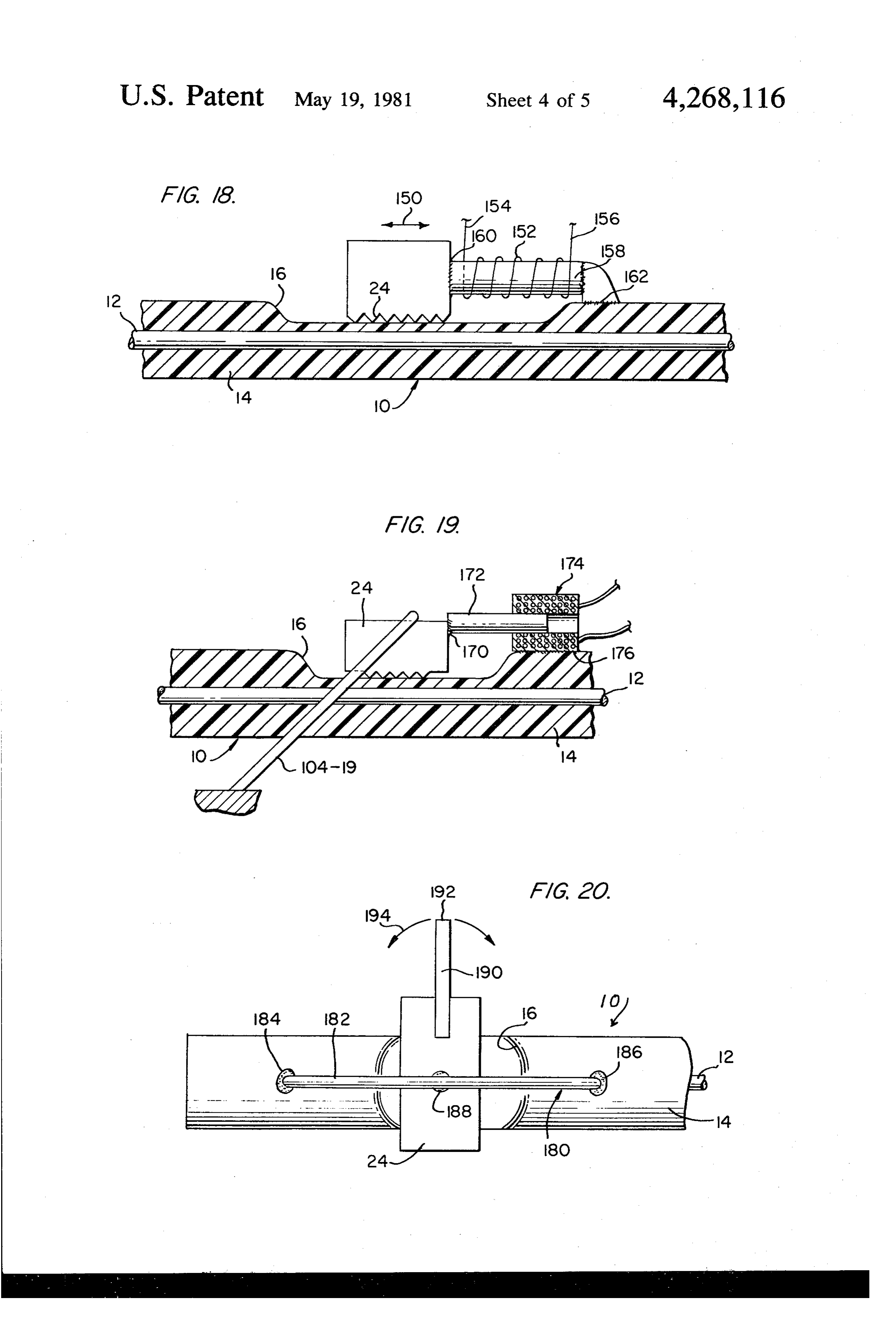
gas. The signal now in the gas will pass into the rigid 65 Referring to FIG. 18, the single mode fiber 10 con cylinder 112 of diameter A and then into the rigid tube sisting of the core 12 and cladding 14 is provided with 114 of diameter B. The junction of these two tubes is the usual ground zone 16. Within the zone 16 is "impedance transformer' and resembles a funnel 116. mounted a grating 24, the grating 24 is caused to move
Page 11
in the direction of the arrow 150 by an electrical coil to reflect a different laser wavelength line. Each grating 152 having leads 154 and 156. The coil creates a magnet or pair so formed can be coupled to a different parame field about the core 158 of magnetostrictive material. ter to be measured. A spectral analysis of the reflected The core is cemented as at 160 to the grating and at the light will reveal several frequency regions each corre opposite end as at 162 to the cladding 14. It will be 5 sponding to a different grating or pair of gratings. The recognized by those skilled in the art that the coil 152 is invention further causes the input laser light to be not needed when the unit is used to measure magnetic pulsed. Since each grating or pair of gratings is located fields. at a different distance, along the fiber as measured from Referring now to FIG. 19, the single mode fiber 10 is the laser, the reflected light from each grating or pair of provided with the ground zone 16 in its cladding 14, and 10 gratings will arrive back at the analyzing instrumenta in this zone is mounted the optical grating 24. The tion at different times. Correlating return time to dis mounting includes a quartz fiber or spider 104-19 as tance traveled by the laser pulse allows each return disclosed in reference to FIGS. 13 and 14. One end of pulse to be identified with a particular grating or pair of the grating 24 is cemented as at 170 to a core 172 mov gratings and therefore each return pulse will again indi able within solenoid coil 174 cemented as at 176 to the 15 cate a separate monitored condition. fiber cladding 14. We claim:
Now referring to FIG. 20, the optical fiber 10 having 1. Means for modulating radiant energy in a single a cladding 14 is provided with a ground zone 16 within mode clad optical fiber comprising:
which the optical grating 24 is mounted. The mounting means 180 includes a thin fiber 182 cemented as at 184 20 a single trol mode optical fiber having a modulation con zone where the cladding is partially removed and 186 to the external surface of the cladding 14. Be or formed with a decreased thickness relative to tween the ends of the fiber 182 is positioned the grating the remainder of the cladding; 24 and maintained in the desired position by cement 188. an optical grating;
Also cemented to the top surface of the grating 24 is an arm 190, the free end 192 of which is connected to, for 25 means zone for mounting the optical grating in the control with the crests of the optical grating posi example, the movable element of the solenoid shown in tioned generally normal to the optical axis of the FIG. 19 or movable sail 118 illustrated in FIGS. 15 and 16. Motion of the arm 190 adjacent its end 192 is shown fiber; and by directional arrow 194. This motion shown by arrow means for sliding the optical grating relative to the 194 is a rotation about the normal to the geometric 30 optical fiber to cause a narrow band of the radiant plane containing the grating. As previously described, electromagnetic energy in the optical fiber to be such a rotation modulates the center frequency of the modulated in phase and/or frequency. 2. The grating reflector. In such cases, also as previously men for displacing invention defined in claim 1 wherein the means tioned, the optical fiber may be multimode provided respect to the optic the optical grating longitudinally with optical coherence is maintained over the length of the 35 axis of the optical fiber comprises a grating. shear mode piezoelectric transducer. It is finally understood that for any low frequency or 3. The invention defined in claim 1 wherein the crests static conditions the gratings position can be coupled to and troughs of the grating are caused by the crests and any body whose length or size relates to the particular troughs of an acoustic surface wave. conditions to be measured, such as animal membranes as for4.displacing
The invention defined in claim 1 wherein the means the optical grating longitudinally with affected by changes in humidity.
In all cases of measurement such a system, which respect to the optic axis of the optical fiber comprises a moves a periodic perturbation in a glass fiber, allows the longitudinal mode piezoelectric transducer. 5. The invention defined in claim 4 wherein one end measurement of low level signals in the presence of high electric and magnetic fields and noise, as in the case of 45 of the longitudinal mode transducer is bonded to the eeg, ekg signals. optical fiber.
In cases where the distance between the sensor grat 6. The invention defined in claim 4 wherein the grat ing and the data gathering instrumentation in great, as in ing is an integral part of the longitudinal mode trans towed acoustic arrays, the invention provides for the ducer.
actual assembly of an optical demodulation stage inside 50 7. Means for modulating radiant energy in a single the fiber by placing two gratings having the same spa mode clad optical fiber comprising:
tial period on the fiber and separating them by a dis a single mode optical fiber having a modulation con tance as measured along the length of the fiber. The trol zone where the cladding is partially removed invention couples the relative position of the two grat or formed with a decreased thickness relative to ings to the particular condition to be monitored. A 55 the remainder of the cladding; spectral analysis of the light reflected by such an ar an optical grating;
rangement reveals a series of resonant peaks very much means for mounting the optical grating in the control like those of a Fabry Perot interferometer. Location or zone with the crests of the optical grating posi motion of these peaks within the spectrum is a direct tioned generally normal to the optical axis of the indication of the condition being monitored. m 60 fiber; and
In cases where many separate conditions are to be means for sliding the optical grating relative to the monitored, the invention provides for both frequency optical fiber to cause a narrow band of the radiant and time multiplexing. The invention injects the fiber electromagnetic energy in the optical fiber to be with multiline laser light as from an iodine laser as re modulated in phase and/or frequency, ported by R. L. Byer et al in Applied Physics Letters, 65 where the means for displacing the optical grating Vol. 20 No. 11; June, 1972, or a turnable dye laser. Each longitudinally with respect to the optic axis of the grating, or in the case employing the optical demodula optical fiber comprises a shear mode piezoelectric tion system, each pair of gratings are constructed so as transducer, and
Page 12
wherein the piezoelectric transducer has the grating tioned generally normal to the optical axis of the formed in one surface. fiber; and 8. The invention defined in claim 7 wherein the grat means for sliding the optical grating relative to the ing is metallized and forms one of the electrodes for the optical fiber to cause a narrow band of the radiant transducer. 5 electromagnetic energy in the optical fiber to be 9. Means for modulating radiant energy in a single modulated in phase and/or frequency, mode clad optical fiber comprising: wherein the means for longitudinally displacing the a single mode optical fiber having a modulation con optical grating is a temperature sensitive material. trol zone where the cladding is partially removed 13. The invention defined in claim 12 comprising a or formed with a decreased thickness relative to 10 tube which longitudinally expands and contracts when the remainder of the cladding; heated or cooled.
an optical grating; 14. Means for modulating radiant energy in a single means for mounting the optical grating in the control mode clad optical fiber comprising:
Zone with the crests of the optical grating posi a single mode optical fiber having a modulation con tioned generally normal to the optical axis of the 5 trol zone where the cladding is partially removed fiber; and or formed with a decreased thickness relative to means for sliding the optical grating relative to the the remainder of the cladding; optical fiber to cause a narrow band of the radiant an optical grating;
electromagnetic energy in the optical fiber to be means for mounting the optical grating in the control modulated in phase and/or frequency, Zone with the crests of the optical grating posi wherein the grating is rotated about the normal to the tioned generally normal to the optical axis of the geometric plane containing the grating in proportion to fiber; and an input signal. means for sliding the optical grating relative to the 10. Means for modulating radiant energy in a single optical fiber to cause a narrow band of the radiant mode clad optical fiber comprising: 25 electromagnetic energy in the optical fiber to be a single mode optical fiber having a modulation con modulated in phase and/or frequency, trol zone where the cladding is partially removed wherein a thin fiber is used to maintain the grating in or formed with a decreased thickness relative to close contact with the optical fiber. the remainder of the cladding; 15. Means for modulating radiant energy in a single an optical grating; mode clad optical fiber comprising: means for mounting the optical grating in the control a single mode optical fiber having a modulation con Zone with the crests of the optical grating posi trol zone where the cladding is partially removed tioned generally normal to the optical axis of the or formed with a decreased thickness relative to fiber; and the remainder of the cladding; means for sliding the optical grating relative to the 35 an optical grating;
optical fiber to cause a narrow band of the radiant means for mounting the optical grating in the control electromagnetic energy in the optical fiber to be zone with the crests of the optical grating posi modulated in phase and/or frequency, tioned generally normal to the optical axis of the wherein the means for longitudinally displacing the fiber; and grating is a microphone diaphragm attached to the grat 40 means for sliding the optical grating relative to the 1ng. optical fiber to cause a narrow band of the radiant 11. Means for modulating radiant energy in a single electromagnetic energy in the optical fiber to be mode clad optical fiber comprising: modulated in phase and/or frequency, a single mode optical fiber having a modulation con wherein the means for moving the grating is a magneto trol zone where the cladding is partially removed 45 strictive material.
or formed with a decreased thickness relative to 16. Means for modulating radiant energy in a single the remainder of the cladding; mode clad optical fiber comprising:
an optical grating; a single mode optical fiber having a modulation con means for mounting the optical grating in the control trol zone where the cladding is partially removed zone with the crests of the optical grating posi 50 or formed with a decreased thickness relative to tioned generally normal to the optical axis of the the remainder of the cladding;
fiber; and an optical grating;
means for sliding the optical grating relative to the means for mounting the optical grating in the control optical fiber to cause a narrow band of the radiant Zone with the crests of the optical grating posi electromagnetic energy in the optical fiber to be 55 tioned generally normal to the optical axis of the modulated in phase and/or frequency, fiber; and wherein the means for longitudinally displacing the means for sliding the optical grating relative to the optical grating is a hydroacoustic antenna attached to optical fiber to cause a narrow band of the radiant the grating and optical fiber. electromagnetic energy in the optical fiber to be 12. Means for modulating radiant energy in a single 60 modulated in phase and/or frequency, mode clad optical fiber comprising: wherein the means for moving the rating is an electric a single mode optical fiber having a modulation con Solenoid and a moving core.
trol zone where the cladding is partially removed 17. Means for modulating radiant energy in a single or formed with a decreased thickness relative to mode clad optical fiber comprising: the remainder of the cladding; 65 a single mode optical fiber having a modulation con an optical grating; trol zone where the cladding is partially removed means for mounting the optical grating in the control or formed with a decreased thickness relative to Zone with the crests of the optical grating posi the remainder of the cladding:
Page 13
an optical grating; erally normal to the optic axis of the optical fiber, means for mounting the optical grating in the control and causing sliding of the grating relative to the zone with the crests of the optical grating posi optic axis of the fiber, tioned generally normal to the optical axis of the wherein longitudinal displacement of the grating rela fiber; and tive to the optic axis of the fiber is carried out by attach means for sliding the optical grating relative to the ing the grating to the diaphragm of a microphone. optical fiber to cause a narrow band of the radiant 23. A method of modulating radiant electromagnetic electromagnetic energy in the optical fiber to be energy in phase and/or frequency in a single mode modulated in phase and/or frequency, optical fiber comprising:
wherein the grating is rotated about the normal to the 10 removing a portion of the cladding from a single geometric plane containing the grating so as to cause mode optical fiber having a cladding about the the grating to reflect a particular wavelength band or fiber;
electromagnetic radiant energy. mounting an optical grating on said fiber in the Zone 18. A method of modulating radiant electromagnetic where the portion of the cladding has been re energy in phase and/or frequency in a single mode 15 moved with the crests of the grating oriented gen optical fiber comprising: erally normal to the optic axis of the optical fiber, removing a portion of the cladding from a single and causing sliding of the grating relative to the mode optical fiber having a cladding about the optic axis of the fiber, fiber; wherein longitudinal displacement of the grating rela mounting an optical grating on said fiber in the zone 20 tive to the longitudinal axis of the fiber is carried out by where the portion of the cladding has been re attaching the grating to a movable element of a hydroa moved with the crests of the grating oriented gen coustic antenna.
erally normal to the optic axis of the optical fiber, 24. A method of modulating radiant electromagnetic and causing sliding of the grating relative to the energy in phase and/or frequency in a single mode optic axis of the fiber. 25 optical fiber comprising:
19. The method defined in claim 18 wherein longitu removing a portion of the cladding from a single dinal displacement of the grating relative to the optic mode optical fiber having a cladding about the axis of the fiber is carried out by directing an electrical fiber;
signal to a longitudinal mode piezoelectric transducer. mounting an optical grating on said fiber in the zone 20. A method of modulating radiant electromagnetic 30 where the portion of the cladding has been re energy in phase and/or frequency in a single mode moved with the crests of the grating oriented gen optical fiber comprising: erally normal to the optic axis of the optical fiber, removing a portion of the cladding from a single and causing sliding of the grating relative to the mode optical fiber having a cladding about the optic axis of the fiber, fiber; 35 wherein longitudinal displacement of the grating rela mounting an optical grating on said fiber in the zone tive to the longitudinal axis of the fiber is carried out by where the portion of the cladding has been re securing the grating to a thermally expandable or con moved with the crests of the grating oriented gen tractible element.
erally normal to the optic axis of the optical fiber, 25. A method of modulating radiant electromagnetic and causing sliding of the grating relative to the energy in phase and/or frequency in a single mode optic axis of the fiber, optical fiber comprising:
wherein longitudinal displacement of the grating rela removing a portion of the cladding from a single tive to the optic axis of the fiber is carried out by direct mode optical fiber having a cladding about the ing an electrical signal to a shear mode transducer. fiber;
21. A method of modulating radiant electromagnetic 45 mounting an optical grating on said fiber in the zone energy in phase and/or frequency in a single mode where the portion of the cladding has been re optical fiber comprising: moved with the crests of the grating oriented gen removing a portion of the cladding from a single erally normal to the optic axis of the optical fiber, mode optical fiber having a cladding about the and causing sliding of the grating relative to the fiber; 50 optic axis of the fiber, mounting an optical grating on said fiber in the zone wherein the grating is rotated in proportion to an input where the portion of the cladding has been re signal or parameter.
moved with the crests of the grating oriented gen 26. A method of frequency and/or phase modulating erally normal to the optic axis of the optical fiber, radiant energy in a single mode fiber wherein the grat and causing sliding of the grating relative to the 55 ing is formed by the crests and troughs of an acoustic optic axis of the fiber, surface wave formed in a piezo or ferro electric material wherein longitudinal displacement of the grating rela placed near the single mode fiber core. tive to the logitudinal axis of the fiber is carried out by 27. A method of claim 26 wherein the frequency of directing an electrical signal to a piezoelectric element. the acoustic surface wave is coupled to an input signal 22. A method of modulating radiant electromagnetic 60 or parameter.
energy in phase and/or frequency in a single mode 28. A method of modulating radiant electromagnetic optical fiber comprising: energy in phase and/or frequency in a single mode removing a portion of the cladding from a single optical fiber comprising:
mode optical fiber having a cladding about the removing a portion of the cladding from a single fiber; 65 mode optical fiber having a cladding about the mounting an optical grating on said fiber in the zone fiber;
where the portion of the cladding has been re mounting an optical grating on said fiber in the zone moved with the crests of the grating oriented gen where the portion of the cladding has been re
Page 14
moved with the crests of the grating oriented gen by directing an electrical signal to a longitudinal erally normal to the optic axis of the optical fiber, mode piezoelectric transducer, and and causing sliding of the grating relative to the wherein an electric solenoid and movable core are sub stituted for the longitudinal mode piezoelectric mate optic axis of the fiber, 5 rial.
wherein longitudinal displacement of the grating 30. Means for modulating radiant energy in a single relative to the optic axis of the fiber is carried out mode clad optical fiber comprising:
by directing an electrical signal to a longitudinal a single mode optical fiber having a modulation con mode piezoelectric transducer; and trol zone;
wherein a magnetostrictive material is substituted for 10 an optical grating;
the longitudinal mode piezoelectric transducer. means for mounting the optical grating in the control 29. A method of modulating radiant electromagnetic zone with the crests of the optical grating posi energy in phase and/or frequency in a single mode tioned generally normal to the optical axis of the fiber; and optical fiber comprising: 15 means for sliding the optical grating relative to the removing a portion of the cladding from a single optical fiber to cause a narrow band of the radiant mode optical fiber having a cladding about the electromagnetic energy in the optical fiber to be fiber; modulated in phase and/or frequency. mounting an optical grating on said fiber in the Zone 31. A method of modulating radiant electromagnetic where the portion of the cladding has been re 20 energy optical in phase and/or frequency in a single mode fiber having a control zone comprising:
moved with the crests of the grating oriented gen mounting an optical grating on said fiber in the Zone erally normal to the optic axis of the optical fiber, with the crests of the grating oriented generally and causing sliding of the grating relative to the normal to the optic axis of the optical fiber, and optic axis of the fiber, 25 causing sliding of the grating relative to the optic wherein longitudinal displacement of the grating axis of the fiber.
relative to the optic axis of the fiber is carried out
Provenance
- Collection
- Cited prior art
- Original PDF
- patentimages.storage.googleapis.com →
- Filed
- 1979-10-26
- Pages
- 14
- Method
- pdftotext (the PDF's own text layer) + pdftoppm 300dpi page scans
- Source
- Google Patents bibliographic record
- Granted
- 1981-05-19
- Inventors
- Donald Schmadel; William H. Culver; Gordon Gould; Optelecom Inc
- Transcribed from
- patentimages.storage.googleapis.com →