patent · US5513600
Water fuel converter for automotive and other engines
7 May 1996
Page 1 — bibliographic record
United States Patent (19) 11 Patent Number: 5,513,600 Teves 45 Date of Patent: May 7, 1996 54 WATERFUEL CONVERTER FOR 5,156,114 10/1992 Gunnerman ..................... 123/DIG. 12 AUTOMOTIVE AND OTHER ENGINES 5,231,954 8/1993 Stowe .............................. 123/DIG. 12 Primary Examiner-Erick R. Solis 76 Inventor: Attie Eye,
W. Level Ave., Attorney, Agent, or Firm-Barry A. Bisson
(21) Appl. No.: 290,598 Device and method of generating hydrogen from water and i. utilizing simultaneously the generated hydrogen gas as (22 Filed: Aug. 15, 1994 alternative fuel or supplemental for automotive and other Related U.S. Application Data engines as means to replace up to at least as much as 80% ea pplication Ua of the hydro-carbon fuels used by such engines. The hydro (63) abandoned,
Continuation-in-part of ser. No. 406,052, Sep. 11, 1989, and a continuation-in-part of Ser. No. 627,751, gen generating device comprises, an electrolytic cellor combination of two or more cells energized by a high
Dec. 14, 1990, abandoned. density direct current of as much as 5,000 amperes, such 51) Int. Cl. FO2B 43/08 electrical energy derived from the automotive engine by 52 U s C ... 123,3,123/DIG, 12. opic transforming mechanical energy to electrical energy by 58 Fi id fs a h. y 12313, DIG 12: means of a direct current generator. The electrolytic cell or 58) Field of Search ................................. 204fdiG 4 1. 25 cells is supplied by a continuous feed water supply system. • *s Increased capacities are possible due to high amperage loads (56) References Cited attainable by the electrolytic cell without overheating. This is necessary to produce the requisite amount of hydrogen gas
3,648,668 3/1972 Pacheco ..... . 23/DIG. 2 example, with a fuel mixture of hydrogen and only 20% by 4,099,489 7/1978 Bradley ...... . 23/DIG. 2 volume of the gasoline fuel usually used in the engine, after 4,271,793 6/1981 Valdespino . . 123/DIG. 12 a steady state condition is achieved. The electrolytic cell or 4,369,737. 1/1983 Sanders ...... ... 123/DIG. 2 cells are equipped with means to control energy load, water 4,763,610 8/1988 Thomas. ... 123/DIG. 2 flow, gas flow, gas pressure, and presenting the hydrogen gas 4,773,981 9/1988 Bidwell ....................................... 123/3 fuel into the combustion chambers of the automotive and 5,105,773 4/1992 Cunningham et al. ... 123/DIG. 12 other engines.
5,119,768 6/1992 Russell ............................ 123/DIG. 12 5,143,025 9/1992 Monday .......................... 123/DIG. 12 4 Claims, 6 Drawing Sheets
Page 2
Drawing sheet — no readable text.
Page 3
Drawing sheet — no readable text.
Page 4
Drawing sheet — no readable text.
Page 5
Drawing sheet — no readable text.
Page 6
Drawing sheet — no readable text.
Page 7
Drawing sheet — no readable text.
Page 8
WATERFUEL CONVERTER FOR hydroxide (30% NaOH), which is prohibitively expensive AUTOMOTIVE AND OTHER ENGINES when compared to the cost of pure gasoline or diesel fuel. All these schemes of hydrogen generation share two serious
This application is a continuation-in-part of the applica problems: 1) the generator is not designed to operate a tion of ANTONIO Y. TEVES, Ser. Nos. 71406,052 and continuous feed system necessary to increase output or 07/627,751, filed Sep. 11, 1989, and Dec. 14, 1990, both production of hydrogen from the cell; 2) the hydrogen abandoned. generator is not designed to operate at high current densities In this application, unless otherwise specified, percent in order to produce sufficient hydrogen to replace at least ages are liquid volume percent. about 80% of the hydrocarbon fuel used by automotive and 10 other engines.
BACKGROUND OF THE INVENTION Another invention (U.S. Pat. No. 4,609,120) dealt with photoelectrolytic production of hydrogen only on a very 1. Field of the Invention limited scale, but this method is not commercially viable and This invention relates to an efficient water fuel converter not applicable to automotive and other engines. which converts water into hydrogen and oxygen whereby 15 Still another invention (U.S. Pat. No. 4,099,489 by Bra the generated hydrogen gas is utilized simultaneously as an dley) deals with generation of hydrogen in small quantities alternative fuel to replace up to at least 80% of the hydro to be combined with the hydrocarbon fuel whose prime carbon fuels or other synthetic fuels with the hydrogen fuels purpose is reduction of pollution, but not to replace at least used by automotive and other engines. For example, the fuel 20 about 80% of the petroleum fuels used by automotive and generated from the system can replace up to 80% of the other engines. This patent has several drawbacks and dis volume of gasoline admixture normally used in an automo advantages, including the following: 1) the method utilizes bile engine. Recycle of the oxygen to the combustion expensive equipment such as turbine, high pressure pumps, chamber can reduce undesirable combustion byproducts, water purifier, flow and pressure control instruments, D.C. such as nitrogen oxide.
25 and A.C. generators, condenser, etc., in addition to the costly 2. Description of the Prior Art high pressure electrolytic cell used; 2) the method employs Several patents pertaining to utilization of hydrogen gas two sets of generators and a rectifier unit which complicates as a source of fuel for automotive and other engines were not transformation of energy from mechanical to electrical well-appreciated by vehicle owners because of several draw energy thereby greatly reducing overall efficiently; 3) the backs, disadvantages, and inherent defects in the system. 30 complex method and equipment used in producing a small Some were very cumbersome, utilizing the ready-made quantity of hydrogen to replace an even small portion of hydrogen contained in heavy steel cylinders (U.S. Pat. Nos. hydrocarbon fuel required to run the engine with the object 4,508,084; 3,983,882; 4,178,882), while others dealt with of simply reducing the pollutant emissions to a very small generation of hydrogen on a very limited Scale insufficient to degree will result in a prohibitively high fuel cost; 4) the replace a majority (and even at least about 80%) of the total 35 pollutant effect of the hydrocarbon fuel still present in the volume of fuel requirements of automotive and other combustion process will remain unabated and will continue engines. Other patents (U.S. Pat. Nos. 4,597,363; 4,368,696; to be a problem; 5) no laboratory test on the emissions of the 4,489,864; 3,458,412; 3,242,665; 4,203,814), generate very exhaust of an engine using Bradley's method have been limited quantities of hydrogen from chemicals and other conducted or reported.
sources insufficient to supply a majority to at least about 40 Considering the drawbacks of Bradley's invention and 80% of the total fuel needs of automotive engines. Still other cited in the foregoing, the best alternative to conserve another invention (U.S. Pat. No. 4,036,181) describes the the energy resources of the United States and eliminate use of metal hydrides, particularly magnesium hydride, in pollution is to replace a major portion (e.g. 81%) of the generating hydrogen gas as fuel for automotive engines. hydrocarbon fuel with relatively non-pollutant fuel such as However, the drawbacks of this invention are: 1) the metal 45 hydrogen, which is the object of the present invention. hydride is expensive; 2) the process of generating hydrogen is complicated and involves costly equipment; and 3) the method of refueling is inconvenient and time-consuming. SUMMARY OF THE INVENTION Further, the process of regenerating the spent hydride When percentage is expressed herein it refers to percent involves costly and complex operations. 50 by volume. The present invention comprises utilizing an Another invention (U.S. Pat. No. 4,763,610) relates to a efficient hydrogen generator to convert water into hydrogen gas generator which generates hydrogen from a 30% solu and oxygen in sufficiently large quantities capable of sup tion of sodium hydroxide (30% NaOH). The generated plying (at steady state) a major percentage up to at least hydrogen is not utilized directly, but is subsequently mixed about 80% of the volume of fuel normally required by an with the petroleum-based fuel in an engine component 55 automotive or other internal combustion engine by passing before it can run an engine. This method has several draw a high density direct current through water contained in an backs, among which are the following: 1) the gas generating electrolytic cell or water fuel converter, in the range of 50 to device has a limited capacity because it can only generate a 5,000 amperes, whereby the generated hydrogen is utilized small amount of hydrogen gas that can not replace at least simultaneously by the automotive or other engines, the about 80% of the petroleum fuel needed by the automotive 60 hydrogen gas passing through a flash back preventer, and engine; 2) the products of combustion still contain appre thence into a hydrogen gas collector tank, carburetor adapter ciable amounts of pollutants due to the higher proportion of and finally to the carburetor of the gasoline engine. For petroleum base fuel present; e.g., (CO 0.7%; NO 28.9%; diesel and other fuel injection types of engines, the hydrogen unburnt hydrocarbon fuel 13.8%). The large amount of gas is simply introduced into the respective fuel lines of unburnt hydrocarbon fuel not only increases pollution, but is 65 these engines. For gas turbine engines, the hydrogen gas is actually energy lost in the combustion process; 3) the introduced directly into the combustion chamber of the process involves relatively high concentration of sodium engine.
Page 9
The drawbacks of the inventions mentioned in the pre by-side with the carburetor of a gasoline engine to convert ceding Description of the Prior Act (U.S. Pat. No. 4,763,610 the engine from gasoline (liquid) feed to hydrogen gas (gas) and others) are solved or overcome in the present invention feed by means of a two-way fuel selection valve and by incorporating the following features: 1) the electrolytic Y-connection element. In such manner, the gasoline fuel can cell or cells in the present invention are designed for a be decreased or even shut off simultaneously and hydrogen continuous feed system which enables the cells to maintain gas introduced without stopping the engine. For diesel, gas the anodic level necessary for safe operation even at high turbine and other fuel injection type of engines, no carbu amperage loads or high current densities in the range of 50 retor adapter is required because the hydrogen gas is simply to 50,000 amperes; 2) the direct current supply used is in the introduced into the fuel lines of these engines by means of range of 50 to 5,000 amperes, which amperage is capable of 10 the two-way fuel selection valve and Y-connection element generating sufficient hydrogen gas fuel which can supply (at with appropriate means to present the hydrogen gas (and, if steady state), a majority up to at least about 80% of the total desired, the oxygen) into their respective combustion cham liquid volume fuel needs of automotive and other engines. bers.
One object and advantage of this invention is that the At the initial start-up, the engine is run first with the emissions resulting from the combustion of hydrogen are 15 gasoline fuel available, but as soon as sufficient amount of relatively non-pollutant, thereby greatly reducing CO and hydrogen gas is stored in the hydrogen gas collector tank, unburned hydrocarbons by as much as 65%. Still another the gasoline fuel gradually is closed to a point where only advantage of internally generated hydrogen as a primary 19% of the gasoline fuel is left in admixture with 81% of the source of fuel and recycling the generated oxygen is the gasoline fuel originally used before introduction of hydro reduction of undesirable nitrogen pollutants due to the 20 gen gas, while simultaneously opening the hydrogen gas decreased consumption of air as an oxygen source. fuel into the combustion chamber of the engine. For an LPG A feed pump continuously supplies water into the elec gas fuel operated engine in use, the automatic switching trolytic cell, passing through a feed tank and a constant level mechanism with the two-way fuel selection valve and and flow control device to maintain anodic level inside Y-connection element is simply used to change from the anodic chamber while excess water flows back to the sump 25 throttle and adjust the LPG gas valve which is mixed with tank by way of outlets at the bottom of the cathodic the hydrogen gas fuel generated from the cells at any point chambers. along the fuel line.
The electrolytic cell is designed as a compact unit, com For subsequent start ups, the hydrogen gas stored in the prising a rectangular body or frame made of material such as 30 hydrogen gas collector tank could be able to run the engine bakelite, a graphite carbon anode perforated and grooved for easily with the minimal supplement of gasoline (i.e. 19%) fast and easy circulation of anolyte water inside the anodic diesel fuel, or LPG gas. In the automobile, the water sump compartment; a perforated steel cathode with back up com tank is simply installed beside the gasoline tank, while the partment to hold the hydrogen gas and cathodic liquid; a set electrolytic cell is installed as a compact unit in the back of asbestos diaphragms to separate the anodic from the 35 compartment of the car.
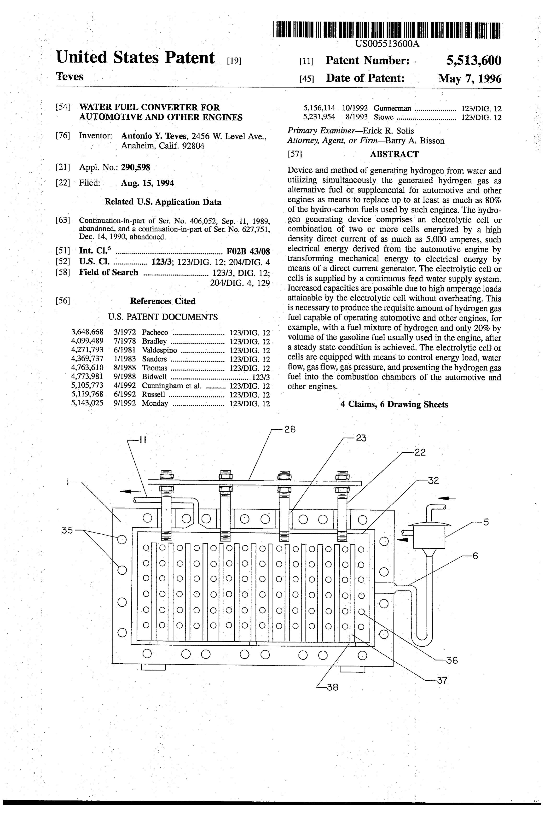
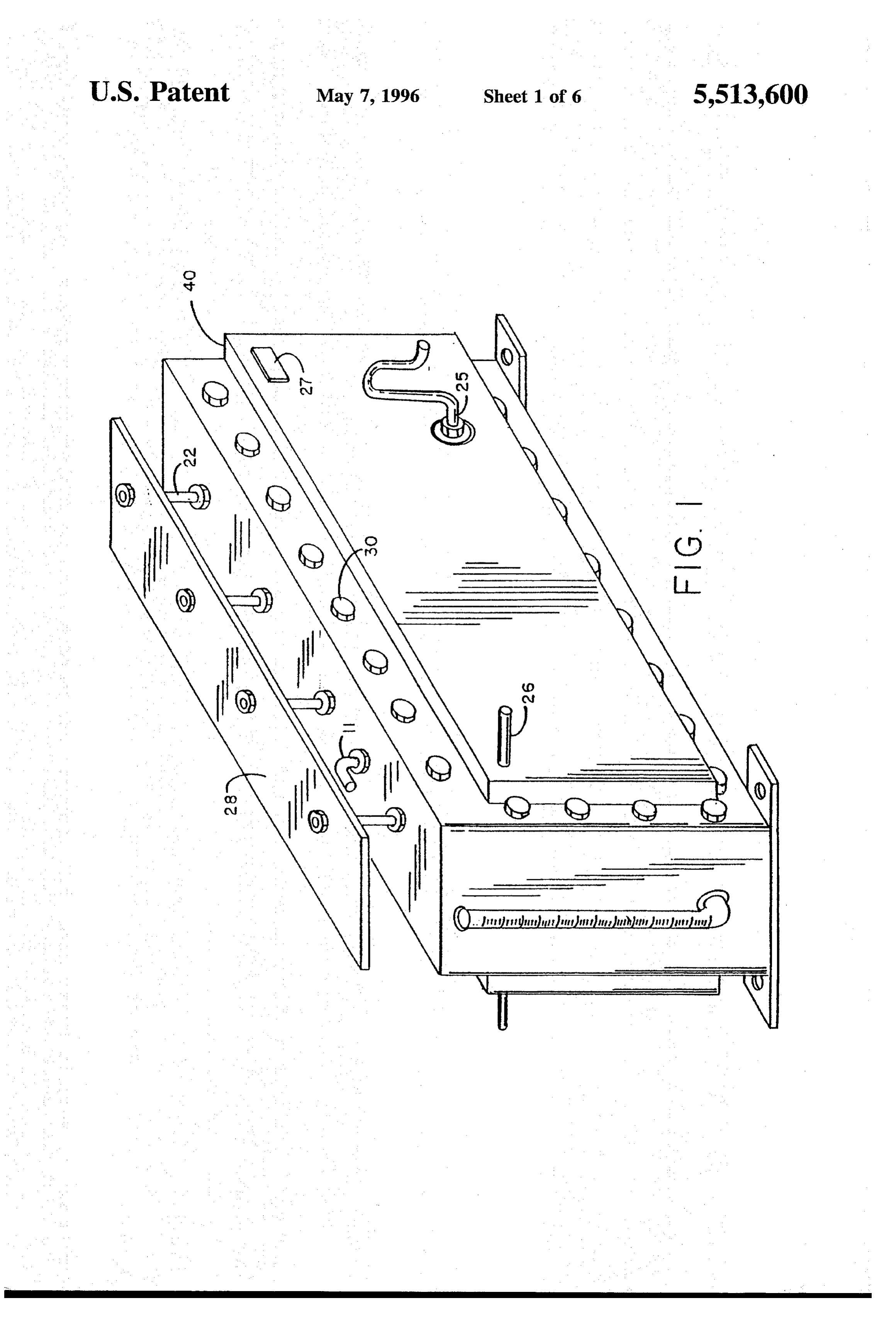
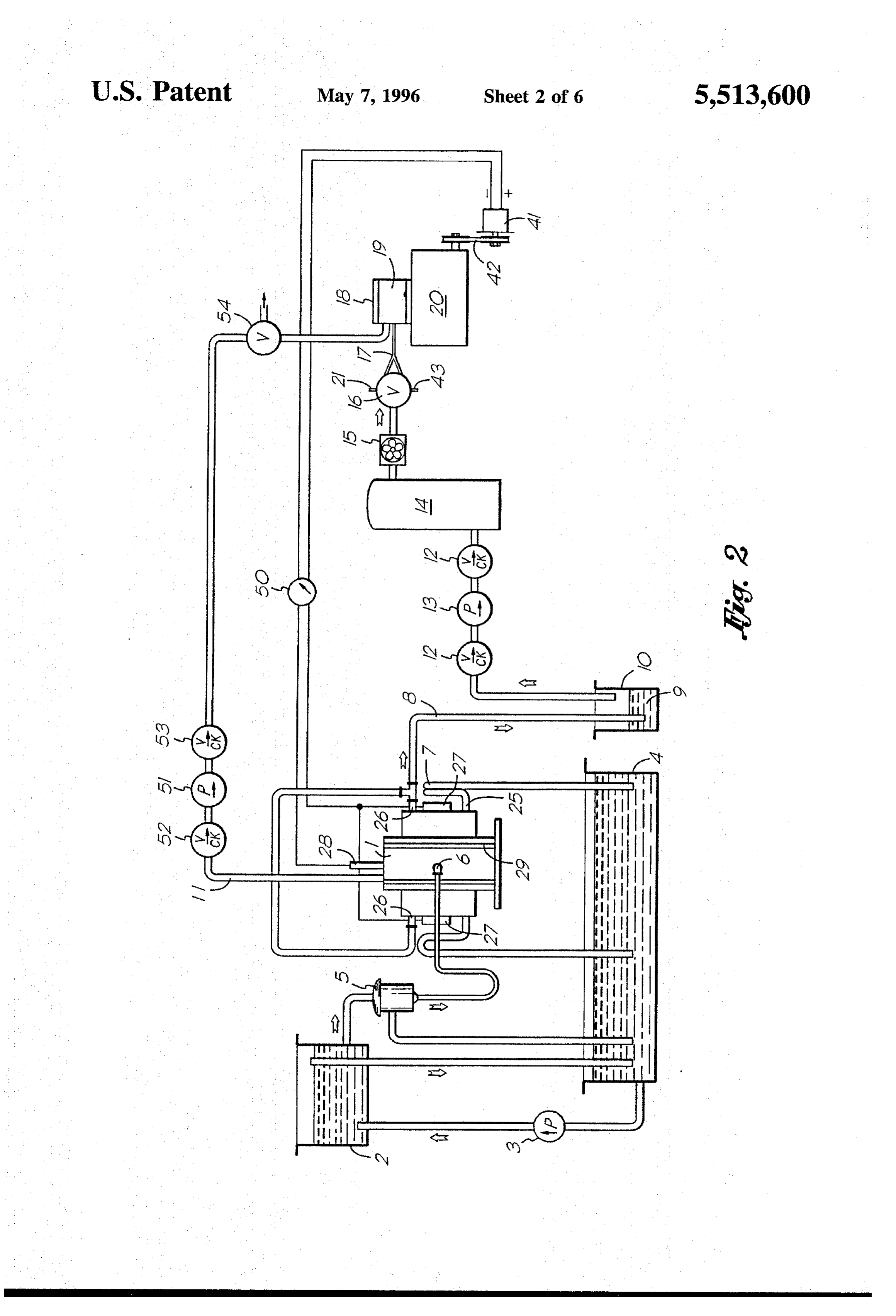
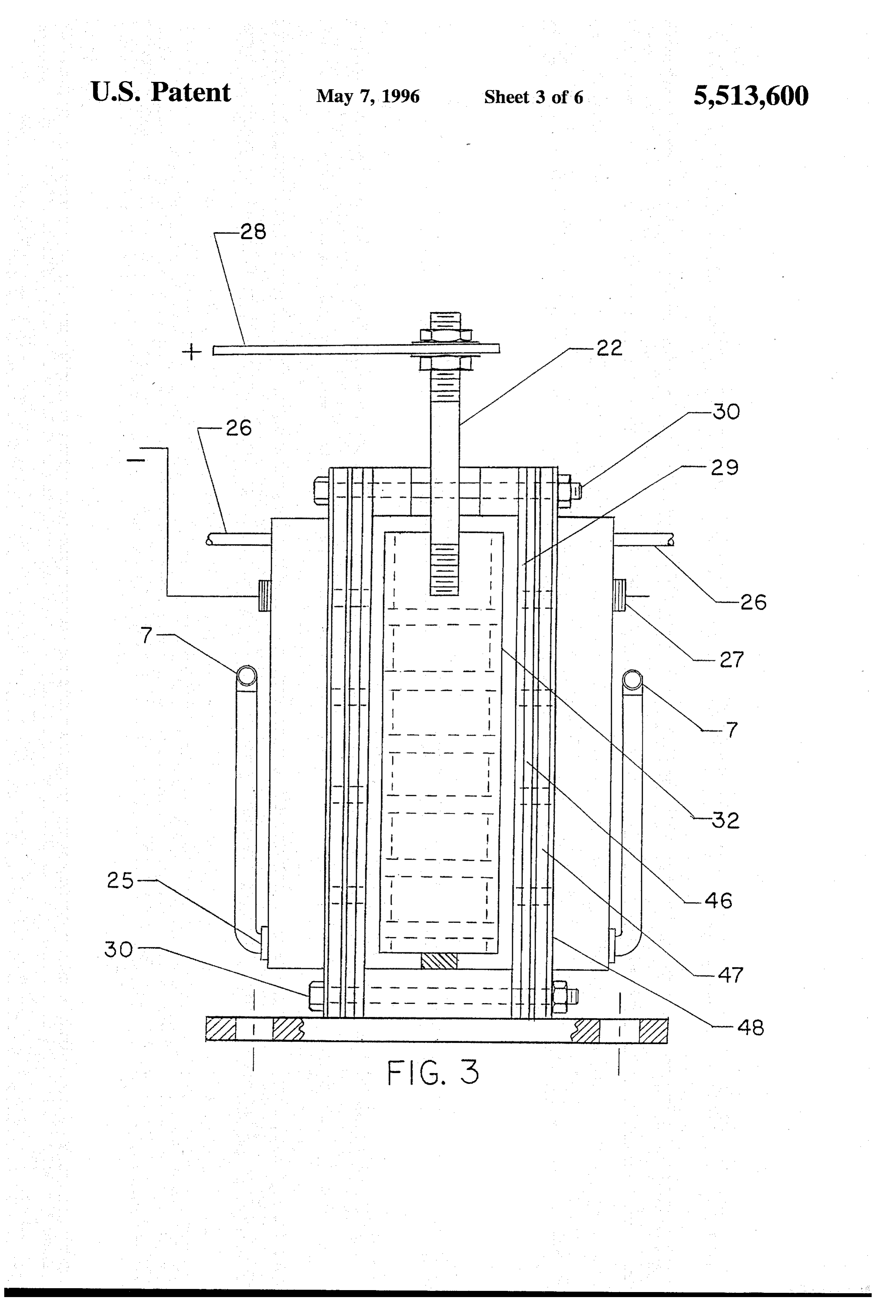
cathodic compartments placed at both sides of the frame In operation, water is first treated with an alkali to obtain fitted with gaskets at both sides to form a tightly sealed inner a pH range of 7.1-14. The water, thus activated, is fed and outer compartment which are bolted together with the continuously into the electrolytic cell from a feed tank cathodic plates in place. through a constant level flow control device, the feed tank The graphite carbon anode is fitted loosely into the frame 40 being supplied continuously with activated water from the so that water can continuously enter the anodic compartment sump tank by means of a 6-12 volts D.C. electric pump. of the cell; the mild steel comprising the cathodic chambers High density direct current in the order of 50–5,000 amperes has holes at the bottom for excess water to pass through the is then supplied to the electrolytic cell through the respective sump tank, while holes at the top of the cathodic chambers anode and cathode connections with current density adjusted serve as exit for the hydrogen gas to pass through continu 45 by means of a variable power supply control device to ously into the flash back preventer, thence to the hydrogen provide the amperage loads required for a particular auto gas collector tank and finally into the carburetor through the motive engine model and horsepower. The hydrogen gas carburetor adapter of the carburetor type of engine and gas generated from the cell is utilized simultaneously by the turbine engines by way of the two-way fuel selection valve automotive engine passing through the exit tube, flash back and Y-connection element of the routing device. Similarly, 50 preventer, then to the hydrogen gas collector tank, two-way the generated oxygen can be recycled to reduce the quantity fuel selection valve, Y-connection element, carburetor of air needed for combustion (at steady state). By "steady adapter, and finally to the carburetor of the automotive state' is meant the operation of the engine combustion after engine; e.g., with minimal supplement of gasoline, diesel, or start-up and sufficient operation to achieve generation of LPG gas. The oxygen, liberated and separated at the anodic sufficient hydrogen to replace at least about 81% of the 55 compartment, is pumped by a D.C. electric pump to the volume of gasoline normally used at that point in the carburetor of the engine or, less desirably, simply vented into operation of the engine. Although there is a consumption of the atmosphere. Check valves before and after the pump energy in converting gasoline to electricity, and water to provide safety measures to prevent back flushing. hydrogen, the advantages of the invention overcome this loss by an overall more efficient combustion. 60 BRIEF DESCRIPTION OF THE DRAWINGS The water fuel converter includes an electrical power source or supply such as a direct current generator of FIG. 1 is a Perspective of the Water Fuel Converter. 50-5,000 amperes direct current output rating run by the FIG. 2 is a Schematic Diagram showing the complete automotive engine connected by means of a rotational set-up of the device for generating hydrogen from water and energy connecting element. 65 presenting the hydrogen gas to the engine. This invention operates initially during start-up on a dual FIG. 3 is a cross-sectional view of the Electrolytic cell feed system whereby the carburetor adapter is fitted side showing the position of the graphite carbon anode in the
Page 10
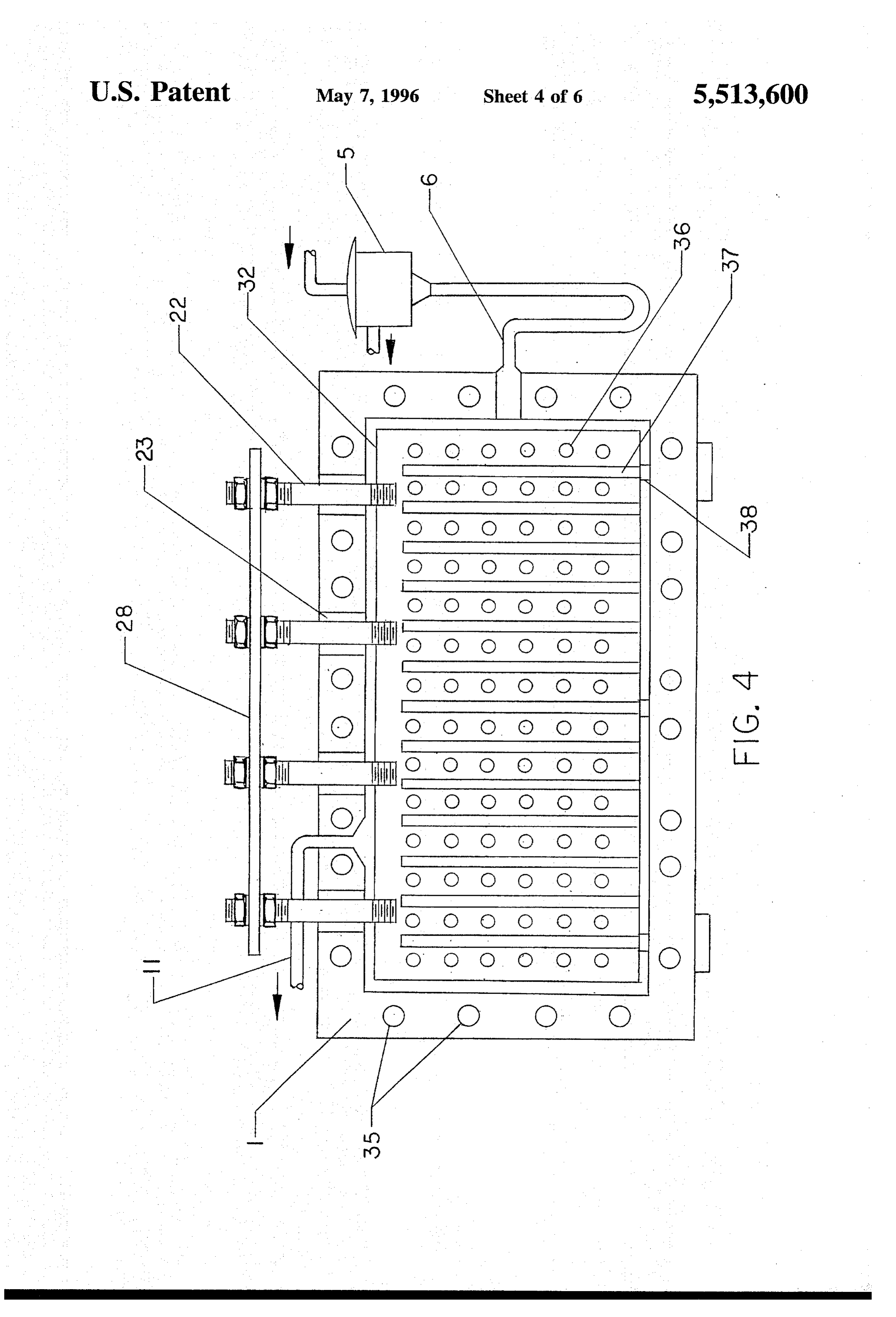
anodic chamber, connection of the positive terminal to the the anodic chamber by natural convection currents resulting graphite carbon anode, and arrangement of the diaphragms in a rapid dissipation of heat in the system. The location of and gaskets with respect to the two cathodic chambers. the inlet feed (6) also facilitates the rise of heated water FIG. 4 is a longitudinal section of the Electrolytic cell thereby providing a fresh supply of water in the system showing the respective positions of the copper rods connec which is readily decomposed by the flow of the high density tion the graphite carbon anode and the position of the direct current through it.
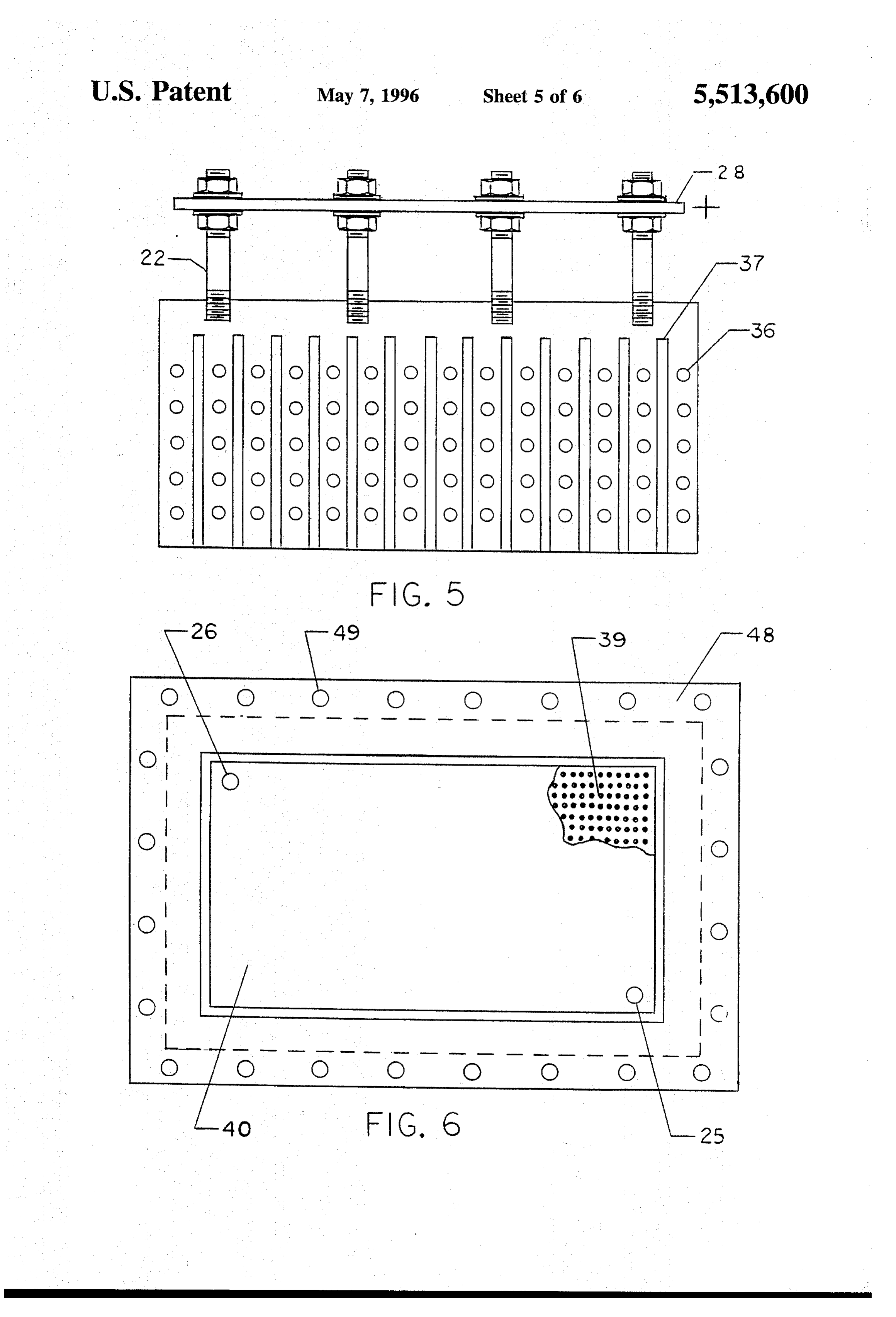
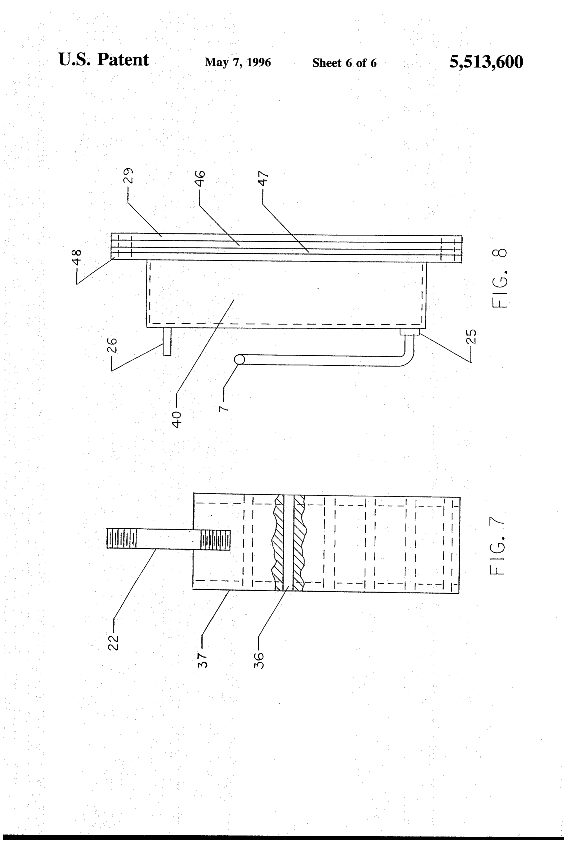
constant level control device. The frame of the electrolytic cell (1), (FIG. 4), is provided FIG. 5 is a longitudinal section of the graphite carbon with bolt holes (35) around the periphery of the frame to anode with perforations and grooves shown in detail. allow studbolts at both sides of the frame, firmly anchoring 10 the asbestos diaphragms (46), (FIG. 8). The graphite carbon
FIG. 6 is a front view of the cathodic plate and chamber, with cut-away view showing the perforations of the inner anode (32), (FIG. 4) is supported by porcelain supports (38) plate. to avoid grounding or short-circuiting of the cell and is FIG. 7 is a detailed cross-section of the graphite carbon connected to the outside positive terminal circuit of the d.c. anode. generator (41) by means of copper rods (22) threaded at both
FIG. 8 is a detailed cross-section of the cathodic chamber ends, one end of which is screwed tightly to the graphite showing arrangement of the diaphragms, gaskets, and carbon anode (32) spaced at convenient intervals along the cathodic liquid discharge pipe. axis while the external ends of the copper rods (32) are attached to the copper bus bar (28) which is electrically
connected to the d.c. generator (41) which is driven by the
PREFERRED EMBODIMENTS automotive engine (20) by means of the rotational energy connecting element (42).
Reference FIG. 2, (1) is the Electrolytic cell which The cathodic steel plate (40), (FIG. 6) is shown with generates hydrogen from water as water is fed continuously perforations (39) in the cut-away view. A clamp (48) is fitted from a feed tank (2) maintained at constant head by a feed snugly around the rectangular body of the cathodic chamber, pump (3) while excess water flows back to the sump tank with bolt holes (49) for the bolts to pass and hold firmly the (4). Water is fed continuously to the Electrolytic cell (1) gaskets (29), asbestos diaphragms (46) and cathodic plates through a constant level flow control device (5) by way of (47), (FIG. 8).
the inlet hole (6). Excess water flows back to the sump tank The negative terminal (27) of the cathode (FIG. 1) is (4) through discharge holes (5) of the cathodic liquid level 30 connected electrically to the negative terminal of the d.c. control device (7). generator (41). Means to adjust and regulate the power load The Electrolytic cell is energized by a direct current (d.c.) to the electrolytic cell with a variable power supply control generator (41) of 50-5,000 amperes d.c. current output, run device (50). (FIG. 2) are connected between the electrolytic by the automotive engine (20) by means of a rotational cell (1) and the d.c. generator (41) enabling the cell to energy connecting element (42). The positive terminal of the 35 operate at varying amperage loads adaptable to each par d.c. generator (41) is connected to the bus bar (28) of the ticular engine model and horsepower rating in order to graphite carbon anode (32) while the negative terminal is generate the requisite amount of hydrogen gas which is connected to the negative (27) of the cathodic plate. added to (as by mixing) with the gasoline, diesel fuel, or As current is supplied to the electrolytic cell (1), water LPG gas required to operate such engine. inside the cell is immediately decomposed into hydrogen 40 The oxygen gas coming from the exit tube (11) is pumped and oxygen, the hydrogen gas passing through the hydrogen by means of a pump (51) provided with check valves (52) outlet (26) while the separated oxygen from the anodic and (53) to maintain pressure inside anodic chamber which chamber is discharged through the oxygen exit tube (11). is presented to the carburetor (18) or simply vented into the The hydrogen gas from the hydrogen outlet (26) flows atmosphere by means of the two-way valve (54). continuously through conduit (8) leading to the flash back 45 Although the description above contains many specifici preventer (10) containing water (9) maintained at a prede ties, these should not be construed as limiting the scope of termined level, then through check valves (12) and (12) and the invention but as merely providing illustrations of some finally into the hydrogen gas collector tank (14). Pressure of the presently preferred embodiments of this invention. inside the anodic chamber of the electrolytic cell (1) and For example, the d.c. generator may vary over the range of pressure at the hydrogen gas collector tank (14) are main 50 50-5,000 amperes. The anode could be fabricated from tained at a certain point by means of the 6-12 volts d.c. nickel or appropriate metallic element, and the diaphragms electric pump (13). Hydrogen from the hydrogen gas col could be any other acid-alkali resistant filtering material. lector tank (14) is introduced into the engine by means of the The hydrogen gas an be routed by an electric blower, and pump (15), the hydrogen gas passing through the two-way fuel injection nozzles could replace the carburetor. The fuel selection valve (16) connected with Y-connecting ele 55 cathodic steel plate could be fabricated from stainless steel ment (17) and thence through the carburetor adapter (18) to or other appropriate metallic element. the carburetor (19) and finally to the combustion chamber of the automotive engine (20) inlet (21) for gasoline fuel and EXAMPLE inlet (43) for LPG gas fuel are provided in the fuel selection valve (16) to enable presenting to hydrogen gas simulta 60 A Wisconsin engine was started with gasoline fuel to neously while maintaining the desired or requisite propor drive a direct current generator feeding electrical power to tions; e.g., about 19% of the volume of gasoline feed with electrolytic cells. While the engine was running on pure the remainder of fuel being hydrogen gas, the energy equiva gasoline fuel, the hydrogen generated from the cells was lent of LPG gas feed and the remainder hydrogen. vented to the atmosphere and the rate of gasoline consump The anode (32), FIGS. 3 and 4, is made of graphite 65 tion was determined. Then the hydrogen was introduced into carbon, perforated (36) and grooved (37) to allow free the engine by way of a T-connection, and through a valve, circulation of activated water from the bottom to the top of and gradually closing the gasoline fuel petcock valve to a
Page 11
point where the engine could continue running with the means for routing the hydrogen gas to the engine; gasoline and hydrogen fuel mixture. Attempts were made to means for generating a high density direct current Source completely close or shut off the gasoline fuel and run the to power the converting means whereby said hydrogen engine with 100% hydrogen fuel, but the engine stopped. gas will serve as the major fuel source to replace, at The engine was made to run with the minimal mixture of steady state, a majority of the volume of gasoline gasoline combined with the total volume of hydrogen gen normally used by said engine; erated from the electrolytic cells, and the engine was made to run with this combined gasoline and hydrogen fuel and wherein said electrolytic cell is composed of a mixture for a period of 12 minutes. The rate of flow of water-tight frame, a positively charged graphite carbon gasoline fuel used to supplement the hydrogen fuel to keep 10 anode, said anode being perforated and grooved, a the engine running normally was also measured. negatively charged perforated steel cathode, whereby In the hydrogen run, 81 volume percentless gasoline was the flow of electrolyte through the cell is facilitated, and used at steady state. The "gasoline only' test was run under asbestos diaphragms as means for separating the anodic a "no load' condition while the "gas/H2 mixture' test was from the cathodic compartments. run under a "load' condition. This was because the "load' 15 2. The apparatus of claim 1, in which the means for was the actual charging of the electrolytic cells, and a routing the hydrogen gas to the engine comprises a flash "gasoline only” condition required no charging of electro back preventer, a hydrogen gas collector tank, a two-way lytic cells. fuel selection valve, a Y-connecting element, and a carbu Analysis of the exhaust gases showed, in volume percent, 20 retor adapter whereby the engine may be run, at steady state, with gasoline only 8.84% CO, 0.87% total hydrocarbons, on hydrogen and less than 50% of the volume of the gasoline and NOx of 44.1 ppmv. The hydrogen and gasoline rune normally required to power said engine. showed 3.20% CO, 0.36% total hydrocarbons, and 283.0 3. The apparatus of claim 1, in which the means for ppmv NOx. The NOx can be greatly lowered in the present generating a current source to power the converting means invention by recycling the generated oxygen to the engine. comprises a direct current output in the range of 50-5,000 The scope of this invention should be determined by the amperes.
appended claims and their legal equivalents, rather than by 4. The apparatus of claim 1, where the current generating the examples given. means, further comprises a positive output which is con I claim: nected to the anode of the electrolytic cell, and a negative 1. An apparatus for converting water into fuel for auto 30 output which is connected to the cathode of the electrolytic motive or other combustion engine comprising: cell, whereby the converting means is accomplished. means, within an electrolyte cell, for converting water into hydrogen gas and oxygen gas; ck k k k
Provenance
- Collection
- Cited prior art
- Original PDF
- patentimages.storage.googleapis.com →
- Filed
- 1994-08-15
- Pages
- 11
- Method
- pdftotext (the PDF's own text layer) + pdftoppm 300dpi page scans
- Source
- Google Patents bibliographic record
- Granted
- 1996-05-07
- Inventors
- Antonio Y. Teves
- Transcribed from
- patentimages.storage.googleapis.com →