patent · US5156114
Aqueous fuel for internal combustion engine and method of combustion
20 October 1992
Page 1 — bibliographic record
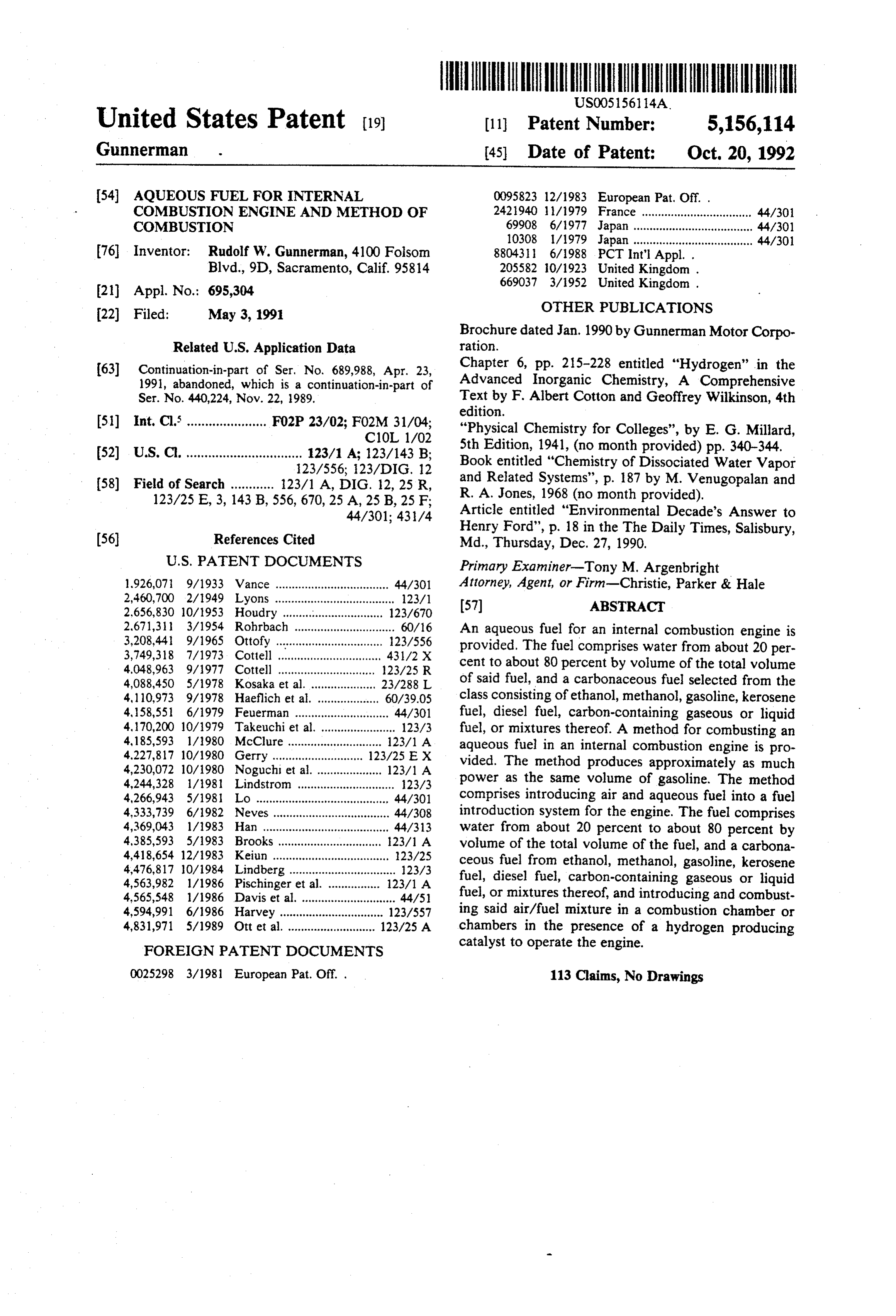
United States Patent (19) 11 Patent Number: 5,156,114 Gunnerman . (45) Date of Patent: Oct. 20, 1992 54 AQUEOUS FUEL FOR INTERNAL 0095823 12/1983 European Pat. Off. . COMBUSTION ENGINE AND METHOD OF 2421940 l/1979 France .................................. 44/30 COMBUSTION 69908 6/1977 Japan ...... ... 44/301 10308 1/1979 Japan ..................................... 44/301 76 Inventor: Rudolf W. Gunnerman, 4100 Folsom 8804311 6/1988 PCT Int'l Appl. . Blvd., 9D, Sacramento, Calif. 95814 205582 10/1923 United Kingdom.
(21) Appl. No.: 695,304 669037 3/1952 United Kingdom . 22 Filed: May 3, 1991 OTHER PUBLICATIONS Brochure dated Jan. 1990 by Gunnerman Motor Corpo
Related U.S. Application Data ration.
(63) Continuation-in-part of Ser, No. 689,988, Apr. 23, Chapter 6, pp. 215-228 entitled "Hydrogen' in the 1991, abandoned, which is a continuation-in-part of Advanced Inorganic Chemistry, A Comprehensive Ser. No. 440,224, Nov. 22, 1989. Text by F. Albert Cotton and Geoffrey Wilkinson, 4th edition.
51) Int, Cl. ...................... F02P 23/02; F02M 31/04; "Physical Chemistry for Colleges', by E. G. Millard,
52 U.S. C. ................................ 123/1 A; 123/143 B; 5th Edition, 1941, (no month provided) pp. 340-344. 123/556; 123/DIG. 12 Book entitled "Chemistry of Dissociated Water Vapor (58) Field of Search ............ 123/1 A, DIG. 12, 25 R, and Related Systems", p. 187 by M. Venugopalan and 123/25 E, 3, 143 B, 556, 670, 25 A, 25 B, 25 F; R. A. Jones, 1968 (no month provided). 44/301; 431/4 Article entitled "Environmental Decade's Answer to
Henry Ford', p. 18 in the The Daily Times, Salisbury, (56) References Cited Md., Thursday, Dec. 27, 1990.
1.926,071 9/1933 Vance ................................... 44/301 Attorney, Agent, or Firm-Christie, Parker & Hale 2,460,700 2/1949 Lyons ...... ..., 123/l (57) ABSTRACT 2,656,830 10/1953 Houdry ... 123/670 2,671,311 3/1954 Rohrbach ............................... 60/16 An aqueous fuel for an internal combustion engine is 3,208,441 9/1965 Ottofy.... ... 123/556 provided. The fuel comprises water from about 20 per 3,749,318 7/1973 Cottell ..., ..., 431/2 X cent to about 80 percent by volume of the total volume 4.048,963 9/1977 Cottell ......... ... 23/25 R 4,088,450 5/1978 Kosaka et al. .................... 23/288 L of said fuel, and a carbonaceous fuel selected from the 4,110,973 9/1978 Haeflich et al. ................... 60/39.05 class consisting of ethanol, methanol, gasoline, kerosene 4, 58,551 6/1979 Feuerman ............................. 44/301 fuel, diesel fuel, carbon-containing gaseous or liquid 4, 170,200 10/1979 Takeuchi et al. ....................... 123/3 fuel, or mixtures thereof. A method for combusting an 4,185,593 1/1980 McClure ............................. 123/1 A aqueous fuel in an internal combustion engine is pro 4.227,817 10/1980 Gerry .............. ... 123/25 E X vided. The method produces approximately as much 4,230,072 10/1980 Noguchi et al..................... 123/1 A power as the same volume of gasoline. The method 4,244,328 1/1981 Lindstrom .............................. 123/3 4,266,943 5/1981 Lo ............... ... 44/301 comprises introducing air and aqueous fuel into a fuel 4.333,739 6/1982 Neves ...... ... 44/308 introduction system for the engine. The fuel comprises 4,369,043 1/1983 Han ......... ... 44/33 water from about 20 percent to about 80 percent by 4,385,593 5/1983 Brooks ... 123/1 A volume of the total volume of the fuel, and a carbona 4,418,654 12/1983 Keiun ...... ... 23/25 ceous fuel from ethanol, methanol, gasoline, kerosene 4,476,817 10/1984 Lindberg................................. 123/3 fuel, diesel fuel, carbon-containing gaseous or liquid 4,563,982 1/1986 Pischinger et al. . 123/1 A 4.565,548 1/1986 Davis et al. ..... ... 44/51 fuel, or mixtures thereof, and introducing and combust 4,594,991 6/1986 Harvey ................................ 123/557 ing said air/fuel mixture in a combustion chamber or 4,831,971 5/1989 Ott et al. ........................... 123/25A chambers in the presence of a hydrogen producing
FOREIGN PATENT DOCUMENTS
catalyst to operate the engine.
0025298 3/1981 European Pat. Off. . 113 Claims, No Drawings
Page 2
amounts of combustion air in the presence of a hydro
AQUEOUS FUEL FOR INTERNAL COMBUSTION gen-producing catalyst by the novel method of the ENGINE AND METHOD OF COMBUSTION present invention.
CROSS REFERENCE TO CO-PENDING
In its broadest aspects, the aqueous fuel of the present 5 invention comprises substantial amounts of water, e.g.,
APPLICATIONS up to about 70 to about 80 percent by volume of the This application is a continuation in part patent appli total volume of aqueous fuel, and a gaseous or liquid cation Ser. No. 07/689,988, filed Apr. 3, 1991, now carbonaceous fuel such as gasoline, ethanol, methanol, abandoned, which is a continuation in part of applica diesel fuel, kerosene-type fuel, other carbon-containing tion Ser. No. 07/440,224, filed Nov. 2, 1989 and related 10 fuels, such as butane, natural gas, etc., or mixtures to application Ser. No. 07/714,683, filed Jun. 13, 1991. thereof. In utilizing this fuel with the novel method of FIELD OF THE INVENTION the present invention, aqueous fuel and combustion air are introduced into the engine's fuel introduction sys
This invention relates to a novel aqueous fuel for an tem, for receiving and mixing fuel and combustion air internal combustion engine and to a novel method of 15 and introducing the fuel/air mixture into the combus combusting such fuel in an internal combustion engine tion chamber(s). Such systems may include a conven as well as to a novel fuel mixture which results from the tional carburetor or fuel injection system. Although it is introduction of the aqueous fuel into the combustion not necessary for the practice of the invention, when chamber of an internal combustion chamber in the pres ence of a hydrogen-producing catalyst. 2O using an engine with a carburetor, the combustion air may be preheated to from about 350 F. to about 400 F.
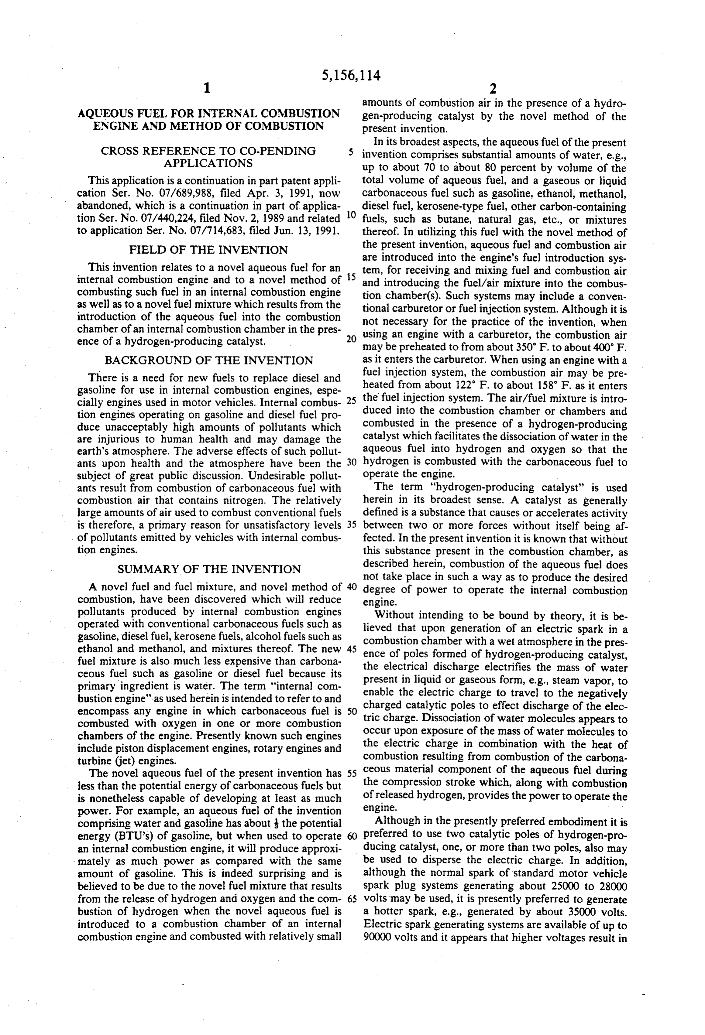
BACKGROUND OF THE INVENTION as it enters the carburetor. When using an engine with a There is a need for new fuels to replace diesel and fuel injection system, the combustion air may be pre gasoline for use in internal combustion engines, espe the heated from about 122 F. to about 158 F. as it enters fuel injection system. The air/fuel mixture is intro cially engines used in motor vehicles. Internal combus-25 duced tion engines operating on gasoline and diesel fuel pro into the combustion chamber or chambers and duce unacceptably high amounts of pollutants which combusted in the presence of a hydrogen-producing are injurious to human health and may damage the catalyst which facilitates the dissociation of water in the earth's atmosphere. The adverse effects of such pollut aqueous fuel into hydrogen and oxygen so that the ants upon health and the atmosphere have been the 30 hydrogen is combusted with the carbonaceous fuel to subject of great public discussion. Undesirable pollut operate the engine.
ants result from combustion of carbonaceous fuel with The term "hydrogen-producing catalyst” is used combustion air that contains nitrogen. The relatively herein in its broadest sense. A catalyst as generally large amounts of air used to combust conventional fuels defined is a substance that causes or accelerates activity is therefore, a primary reason for unsatisfactory levels 35 between two or more forces without itself being af. of pollutants emitted by vehicles with internal combus fected. In the present invention it is known that without tion engines. this substance present in the combustion chamber, as SUMMARY OF THE INVENTION described herein, combustion of the aqueous fuel does not take place in such a way as to produce the desired
A novel fuel and fuel mixture, and novel method of 40 degree of power to operate the internal combustion combustion, have been discovered which will reduce engine.
pollutants produced by internal combustion engines Without intending to be bound by theory, it is be operated with conventional carbonaceous fuels such as lieved that upon generation of an electric spark in a gasoline, diesel fuel, kerosene fuels, alcohol fuels such as combustion chamber with a wet atmosphere in the pres ethanol and methanol, and mixtures thereof. The new 45 ence of poles formed of hydrogen-producing catalyst, fuel mixture is also much less expensive than carbona ceous fuel such as gasoline or diesel fuel because its the electrical discharge electrifies the mass of water present in liquid or gaseous form, e.g., steam vapor, to primary ingredient is water. The term "internal com enable the electric charge to travel to the negatively bustion engine' as used herein is intended to refer to and charged catalytic poles to effect discharge of the elec encompass any engine in which carbonaceous fuel is 50 combusted with oxygen in one or more combustion tric charge. Dissociation of water molecules appears to chambers of the engine. Presently known such engines occur upon exposure of the mass of water molecules to include piston displacement engines, rotary engines and the electric charge in combination with the heat of turbine (jet) engines. combustion resulting from combustion of the carbona The novel aqueous fuel of the present invention has 55 ceous material component of the aqueous fuel during less than the potential energy of carbonaceous fuels but the compression stroke which, along with combustion is nonetheless capable of developing at least as much of released hydrogen, provides the power to operate the power. For example, an aqueous fuel of the invention engine.
comprising water and gasoline has about the potential Although in the presently preferred embodiment it is energy (BTU’s) of gasoline, but when used to operate 60 preferred to use two catalytic poles of hydrogen-pro an internal combustion engine, it will produce approxi ducing catalyst, one, or more than two poles, also may mately as much power as compared with the same be used to disperse the electric charge. In addition, amount of gasoline. This is indeed surprising and is although the normal spark of standard motor vehicle believed to be due to the novel fuel mixture that results spark plug systems generating about 25000 to 28000 from the release of hydrogen and oxygen and the com- 65 volts may be used, it is presently preferred to generate bustion of hydrogen when the novel aqueous fuel is a hotter spark, e.g., generated by about 35000 volts. introduced to a combustion chamber of an internal Electric spark generating systems are available of up to combustion engine and combusted with relatively small 90000 volts and it appears that higher voltages result in
Page 3
better dissociation of water molecules in the combustion well as excess emission of undesirable pollutants. By chamber. reducing the amount of combustion air required for DETAILED DESCRIPTION OF THE combustion in the combustion chamber, less nitrogen is PREFERRED EMBODIMENT present in the combustion chamber to combine with oxygen and form undesirable NOX pollutants emitted
As indicated previously, one of the advantages of the during engine operation. Thus, one important advan invention is that internal combustion engines may be tage of the invention is the considerable reduction in operated with novel fuels and fuel mixtures that require. NOX and other undesirable emission pollutants over significantly less combustion air for combustion of the that which are produced by conventionally operated fuel in the engine's combustion chamber. For example, O internal combustion engines using conventional carbo gasoline used as fuel for an internal combustion engine naceous fuels such as gasoline, diesel fuel, etc. in inter employing a carburetor generally requires an air to fuel nal combustion engines.
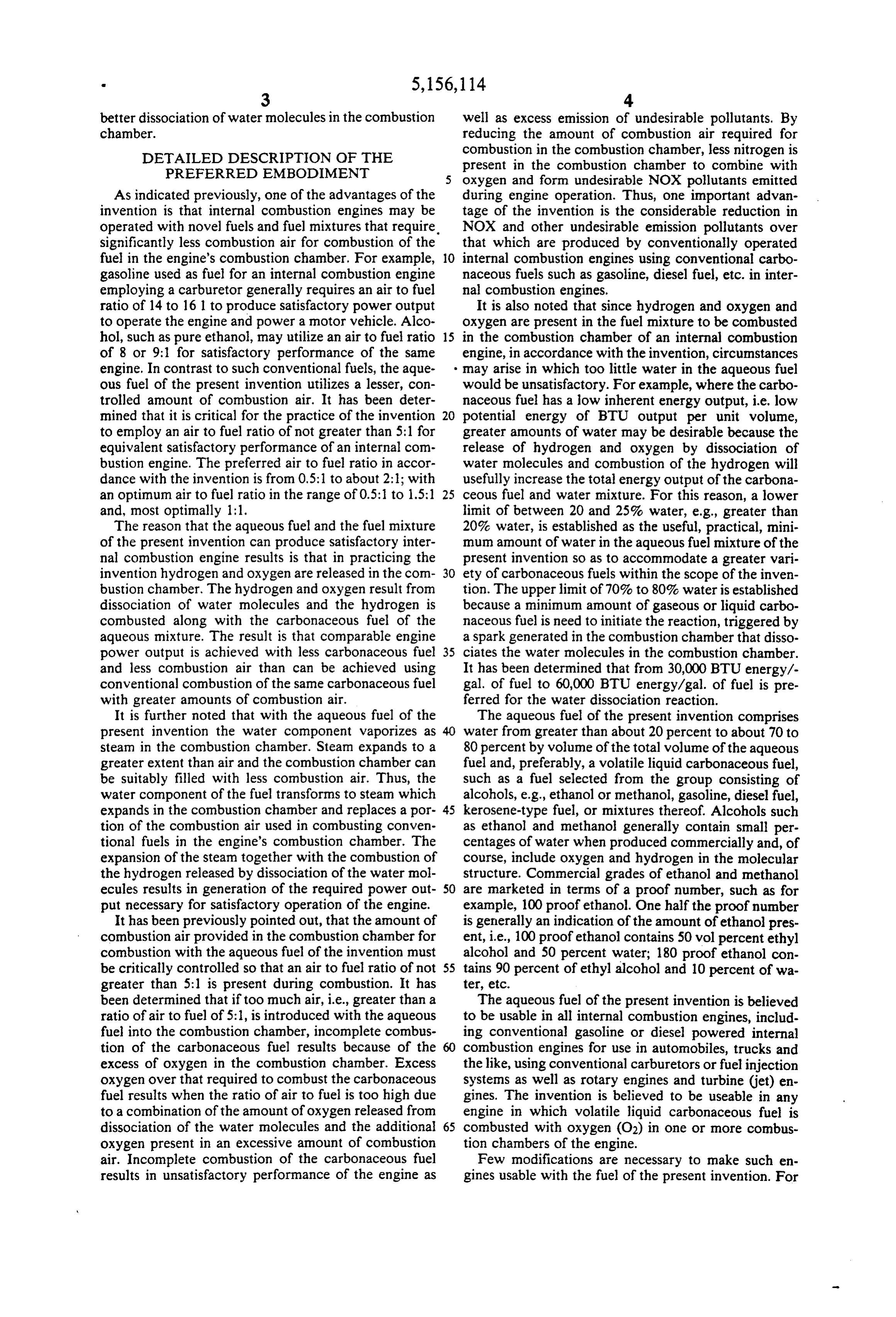
ratio of 14 to 161 to produce satisfactory power output It is also noted that since hydrogen and oxygen and to operate the engine and power a motor vehicle. Alco oxygen are present in the fuel mixture to be combusted hol, such as pure ethanol, may utilize an air to fuel ratio 15 in the combustion chamber of an internal combustion of 8 or 9:1 for satisfactory performance of the same engine, in accordance with the invention, circumstances engine. In contrast to such conventional fuels, the aque may arise in which too little water in the aqueous fuel ous fuel of the present invention utilizes a lesser, con would be unsatisfactory. For example, where the carbo trolled amount of combustion air. It has been deter naceous fuel has a low inherent energy output, i.e. low mined that it is critical for the practice of the invention 20 potential energy of BTU output per unit volume, to employ an air to fuel ratio of not greater than 5:l for greater amounts of water may be desirable because the equivalent satisfactory performance of an internal com release of hydrogen and oxygen by dissociation of bustion engine. The preferred air to fuel ratio in accor water molecules and combustion of the hydrogen will dance with the invention is from 0.5:1 to about 2:1; with usefully increase the total energy output of the carbona an optimum air to fuel ratio in the range of 0.5:1 to 1.5:1 25 ceous fuel and water mixture. For this reason, a lower and, most optimally 1:1. limit of between 20 and 25% water, e.g., greater than The reason that the aqueous fuel and the fuel mixture 20% water, is established as the useful, practical, mini of the present invention can produce satisfactory inter mum amount of water in the aqueous fuel mixture of the nal combustion engine results is that in practicing the present invention so as to accommodate a greater vari invention hydrogen and oxygen are released in the com 30 ety of carbonaceous fuels within the scope of the inven bustion chamber. The hydrogen and oxygen result from tion. The upper limit of 70% to 80% water is established dissociation of water molecules and the hydrogen is because a minimum amount of gaseous or liquid carbo combusted along with the carbonaceous fuel of the naceous fuel is need to initiate the reaction, triggered by aqueous mixture. The result is that comparable engine a spark generated in the combustion chamber that disso power output is achieved with less carbonaceous fuel 35 ciates the water molecules in the combustion chamber. and less combustion air than can be achieved using It has been determined that from 30,000 BTU energy/- conventional combustion of the same carbonaceous fuel gal. of fuel to 60,000 BTU energy/gal. of fuel is pre with greater amounts of combustion air. ferred for the water dissociation reaction. It is further noted that with the aqueous fuel of the The aqueous fuel of the present invention comprises present invention the water component vaporizes as water from greater than about 20 percent to about 70 to steam in the combustion chamber. Steam expands to a 80 percent by volume of the total volume of the aqueous greater extent than air and the combustion chamber can fuel and, preferably, a volatile liquid carbonaceous fuel, be suitably filled with less combustion air. Thus, the such as a fuel selected from the group consisting of water component of the fuel transforms to steam which alcohols, e.g., ethanol or methanol, gasoline, diesel fuel, expands in the combustion chamber and replaces a por 45 kerosene-type fuel, or mixtures thereof. Alcohols such tion of the combustion air used in combusting conven as ethanol and methanol generally contain small per tional fuels in the engine's combustion chamber. The centages of water when produced commercially and, of expansion of the steam together with the combustion of course, include oxygen and hydrogen in the molecular the hydrogen released by dissociation of the water mol structure. Commercial grades of ethanol and methanol ecules results in generation of the required power out 50 are marketed in terms of a proof number, such as for put necessary for satisfactory operation of the engine. example, 100 proof ethanol. One half the proof number It has been previously pointed out, that the amount of is generally an indication of the amount of ethanol pres combustion air provided in the combustion chamber for ent, i.e., 100 proof ethanol contains 50 vol percent ethyl combustion with the aqueous fuel of the invention must alcohol and 50 percent water; 180 proof ethanol con be critically controlled so that an air to fuel ratio of not 55 tains 90 percent of ethyl alcohol and 10 percent of wa greater than 5:1 is present during combustion. It has ter, etc.
been determined that if too much air, i.e., greater than a The aqueous fuel of the present invention is believed ratio of air to fuel of 5:1, is introduced with the aqueous to be usable in all internal combustion engines, includ fuel into the combustion chamber, incomplete combus ing conventional gasoline or diesel powered internal tion of the carbonaceous fuel results because of the combustion engines for use in automobiles, trucks and excess of oxygen in the combustion chamber. Excess the like, using conventional carburetors or fuel injection oxygen over that required to combust the carbonaceous systems as well as rotary engines and turbine (jet) en fuel results when the ratio of air to fuel is too high due gines. The invention is believed to be useable in any to a combination of the amount of oxygen released from engine in which volatile liquid carbonaceous fuel is dissociation of the water molecules and the additional 65 combusted with oxygen (O2) in one or more combus oxygen present in an excessive amount of combustion tion chambers of the engine.
air. Incomplete combustion of the carbonaceous fuel Few modifications are necessary to make such en results in unsatisfactory performance of the engine as gines usable with the fuel of the present invention. For
Page 4
example, installation of a hydrogen-producing catalyst amount of energy delivered by the fuel. It has been in the combustion chamber or chambers of the engine, observed in experiments using 100 proof alcohol as the such as described elsewhere herein, to act as a catalyst engine fuel that the engine produced the same power in the dissociation of water molecules to yield hydrogen output, i.e., watts per hour, as is produced with the same and oxygen must be made. In addition, suitable means to 5 volume of gasoline. This is indeed surprising in view of supply and control the input, quantity and flow, of the fact that the 100 proof ethanol has a theoretical combustion air and fuel to the combustion chamber(s) is energy potential of about 48,000 BTU's per gallon, with important for optimum engine operation. It is noted in a usable potential of about 35,000 to 37,500 BTU's per this regard that the air:fuel ratio is a significant factor in gallon, as compared to gasoline, which has an energy effecting combustion in the chamber(s). It is also desir 10 potential of about 123,000 BTU's per gallon, nearly able, from a practical point of view, to make the fuel three times as much. The fact that the lower BTU etha supply and fuel storage systems of rust proof materials. nol is able to generate as much power as a higher BTU A higher voltage electric spark system than generally gasoline suggests that additional power is attributable to used in internal combustion engines of motor vehicles the liberation, i.e., dissociation and combustion of hy operated with conventional carbonaceous fuels, e.g., 15 drogen and oxygen from the water. gasoline, is also preferred. Systems to provide a "hotter Inasmuch as 100 proof ethanol has been found to be a spark" are available commercially, such as from Chrys satisfactory fuel in using the method of the present ler Motor Company. As a further modification to opti invention, it is apparent that other suitable fuels may be mize use of the invention, it is desirable to employ a made by blending by use of other alcohols and by blend computer assisted electronically controlled system to 20 ing alcohols with gasoline, kerosene type fuels or diesel supply fuel to fuel injectors during the intake stroke of fuel, depending on whether the fuel is to be used in a the internal combustion engine. gasoline, turbine or diesel powered engine. Experimen The dissociation of water molecules, per se, is well tal work also indicates that 84 proof (42 percent water) known. For example, the thermo-dynamics and physi ethanol may also be used as a fuel and it is believed that cal chemistry of water/steam dissociation are described 25 aqueous fuels containing as much 70 to 80 percent water in the text entitled "Chemistry of Dissociated Water may be used.
Vapor and Related Systems" by M. Vinugopalan and THE ENGINE WITH CARBURETOR R.A. Jones, 1968, published by John Wiley & Sons, Inc.;
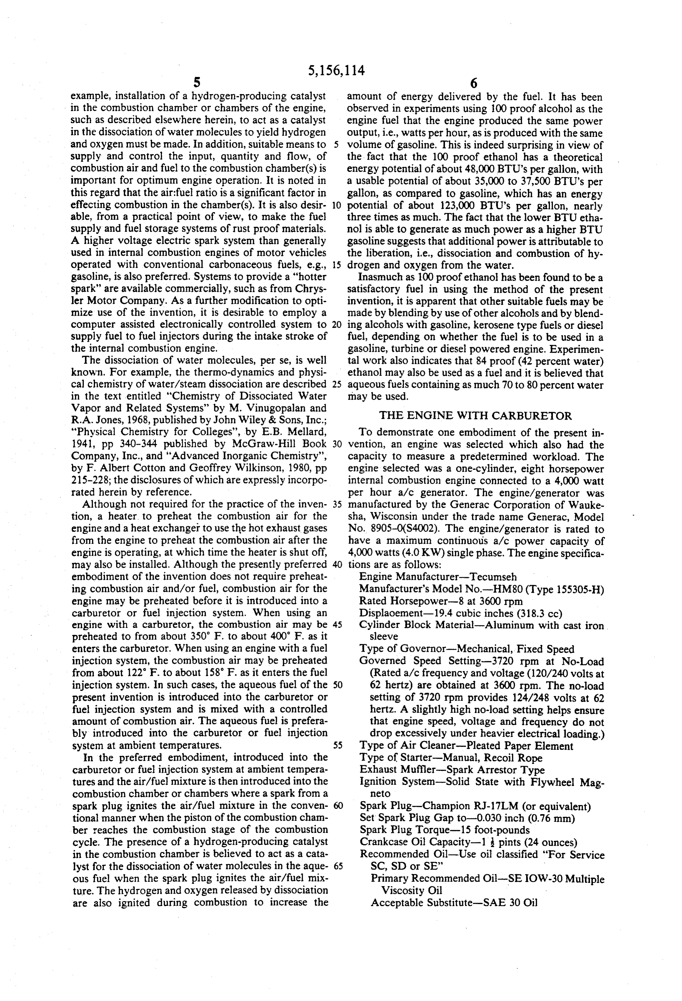
"Physical Chemistry for Colleges', by E.B. Mellard, To demonstrate one embodiment of the present in 1941, pp. 340-344 published by McGraw-Hill Book 30 vention, an engine was selected which also had the Company, Inc., and "Advanced Inorganic Chemistry", capacity to measure a predetermined workload. The by F. Albert Cotton and Geoffrey Wilkinson, 1980, pp engine selected was a one-cylinder, eight horsepower 215-228; the disclosures of which are expressly incorpo internal combustion engine connected to a 4,000 watt rated herein by reference. per hour a/c generator. The engine/generator was Although not required for the practice of the inven 35 manufactured by the Generac Corporation of Wauke tion, a heater to preheat the combustion air for the sha, Wisconsin under the trade name Generac, Model engine and a heat exchanger to use the hot exhaust gases No. 8905-0(S4002). The engine/generator is rated to from the engine to preheat the combustion air after the have a maximum continuous a/c power capacity of engine is operating, at which time the heater is shut off, 4,000 watts (4.0 KW) single phase. The engine specifica may also be installed. Although the presently preferred tions are as follows:
embodiment of the invention does not require preheat Engine Manufacturer-Tecumseh ing combustion air and/or fuel, combustion air for the Manufacturer's Model No-HM80 (Type 155305-H) engine may be preheated before it is introduced into a Rated Horsepower-8 at 3600 rpm carburetor or fuel injection system. When using an Displaoement-19.4 cubic inches (318.3 cc) engine with a carburetor, the combustion air may be AS Cylinder Block Material-Aluminum with cast iron preheated to from about 350 F. to about 400' F. as it sleeve enters the carburetor. When using an engine with a fuel Type of Governor-Mechanical, Fixed Speed injection system, the combustion air may be preheated Governed Speed Setting-3720 rpm at No-Load from about 122 F. to about 158 F. as it enters the fuel (Rated avo frequency and voltage (120/240 volts at injection system. In such cases, the aqueous fuel of the 50 62 hertz) are obtained at 3600 rpm. The no-load present invention is introduced into the carburetor or setting of 3720 rpm provides 124/248 volts at 62 fuel injection system and is mixed with a controlled hertz. A slightly high no-load setting helps ensure amount of combustion air. The aqueous fuel is prefera that engine speed, voltage and frequency do not bly introduced into the carburetor or fuel injection drop excessively under heavier electrical loading.) system at ambient temperatures. 55 Type of Air Cleaner-Pleated Paper Element In the preferred embodiment, introduced into the Type of Starter-Manual, Recoil Rope carburetor or fuel injection system at ambient tempera Exhaust Muffler-Spark Arrestor Type tures and the air/fuel mixture is then introduced into the Ignition System-Solid State with Flywheel Mag combustion chamber or chambers where a spark from a neto spark plug ignites the air/fuel mixture in the conven Spark Plug-Champion RJ-17LM (or equivalent) tional manner when the piston of the combustion cham Set Spark Plug Gap to-0.030 inch (0.76 mm) ber reaches the combustion stage of the combustion Spark Plug Torque-15 foot-pounds cycle. The presence of a hydrogen-producing catalyst Crankcase Oil Capacity-1 pints (24 ounces) in the combustion chamber is believed to act as a cata Recommended Oil-Use oil classified "For Service lyst for the dissociation of water molecules in the aque 65 SC, SD or SE' ous fuel when the spark plug ignites the air/fuel mix Primary Recommended Oil-SEIOW-30 Multiple ture. The hydrogen and oxygen released by dissociation Viscosity Oil are also ignited during combustion to increase the Acceptable Substitute-SAE 30 Oil
Page 5
Fuel Tank Capacity-1 gallon While operating the engine on 100 proof ethan . the Recommended Fuel power output on the generator was measured an indi Primary-Clean, Fresh UNLEADED Gasoline cated that the ethanol produced 36,000 watts of power Acceptable Substitute-Clean, Fresh, Leaded during a one-hour period using two liters of ethanol REGULAR Gasoline having energy potential of about 48,000 BTUs per gal A heat exchanger was installed on the engine to use lon.
the hot exhaust gases from the engine to preheat the air After the engine had stopped running on ethanol, it for combustion. A platinum bar was installed at the was operated again with the two liters of gasoline in the bottom surface of the engine head forming the top of gasoline tank. Forty seven minutes into the test, the the combustion chamber. The platinum bar weighed O engine stopped because it ran out of gasoline. Measure one ounce and measured 2-5/6 inches in length, ments taken on the generator indicated that, when the inches in width, and 1/16 inch in thickness. The plati engine was operated on gasoline, it was producing numbar was secured to the inside of the head with three power at a rate of 36,000 watts per hour for 47 minutes, stainless steel screws. using two liters of gasoline having an energy potential A second fuel tank having a capacity of two liters was 15 of about 123,000 BTUs per gallon. secured to the existing one-liter fuel tank. AT-coupling Comparing these power measurements indicates that was inserted into the existing fuel line of the motor for two liters of 100 proof ethanol produced the same communication with the fuel line for each fuel tank. A valve was inserted between the T-coupling and the fuel amount of power as two liters of gasoline. This is sur lines for each fuel tank so that either tank could be used 20 many BTUs as theassame prising inasmuch the gasoline has about 2.5 times as amount of 100 proof ethanol.
separately to feed fuel to the carburetor or to mix fuels This indicates that the extra power from the ethanol in the fuel line leading to the carburetor. must be due to the liberation and combustion of hydro TEST RUNS gen and oxygen from the relatively large amounts of water in the fuel.
A series of tests were performed to determine if 100 25 Although gasoline was used as the starter fuel to proof ethanol (50% ethanol by volume, balance water) preheat the engine and, thus, generate hot exhaust gases could be used in the motor which was modified as de scribed above, and if so, to compare the performance of the to preheat the combustion air, the use of the gasoline as the 100 proof ethanol with the same amount of gasoline. be starter fuel for preheating is not necessary and could Two liters of unleaded gasoline were poured into the 30 replaced with an electrical heat pump to preheat the second fuel tank with the valve for the second tank in combustion air until the heat exchanger can take over the closed position. Three and eight tenths liters of 100 and preheat the combustion air, whereupon the electri proof ethanol were poured into the one gallon fuel tank cal heat pump would turn off.
with the valve in the closed position. The valve for the The above tests comparing the use of the 100 proof gasoline tank was opened so that the engine could be 35 ethanol and gasoline were repeated on three subsequent occasions, each with the same results.
initially started on gasoline.
Within three minutes of starting the motor, the com A second series of tests were run which were identi bustion air entering into the carburetor was measured at cal to the above, except for the use of 84 proof ethanol 180° F. At this point, the fuel valve under the ethanol (42 percent ethyl alcohol and 58 percent water) in place tank was opened and the valve under the gasoline tank of the 100 proof ethanol. However, after running about was closed. At that point, the temperature of the air 30 seconds on the 84 proof ethanol, the engine stopped entering the carburetor had risen to 200 F. abruptly and released a fair amount of oil under high Ethanol was now the primary fuel in the motor pressure from the main bearing in the main engine. The which exhibited a certain amount of roughness during engine was restarted and abruptly stopped again after operation until the choke mechanism was adjusted by 45 operating for about 20 seconds.
reducing the air intake to the engine by approximately The above stoppage appears to have been due to 90 percent. Immediately thereafter, two, 1800 watt, preignition of the hydrogen and/or oxygen during the heat guns, having a rated heat output of 400 F, were up-stroke period of the piston which caused pressure actuated and used to heat the combustion air as it en build-up in the crank case, which in turn forced oil tered the carburetor. The temperature of the air from SO under pressure through the main bearing. The pressure the heat guns measured 390 to 395 F. inside the combustion chamber appears to have been After the engine ran on ethanol for approximately 20 relieved through the piston rings into the crank case, minutes, the heat measurement in the incoming combus and then relieved through the main bearing. tion air stabilized between 347 F. and 352 F. The The premature ignition of the hydrogen and/or oxy engine was run on the 100 proof ethanol fuel for 40 55 gen was probably caused by generating a larger amount additional minutes, for a total of one hour, until two of oxygen and hydrogen which did not occur when liters of ethanol had been used. The valve under the using 100 proof ethanol having a lesser amount of wa ethanol tank was then closed and the engine was turned te.
off by opening the choke. Eighteen hundred milliliters The preignition problem is believed to be curable by of ethanol were left remaining in the tank. using an engine having a shorter piston stroke to reduce The choke was then reset to the 90 percent closed the dwell time of the fuel, including hydrogen and oxy position, and the engine was started once again. The gen, in the combustion chamber, or by adjusting the engine responded immediately and ran as smoothly on carburetor or the electronically controlled fuel injec 100 proof ethanol as it did during the one-hour opera tion system to help reducing dwell time to avoid gener tion. 65 ating excessive amount of hydrogen and oxygen. The The engine was stopped and started in the same man engine used in the experiment had a relatively long ner on three separate occasions thereafter with the same piston stroke of 6 inches. For the conditions described results. above, the piston stroke should be no more than about 1
Page 6
inches or less to avoid the preignition problem in that After these modifications, a new series of tests were particular engine. performed using 200 proof methanol-in one of two fuel ENGINE WITH ELECTRONICALLY tanks. The engine started on the 200 proof methanol and CONTROLLED FUEL INJECTION SYSTEM the rpm setting was adjusted to 3500. The engine was allowed to run for a few minutes. During that time, the
A series of tests were run on an engine having an fuel pressure was adjusted and it was noted that 65 lbs. electronically controlled fuel injection system to deter of pressure appeared to be adequate. A thermocouple mine if that would solve the preignition problem dis was inserted close to the injector module and provided cussed above. The engine used for this purpose was a a reading of 65° C. after about 5 minutes. 3-cylinder turbo charge electronically controlled inter 10 A fuel mixture comprising 500 ml of distilled water nal combustion engine from a 1987 Chevrolet Sprint and 500 ml of 200 proof methanol were put into the which had been driven about 37,000 miles. second fuel tank this fuel and was used to operate the The head was removed from the motor block and engire. Without changing the air flow, the temperature cleaned to remove carbon deposits. Three platinum of the combustion air rose from 65 to 75 C. after about plates were attached to the inside of each head so as not 5 1 minute. The rpm reading dropped to 3100 rpm. The to interfere with valves moving inside the heads during engine ran very smoothly and was turned off and re operation. Each platinum plate was 1 centimeter in started without difficulty.
length and width and was 1/32 of an inch in thickness. The next step in the test series was to determine how Each platinum plate was attached to a head with one variations in the water content of the fuel effected en stainless steel screw through the center of each piece. 20 gine performance. Using 199 proof denatured ethanol as Carbon deposits were cleaned off each piston head and starter fuel, the engine started immediately. The fuel the engine was reassembled using new gaskets. pressure setting was reduced from 65 lbs. to 50 lbs, the The combustion air intake hose which exits from the combustion air measured 65 C., the rpm's measured turbo and leads to the injector module was divided in 3500, and the engine ran smoothly.
the middle and attached to a heat exchanger to cool the 25 The fuel was then changed into 160 proof denatured combustion air delivered to the injector. The heat ex ethanol. The fuel pressure was maintained at 50 lbs. The changer was bypassed by using two Y-junctions on combustion air temperature was measured at 67 C., the either side of the heat exchanger and by putting a but rpm's decreased to 3300, and the engine ran smoothly, terfly valve on the side closest to the turbo so that the After 10 minutes, the fuel was changed to 140 proof hot air stream could be diverted around the heat ex 30 denatured ethanol. The combustion air temperature changer and introduced directly into the injector mod rose to 70° C., the rpm's rose to 3500, and the engine ran ule. All pollution abatement equipment was removed smoothly.
from the engine but the alternator was kept in place. After 10 minutes, the fuel was changed to 120 proof The transmission was reattached to the engine because denatured ethanol. The combustion air temperature the starter mount is attached to the transmission. The 35 increased to 73°C., the rpm's decreased to 3300, and the transmission was not used during the testing. This en engine ran smoothly.
gine was inserted into a Chevrolet Sprint car having a After 10 minutes, the fuel was changed to 100 proof tailpipe and muffler system so that the engine was able denatured ethanol. The combustion air temperature to run properly. The catalytic converter was left in the increased to 74° C., the rpm's decreased to 3100, and the exhaust train but the inside of the converter was re engine ran smoothly.
moved as it was not needed. Two one-gallon plastic fuel After 10 minutes, the fuel was changed to 90 proof tanks were hooked up to the fuel pump by a T-section denatured ethanol. The combustion air temperature having manual valves so the fuel to the fuel pumped remained at 74 C., the rpm's reduced to 3100, and the could be quickly changed by opening or closing the engine ran smoothly.
valves. 45 After 10 minutes, the fuel was changed to 80 proof TEST RUNS denatured ethanol. The combustion air temperature raised to 76' C. and the rpm's reduced to 2900. At that
A series of test runs were performed to determine point, an infrequent backfire was noted in the engine. how the engine as modified above would run using a 100 proof denatured ethanol was then used as the pri variety of fuels. 50 mary fuel and the bypass to the heat exchanger was The first test utilized 200 proof methanol as a starter closed. The combustion air temperature rose to 160" C. fluid. The engine started and operated when the fuel and during the next minutes increased to 170', C. The pressure was raised to 60 to 75 lbs. When using gasoline, rpm's increased to 4000 rpm and the engine ran the fuel pressure is generally set at 3.5 to 5 lbs. smoothly.
While the engine was running on the 200 proof meth 55 Another series of tests were run with the engine ad anol, the fuel was changed to 100 proof denatured etha justed to operate at 3500 rpm's and with the heat ex nol and the motor continued operating smoothly at 3500 changer removed so that neither the fuel or combustion revolutions per minute (rpm). After about two minutes air were preheated and thus were at ambient tempera the test was stopped and the engine shut down because tures. The engine was started with 200 proof ethanol as the fuel hoses were bulging and became unsafe. These the fuel and as soon as the intake air temperature at the hoses were replaced with high pressure hoses and the injector module had risen to about 50 C., the fuel was plastic couplings and the T's were also replaced with changed to 100 proof ethanol and the engine ran copper couplings and T's. A new pressure gage was smoothly. The intake air temperature rose to 70° C. attached. During the testing, it was noted that the fuel where it stabilized. The engine was turned off, restarted mixture needed more combustion air and that the com 65 and continued to run smoothly. By adjusting and open puterized settings of the engine could not be adjusted to ing the air intake, the rpm could be increased to over provide the additional air. To overcome this, the air 4000. By slightly closing the same air intake, the rpm intake valve was opened. could be reduced to 1500. At both ranges of rpm, the
Page 7
engine ran smoothly and was turned off and restarted mixture and from 1:1 to 3:1 for the 70% water/30% without difficulty and continued to run smoothly. gasoline mixture. Normally, a gasoline engine using The rpm of an engine using the method and fuel of gasoline as fuel utilizes an air fuel ratio of 14 to 1. Such the present invention may be regulated by regulating an engine is equipped with a cylinder but is changed to the amount of air flow into the combustion chamber. In accept two inch diameter nickel bolts or screws, as the a conventional gasoline powered engine, the engine hydrogen-producing catalyst, with the screw part being rpm is regulated by regulating the amount of gasoline of inch diameter to practice the invention. The nickel that is introduced into the combustion chambers. bolts were placed inch apart on top of the piston. In It is evident that the invention involves the use of an another modification I placed a flat piece of aluminum aqueous fuel which may comprise large amounts of O (6-inches by 12-inches) inside and on top of the engine water in proportion to volatile carbonaceous fuel. A head. I drilled and tapped three inch holes into the particularly effective aqueous fuel comprises a mixture cover of the engine head in a horizontal position ap of approximately 70% water and 30% carbonaceous proximately 3 inches apart. I screwed some copper fuel. The thermal energy of the carbonaceous fuel, e.g., adapters into those holes. The adapters are connected gasoline, is reduced from the fuels high energy value, 15 with each other by a inch copper pipe which was approximately 120,000 BTU's per volume gallon in the fitted into the muffler. This device carries the exhaust case of gasoline, to a BTU content of approximately gas from the engine and I have found that it is sufficient 35,000 BTU's per volume gallon for the 70% water, to take out water vapors (steam) from the head, other 30% gasoline mixture. This BTU content of the water/- wise the water vapor will accumulate in the engine and gasoline mixture is sufficient to maintain a reaction in 20 crankcase oil, which is not desirable. the combustion chamber of an internal combustion en gine, such that the water molecule is dissociated and the tested whilethe
Each of above mentioned fuel mixtures where hydrogen molecule (H2) is separated from the oxygen the car and wereengine the found was in neutral so as not to move to be capable of self starting the molecule (O2) and the so produced hydrogen gas is engine by just turning the ignition key of the car. It was utilized as a primary power source to move the pistons not necessary to use a secondary
fuel to start the engine.
inside an internal combustion engine upon combustion. The 2.5 liter engine utilized in those tests was in a The invention is applicable with a variety of volatile standard 2.5 liter Chrysler turbo injection engine with carbonaceous fuels, including diesel oil or kerosene, and those fuels can be also mixed with up to 80% water the turbo and all smog and pollution abatement equip (e.g., diesel or kerosene) to achieve the same reaction to 30 ment removed. This engine also had a factory installed dissociate hydrogen and oxygen to release hydrogen 3-speed 1:3.09.
automatic transmission with a gear ratio of gas to power an internal combustion engine in the pres The same test series as mentioned above was also ence of a hydrogen-producing catalyst.
For this reaction to take effect, it is necessary to equip performed utilizing the same internal combustion en each combustion cavity inside the internal combustion 35 gine and car, with approximately from 20% to 25% engine with at least one, but preferably two, and maybe diesel and 75% to 80% water, with the same results. more, poles of hydrogen producing catalyst, with a Additional tests were conducted with from 20% to 25% melting point above the temperature of combustion. kerosene fuel and from 75% to 80% water where like results were also obtained.
Useful catalysts include Ni, Pt, Pt-Nialloys, Ni-stainless steel, noble metals, Re, W, and alloys thereof, which 40 In another test series, I used a 70% water/30% gaso may be utilized as a hydrogen producing catalyst in the line emulsified mixture as the only fuel to power the form of catalytic metal poles. Combustion and dissocia engine in a test "City Car", which I developed for test tion is initiated by a spark which may be created by a ing purposes. This car is a 4 door, 5 passenger front conventional electric spark generation system such as is wheel drive car with a net weight of 2,500 pounds. In used with conventional motor vehicle engines. 45 tests I was able to drive this car with the above men As a further examples of the invention, using fuel and tioned fuels from 0 to 60 miles per hour in about 6 sec combustion air at ambient temperatures I took 3 liters of onds. I tested the car to a top speed of 75 miles per hour unleaded gasoline (87 octane) with a BTU content of but the car could be driven substantially faster. about 120,000 BTU's per gallon and 7 liters of tap wa As discussed above, I have also determined that it is ter. I added 10 ml of surfactant (detergent) into this 50 important to control the air to fuel mixture to obtain mixture in a first test to enhance mixing of the water optimum results. In one test, I ran a 14:1 air fuel ratio, with the gasoline. This procedure was followed to pro the same as conventionally used with gasoline, and this duce additional mixtures with 25 ml and 40 ml of surfac resulted in an incomplete combustion within the engine tant to obtain the water/gasoline mixture. The same and large amount of water and fuel mixture exiting the procedure was also followed with using tap water 55 tail pipe. The same occurred using an air to fuel mixture which was filtered through a deionization unit and of 7:1. These tests were conducted using water and charcoal filter to remove the chlorine and other impuri gasoline at a 70% to 30% mixture, water and diesel at a ties present in the water. 75% to 25% mixture and water and kerosene at a 75% Each of the above described mixtures was then tested to 25% mixture. The incomplete combustion began to in a 4 cylinder, 2.5 liter internal combustion engine subside to satisfactory levels with air to fuel ratios of 3:1 equipped with injectors, which were attached to a fuel or less. Outer limits and optimum properties are easily rail. The fuel used during those tests was disbursed to determined for any given aqueous fuel mixture using the the fuel rail through a Bosch multi-port pressure mea procedure described above but the air to fuel ratio suring device. The engine was also equipped with a fuel should not exceed 5:1.
carburetor. The carburetor is only used for the air in 65 I have also found that a wetting agent or surfactant take into the engine as the air/fuel ratios are substan may be desirable. One such agent which has proved to tially lower and differ with the various fuels used; for be useful has a trade name of Aqua-mate2 manufactured example, starting at 0.75:1 with the 50/50 water/alcohol or distributed by Hydrotex in Dallas, Texas. Obviously,
Page 8
other wetting agents available commercially that help tures thereof, in amounts of about 30% to about 60% o disperse carbonaceous fuels in water are also usable. the total volume of said aqueous fuel. I additionally conducted tests on all three above de 6. A method according to claim 1 wherein the ratio of scribed fuels using 50% water and 50% carbonaceous air to fuel in the mixture introduced into the combustion fuel, e.g., oil based fuel, which was adequately dispersed chamber(s) is not greater than 5:1. in the water. These tests also allowed the engine to run 7. A method according to claim 1 wherein the ratio of very satisfactorily. air to fuel in the mixture introduced into the combustion Another car test is in progress using 50% water and chamber(s) is 0.75:1 to 1.5:1.
50% alcohol, with an energy content of 35,000 BTU's 8. A method according to claim 1 wherein said carbo per gallon. Test results of 20 miles per gallon of actual O naceous fuel is selected from the group consisting of driving have been achieved. With proper fuel manage ethanol, methanol or mixtures thereof. ment in the engine, efficiency can be effectively in 9. A method according to claim 1 wherein said carbo creased significantly upwards to 30 miles per gallon or naceous fuel consists essentially of gasoline. Oe. 10. A method according to claim 8 wherein the air to The benefits of the invention are substantial since 15 fuel ratio is about 1:1.
about a 70% reduction of air pollutants is obtained with 11. A method according to claim 9 wherein the air to a total elimination of NOX. There is also a 70% reduc fuel ratio is about 1:1.
tion of the fuel price to drive a vehicle through reduc 12. A method according to claim 1 wherein said com tion in the amount of gasoline used. Furthermore, there 20 bustion air is initially heated prior to introduction to the are other substantial advantages; such as possible reduc combustion chamber by a heater and then heated by tion of elimination of need for oil imports. heat from hot exhaust gases from said engine after the Other gaseous or liquid carbonaceous fuels may be engine is operating.
used, including gaseous fuels such as methane, ethane, catalyst The 13. A method according to claim 1 wherein said comprises at least one catalytic pole selected butane or natural gas and the like which could be liqui 25 from the group consisting of nickel, platinum, platinum fied and substituted for ethanol and methanol as used in the present invention, or used in gaseous form. nickel alloy, noble metals, alloys thereof, and other materials that will act as
The present invention could also be used in jet en water molecules to produce hydrogen a catalyst for the dissociation of gines, which is another form of internal combustion bustion air and said aqueous fuel are combusted when said com engine. in the 30 presence of said catalyst and an electric spark.
While the embodiments of the invention chosen herein for purposes of the disclosure are at present con lyst14.comprises
A method according to claim 1 wherein said cata at least one from the group consisting of sidered to be preferred, it is to be understood that the Ni, Pt, Pt-Ni alloys, Ni-stainless steel, noble metals, Re, invention is intended to cover all changes and modifica W, and alloys thereof.
tions of all embodiments which fall within the spirit and 35 15. A method according to claim 13 wherein said scope of the invention, wherein what is claimed is: catalyst is platinum.
1. A method for combusting an aqueous fuel in an 16. A method according to claim 13 wherein said internal combustion engine having at least one combus catalyst comprises catalytic poles of one of nickel and tion chamber, a fuel introduction system for receiving nickel containing alloys.
and mixing fuel and combustion air and introducing said 17. A method according to claim 1 wherein said fuel fuel and air mixture into said combustion chamber and an electric spark producing system for creating a spark preheated to system introduction includes a carburetor and said air is at least about 350 F. to about 400 F. as in said combustion chamber, said method comprising: said air enters said carburetor. introducing combustion air in controlled amounts 18. A method according to claim 1 wherein said fuel into said fuel introduction system, 45 introduction system includes a fuel injection system and introducing said aqueous fuel into said fuel introduc said air is preheated from 122 F. to about 158 F. as said tion system to mix with said combustion air, said air enters said fuel injection system.
fuel comprising water from about 20 percent to 19. A method according to claim 1 wherein said aque about 80 percent by volume of the total volume of ous fuel and combustion air are introduced into said fuel said fuel, and a carbonaceous fuel, and 50 introduction system at ambient temperatures. introducing and combusting said aqueous fuel and 20. A method according to claim 1 wherein the combustion air in said combustion chamber in the power output of the engine is regulated by regulating presence of a hydrogen-producing catalyst to oper the air flow into the fuel introduction system. ate said engine, said combustion being initiated by 21. A method according to claim 1 wherein said en a spark generated in said combustion chamber. 55 gine comprises an engine from the group consisting of 2. A method according to claim 1 wherein the con rotary engines, turbine engines and an engine with at bustion in the combustion chamber is initiated by a least one working cylinders in which the process of spark of at least 35000 volts. combustion takes place within the cylinders. 3. A method according to claim 1 wherein the hydro 22. A method for combusting an aqueous fuel in an gen-producing catalyst is present as at least one cata internal combustion engine having: (a) at least one com lytic pole. s bustion chamber, (b) a fuel introduction system for 4. A method according to claim 3 wherein said hy receiving and mixing fuel and combustion air and intro drogen-producing catalyst is present as a plurality of ducing said fuel and air mixture into said combustion catalytic electrically negative poles. chamber and (c) an electric spark producing system for 5. A method according to claim 1 wherein said carbo 65 creating a spark in said combustion chamber, said naceous fuel is selected from the group consisting of method comprising:
ethanol, methanol, gasoline, kerosene fuel, diesel fuel, introducing combustion air in controlled amounts other carbon-containing gaseous or liquid fuels, or mix into said fuel introduction system,
Page 9
o 5,156,114
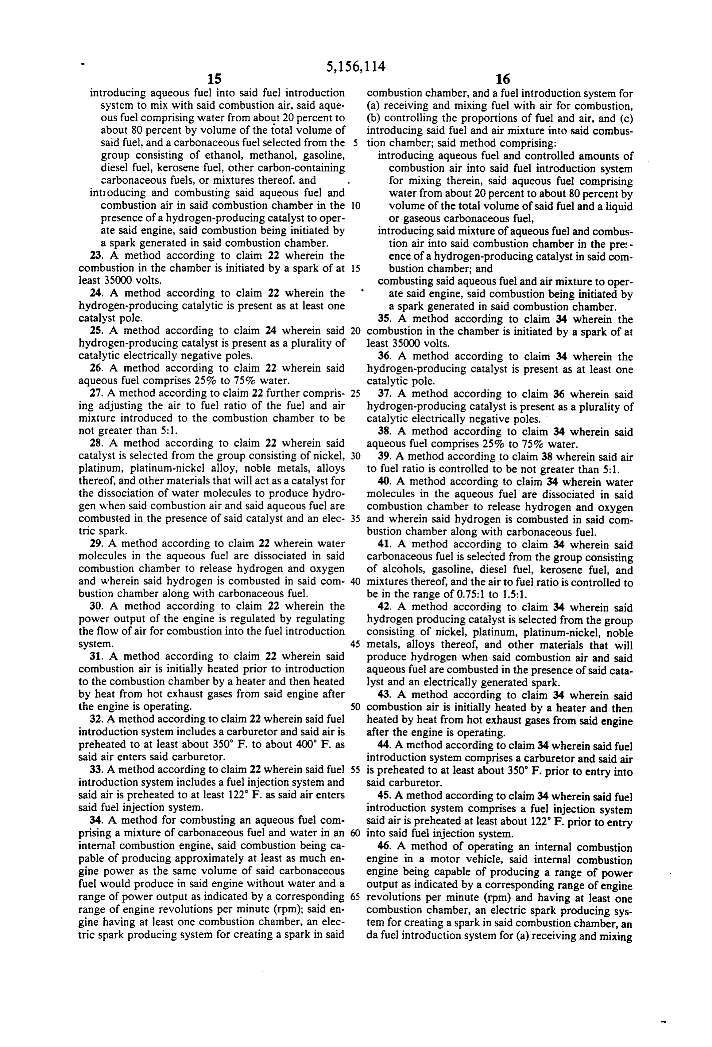
introducing aqueous fuel into said fuel introduction combustion chamber, and a fuel introduction system for system to mix with said combustion air, said aque (a) receiving and mixing fuel with air for combustion, ous fuel comprising water from about 20 percent to (b) controlling the proportions of fuel and air, and (c) about 80 percent by volume of the total volume of introducing said fuel and air mixture into said combus said fuel, and a carbonaceous fuel selected from the tion chamber; said method comprising: group consisting of ethanol, methanol, gasoline, introducing aqueous fuel and controlled amounts of diesel fuel, kerosene fuel, other carbon-containing combustion air into said fuel introduction system carbonaceous fuels, or mixtures thereof, and for mixing therein, said aqueous fuel comprising introducing and combusting said aqueous fuel and water from about 20 percent to about 80 percent by combustion air in said combustion chamber in the 10 volume of the total volume of said fuel and a liquid presence of a hydrogen-producing catalyst to oper or gaseous carbonaceous fuel, ate said engine, said combustion being initiated by introducing said mixture of aqueous fuel and combus a spark generated in said combustion chamber. tion air into said combustion chamber in the pre:- 23. A method according to claim 22 wherein the ence of a hydrogen-producing catalyst in said com combustion in the chamber is initiated by a spark of at 15 bustion chamber; and least 35000 volts. combusting said aqueous fuel and air mixture to oper 24. A method according to claim 22 wherein the ate said engine, said combustion being initiated by hydrogen-producing catalytic is present as at least one a spark generated in said combustion chamber. catalyst pole. 35. A method according to claim 34 wherein the 25. A method according to claim 24 wherein said 20 combustion in the chamber is initiated by a spark of at hydrogen-producing catalyst is present as a plurality of least 35000 volts.
catalytic electrically negative poles. 36. A method according to claim 34 wherein the 26. A method according to claim 22 wherein said hydrogen-producing catalyst is present as at least one aqueous fuel comprises 25% to 75% water. catalytic pole.
27. A method according to claim 22 further compris 25 37. A method according to claim 36 wherein said ing adjusting the air to fuel ratio of the fuel and air hydrogen-producing catalyst is present as a plurality of mixture introduced to the combustion chamber to be catalytic electrically negative poles. not greater than 5:1. 38. A method according to claim 34 wherein said 28. A method according to claim 22 wherein said aqueous fuel comprises 25% to 75% water.
catalyst is selected from the group consisting of nickel, 30 39. A method according to claim 38 wherein said air platinum, platinum-nickel alloy, noble metals, alloys to fuel ratio is controlled to be not greater than 5:1. thereof, and other materials that will act as a catalyst for 40. A method according to claim 34 wherein water the dissociation of water molecules to produce hydro molecules in the aqueous fuel are dissociated in said gen when said combustion air and said aqueous fuel are combustion chamber to release hydrogen and oxygen combusted in the presence of said catalyst and an elec 35 and wherein said hydrogen is combusted in said com tric spark. bustion chamber along with carbonaceous fuel. 29. A method according to claim 22 wherein water 41. A method according to claim 34 wherein said molecules in the aqueous fuel are dissociated in said carbonaceous fuel is selected from the group consisting combustion chamber to release hydrogen and oxygen of alcohols, gasoline, diesel fuel, kerosene fuel, and and wherein said hydrogen is combusted in said con mixtures thereof, and the air to fuel ratio is controlled to bustion chamber along with carbonaceous fuel. be in the range of 0.75:1 to 1.5:1. 30. A method according to claim 22 wherein the 42. A method according to claim 34 wherein said power output of the engine is regulated by regulating hydrogen producing catalyst is selected from the group the flow of air for combustion into the fuel introduction consisting of nickel, platinum, platinum-nickel, noble system. 45 metals, alloys thereof, and other materials that will 31. A method according to claim 22 wherein said produce hydrogen when said combustion air and said combustion air is initially heated prior to introduction aqueous fuel are combusted in the presence of said cata to the combustion chamber by a heater and then heated lyst and an electrically generated spark. by heat from hot exhaust gases from said engine after 43. A method according to claim 34 wherein said the engine is operating. SO combustion air is initially heated by a heater and then 32. A method according to claim 22 wherein said fuel heated by heat from hot exhaust gases from said engine introduction system includes a carburetor and said air is after the engine is operating.
preheated to at least about 350 F. to about 400' F. as 44. A method according to claim 34 wherein said fuel said air enters said carburetor. introduction system comprises a carburetor and said air 33. A method according to claim 22 wherein said fuel 55 is preheated to at least about 350 F. prior to entry into introduction system includes a fuel injection system and said carburetor.
said air is preheated to at least 122 F. as said air enters 45. A method according to claim 34 wherein said fuel said fuel injection system. introduction system comprises a fuel injection system 34. A method for combusting an aqueous fuel com said air is preheated at least about 122°F. prior to entry prising a mixture of carbonaceous fuel and water in an into said fuel injection system.
internal combustion engine, said combustion being ca 46. A method of operating an internal combustion pable of producing approximately at least as much en engine in a motor vehicle, said internal combustion gine power as the same volume of said carbonaceous engine being capable of producing a range of power fuel would produce in said engine without water and a output as indicated by a corresponding range of engine range of power output as indicated by a corresponding 65 revolutions per minute (rpm) and having at least one range of engine revolutions per minute (rpm); said en combustion chamber, an electric spark producing sys gine having at least one combustion chamber, an elec tem for creating a spark in said combustion chamber, an tric spark producing system for creating a spark in said dafuel introduction system for (a) receiving and mixing
Page 10
fuel with air, (b) controlling the proportions of fuel and about 80 percent by volume of the total volume of air and (c) introducing said fuel and air mixture into said said fuel, and a carbonaceous fuel, and combustion chamber, said method comprising: introducing and combusting said aqueous fuel and introducing combustion air in controlled amounts combustion air in said combustion chambers in the into said fuel introduction system, 5 presence of a hydrogen-producing catalyst to oper introducing aqueous fuel into said fuel introduction ate said engine, said combustion being initiated by system to mix with said combustion air, said aque a spark generated in said combustion chambers. ous fuel comprising water from about 20 percent to 59. A method according to claim 58 wherein the about 80 percent by volume of the total volume of combustion in the combustion chambers is initiated by a said fuel, and a liquid or gaseous carbonaceous fuel 10 spark of at least 35000 volts.
selected from the group consisting of alcohols, 60. A method according to claim 58 wherein the gasoline, diesel fuel or mixtures thereof, and hydrogen-producing catalyst is present as at least one introducing and combusting said aqueous fuel and catalytic pole.
combustion air in said combustion chamber in the 61. A method according to claim 60 wherein said presence of a hydrogen-producing catalyst to oper- 15 hydrogen-producing catalystis present as a plurality of ate said engine, said combustion being initiated by catalytic electrically negative poles. a spark generated in said combustion chamber. 62. A method according to claim 58 wherein said 47. A method according to claim 46 wherein water carbonaceous fuel is selected from the group consisting molecules in the quous fuel dissociated in said ofethanol, methanol, gasolinekerosenfeldieselfi. combustion chamber to release hydrogen and oxygen 20 other carbon-containing gaseous or liquid fuels, or mix and wherein said hydrogenis Combusted in Sidcom resthereofilamouflo 30 of bustion chamber alongR Eng. fuel. he ai the total volume of said aqueous fuel.
to fuel ratio is controlled to be not greater than 5:1.
63. A method according to claim 58 wherein the ratio of air to fuel in the mixture introduced into the combus 49. A method according to claim 47 wherein the 25 tion chambers is not greater than 5:1 amount of water in said aqueous fuel is 25% to 75% and 64. A method act to claim ss wherein the ratio it's ratio is controlled to be in the range of of air to fuel in the mixture introduced into the combus 50. A method according to claim 47 wherein said tights claim 58 wherein said hydrogen-producing catalyst comprises catalytic poles 30 b. fuel is sel f f h erein sai selected from the group consisting of nickel, platinum, Crbonacousie is selected from the group consisting platinum-nickel alloy, noble metais, alloys thereof, and of ethanol, methanol or mixtures thereof. - other materials that will act as a catalyst for dissociation 66. A method according to claim 58 wherein said of water molecules to produce hydrogen when said carbonaceous fuel consists essentially of gasoline. combustion air and said aqueous fuel are combusted in 35 method according to claim 65 wherein the air the presence of said catalyst and an electric spark. to fuel ratio is about 1:1. 51. A method according to claim 50 wherein the 68. A method according to claim 66 wherein the air combustion in the chamber is initiated by a spark of at east 35000 volts.
to A.deciding to claim 58 wherein said fuel 52. A method according to claim 50 wherein the 40 introduction system includes a carburetor. YEducing catalwtic Dole. catalyst is present as at least one in aFEER As his fuel A. Riod according to claim 52 wherein said 71. A method according to claim 58 wherein said YEpital Eisent as a plurality of EEE catalytic electically negative DOes.
A method E. to E. 1, wherein said at by heat from hot exhaust gases from said engine after least one Egling catalytic pole is present th;g E"aciding to claim 58 wherei in each combustion chamber. eel Sa
55. A method according to claim 41, wherein the air catalyst comprises at least one catalytic pole selected to fuel ratio is controlled to be about 1:1. 50 from the group consisting of nickel, platinum, platinum 56. A method according to claim 1, wherein said nickel alloy, noble metals, alloys thereof, and other aqueous fuel additionally includes a wetting agent to materials act as a catalyst for the dissociation of assist in dispersing the carbonaceous fuel in water. water molecules to produce hydrogen when said com 57. A E. i to claim 56, wherein said bustion air and said aqueous fuel are combusted in the wetting agent is a surfactant. 55 presence of said catalyst and an electric spark. 58. A method for combusting an aqueous fuel in an 73. A method according to claim 58 wherein said internal combustion engine having a plurality of com- catalyst comprises at least one from the group consist bustion chambers, a fuel introduction system for receiv- ing of Ni, Pt, Pt-Nialloys, Ni-stainless steel, noble met ing and mixing fuel and combustion air and introducing als, Re, W, and alloys thereof.
said fuel and air mixture into said combustion chambers 60 74. A method according to claim 72 wherein said and an electric spark producing system for creating a catalyst is platinum.
spark in said combustion chambers, said method com- 75. A method according to claim 72 wherein said prising: catalyst comprises catalytic poles of one of nickel and introducing combustion air in controlled amounts nickel containing alloys.
into said fuel introduction system, 65 76. A method according to claim 58 wherein said fuel introducing said aqueous fuel into said fuel introduc introduction system includes a carburetor and said air is tion system to mix with said combustion air, said preheated to at least about 350 F. to about 400 F. as fuel comprising water from about 20 percent to said air enters said carburetor.
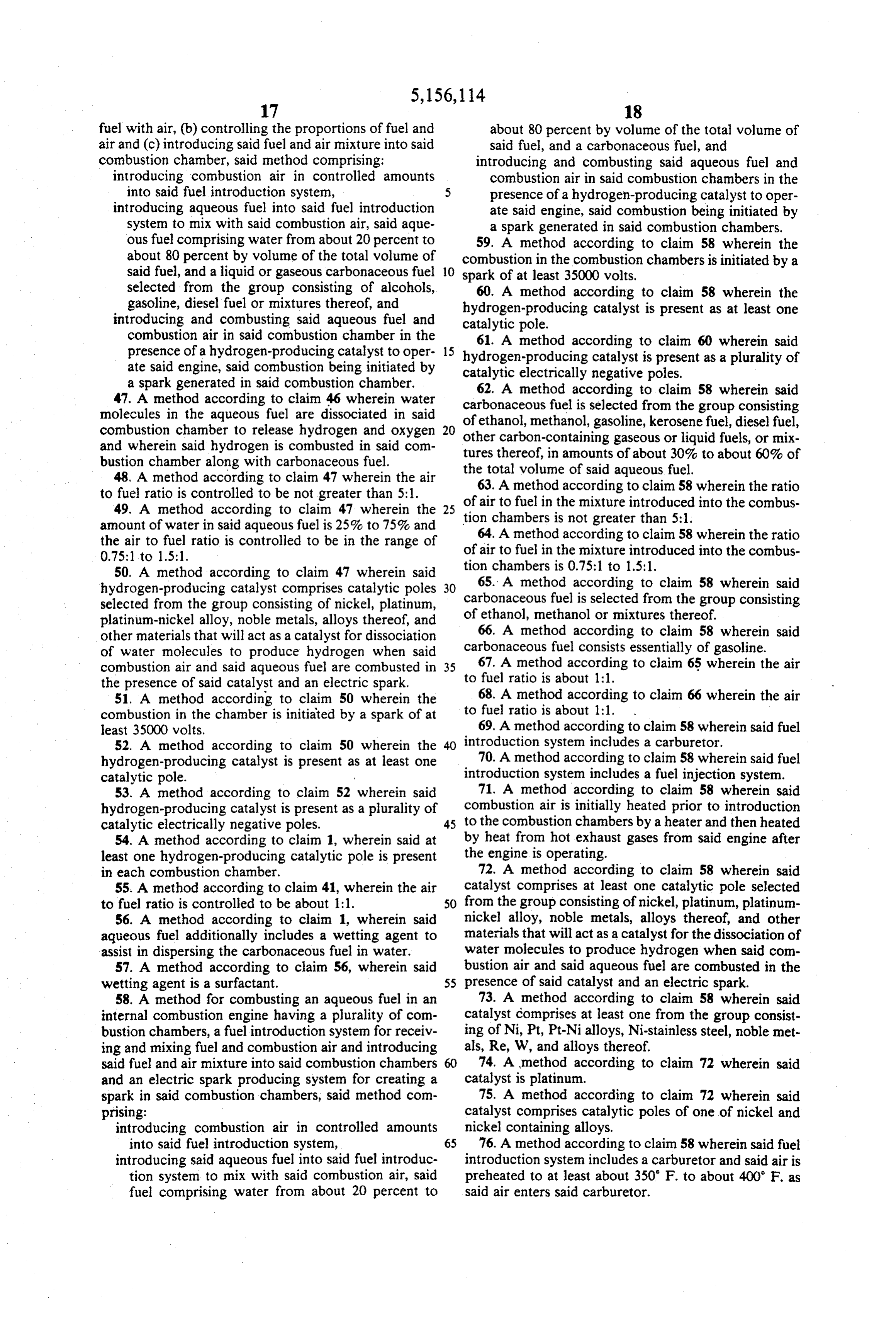
Page 11
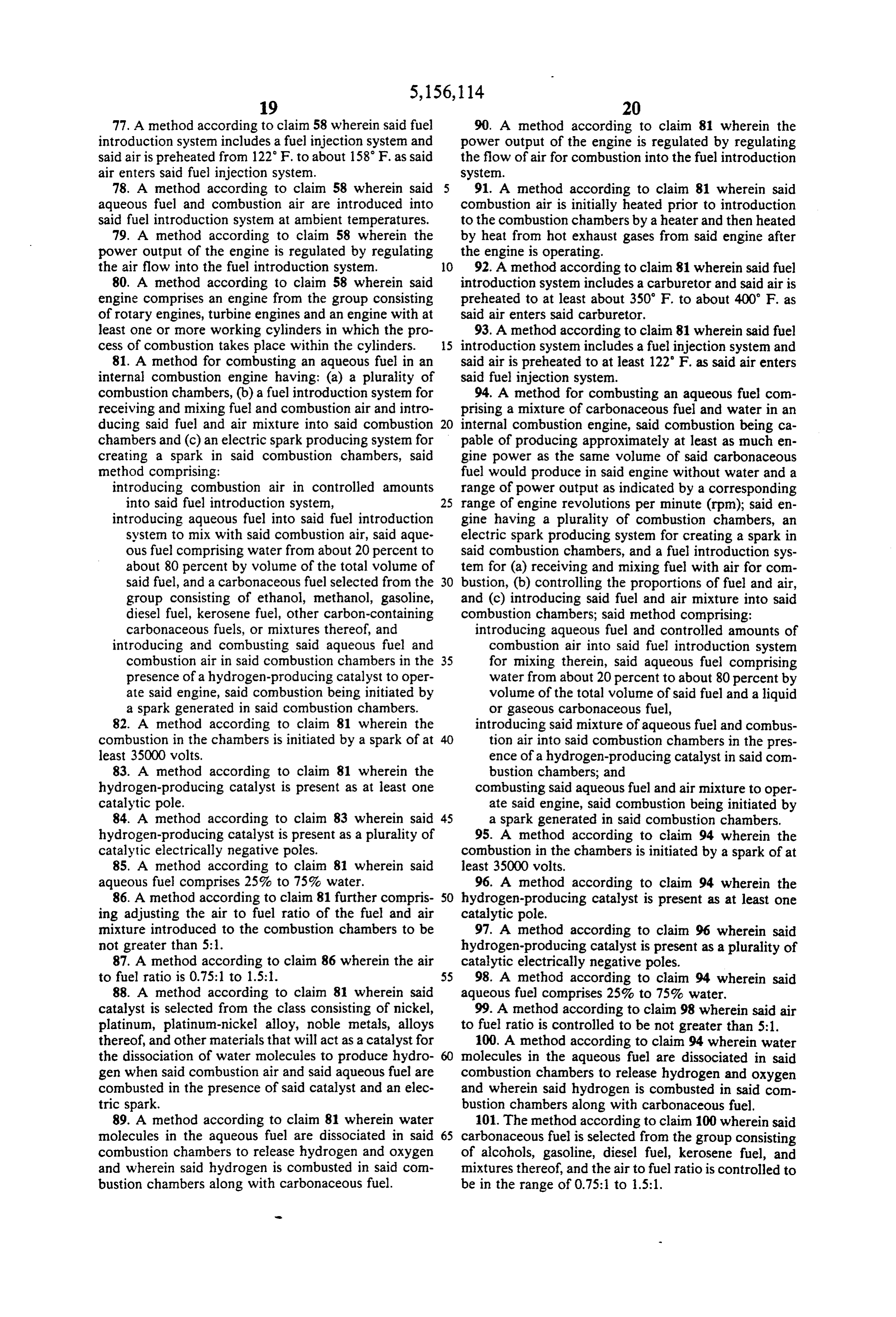
77. A method according to claim 58 wherein said fuel 90. A method according to claim 81 wherein the introduction system includes a fuel injection system and power output of the engine is regulated by regulating said air is preheated from 122 F. to about 158 F. as said the flow of air for combustion into the fuel introduction air enters said fuel injection system. system.
78. A method according to claim 58 wherein said 91. A method according to claim 81 wherein said aqueous fuel and combustion air are introduced into combustion air is initially heated prior to introduction said fuel introduction system at ambient temperatures. to the combustion chambers by a heater and then heated 79. A method according to claim 58 wherein the by heat from hot exhaust gases from said engine after power output of the engine is regulated by regulating the engine is operating.
the air flow into the fuel introduction system. 10 92. A method according to claim 81 wherein said fuel 80. A method according to claim 58 wherein said introduction system includes a carburetor and said air is engine comprises an engine from the group consisting preheated to at least about 350 F. to about 400' F. as of rotary engines, turbine engines and an engine with at said air enters said carburetor.
least one or more working cylinders in which the pro 93. A method according to claim 81 wherein said fuel cess of combustion takes place within the cylinders. 15 introduction system includes a fuel injection system and 81. A method for combusting an aqueous fuel in an said air is preheated to at least 122 F. as said air enters internal combustion engine having: (a) a plurality of said fuel injection system.
combustion chambers, (b) a fuel introduction system for 94. A method for combusting an aqueous fuel com receiving and mixing fuel and combustion air and intro prising a mixture of carbonaceous fuel and water in an ducing said fuel and air mixture into said combustion 20 internal combustion engine, said combustion being ca chambers and (c) an electric spark producing system for pable of producing approximately at least as much en creating a spark in said combustion chambers, said gine power as the same volume of said carbonaceous method comprising: fuel would produce in said engine without water and a introducing combustion air in controlled amounts range of power output as indicated by a corresponding into said fuel introduction system, 25 range of engine revolutions per minute (rpm); said en introducing aqueous fuel into said fuel introduction gine having a plurality of combustion chambers, an system to mix with said combustion air, said aque electric spark producing system for creating a spark in ous fuel comprising water from about 20 percent to said combustion chambers, and a fuel introduction sys about 80 percent by volume of the total volume of tem for (a) receiving and mixing fuel with air for com said fuel, and a carbonaceous fuel selected from the 30 bustion, (b) controlling the proportions of fuel and air, group consisting of ethanol, methanol, gasoline, and (c) introducing said fuel and air mixture into said diesel fuel, kerosene fuel, other carbon-containing combustion chambers; said method comprising: carbonaceous fuels, or mixtures thereof, and introducing aqueous fuel and controlled amounts of introducing and combusting said aqueous fuel and combustion air into said fuel introduction system combustion air in said combustion chambers in the 35 for mixing therein, said aqueous fuel comprising presence of a hydrogen-producing catalyst to oper water from about 20 percent to about 80 percent by ate said engine, said combustion being initiated by volume of the total volume of said fuel and a liquid a spark generated in said combustion chambers. or gaseous carbonaceous fuel, 82. A method according to claim 81 wherein the introducing said mixture of aqueous fuel and combus combustion in the chambers is initiated by a spark of at tion air into said combustion chambers in the pres least 35000 volts. ence of a hydrogen-producing catalyst in said com 83. A method according to claim 81 wherein the bustion chambers; and hydrogen-producing catalyst is present as at least one combusting said aqueous fuel and air mixture to oper catalytic pole. ate said engine, said combustion being initiated by 84. A method according to claim 83 wherein said 45 a spark generated in said combustion chambers. hydrogen-producing catalyst is present as a plurality of 95. A method according to claim 94 wherein the catalytic electrically negative poles. combustion in the chambers is initiated by a spark of at 85. A method according to claim 81 wherein said least 35000 volts.
aqueous fuel comprises 25% to 75% water. 96. A method according to claim 94 wherein the 86. A method according to claim 81 further compris 50 hydrogen-producing catalyst is present as at least one ing adjusting the air to fuel ratio of the fuel and air catalytic pole.
mixture introduced to the combustion chambers to be 97. A method according to claim 96 wherein said not greater than 5:1. hydrogen-producing catalyst is present as a plurality of 87. A method according to claim 86 wherein the air catalytic electrically negative poles.
to fuel ratio is 0.75:1 to 1.5:1. 55 98. A method according to claim 94 wherein said 88. A method according to claim 81 wherein said aqueous fuel comprises 25% to 75% water.
catalyst is selected from the class consisting of nickel, 99. A method according to claim 98 wherein said air platinum, platinum-nickel alloy, noble metals, alloys to fuel ratio is controlled to be not greater than 5:1. thereof, and other materials that will act as a catalyst for 100. A method according to claim 94 wherein water the dissociation of water molecules to produce hydro molecules in the aqueous fuel are dissociated in said gen when said combustion air and said aqueous fuel are combustion chambers to release hydrogen and oxygen combusted in the presence of said catalyst and an elec and wherein said hydrogen is combusted in said com tric spark. bustion chambers along with carbonaceous fuel. 89. A method according to claim 81 wherein water 101. The method according to claim 100 wherein said molecules in the aqueous fuel are dissociated in said 65 carbonaceous fuel is selected from the group consisting combustion chambers to release hydrogen and oxygen of alcohols, gasoline, diesel fuel, kerosene fuel, and and wherein said hydrogen is combusted in said con mixtures thereof, and the air to fuel ratio is controlled to bustion chambers along with carbonaceous fuel. be in the range of 0.75:1 to 1.5:1.
Page 12
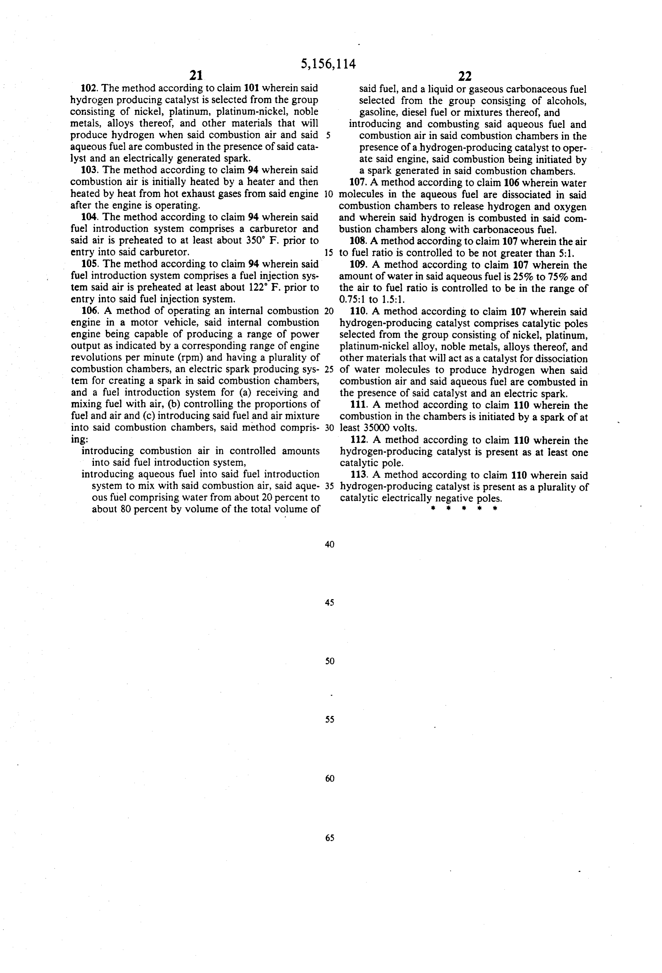
102. The method according to claim 101 wherein said said fuel, and a liquid or gaseous carbonaceous fuel hydrogen producing catalyst is selected from the group selected from the group consisting of alcohols, consisting of nickel, platinum, platinum-nickel, noble gasoline, diesel fuel or mixtures thereof, and metals, alloys thereof, and other materials that will introducing and combusting said aqueous fuel and produce hydrogen when said combustion air and said 5 combustion air in said combustion chambers in the aqueous fuel are combusted in the presence of said cata presence of a hydrogen-producing catalyst to oper lyst and an electrically generated spark. ate said engine, said combustion being initiated by 103. The method according to claim 94 wherein said a spark generated in said combustion chambers. combustion air is initially heated by a heater and then 107. A method according to claim 106 wherein water heated by heat from hot exhaust gases from said engine O molecules in the aqueous fuel are dissociated in said after the engine is operating. combustion chambers to release hydrogen and oxygen 104. The method according to claim 94 wherein said and wherein said hydrogen is combusted in said com fuel introduction system comprises a carburetor and bustion chambers along with carbonaceous fuel. said air is preheated to at least about 350 F. prior to 108. A method according to claim 107 wherein the air entry into said carburetor. 15 to fuel ratio is controlled to be not greater than 5:1. 105. The method according to claim 94 wherein said 109. A method according to claim 107 wherein the fuel introduction system comprises a fuel injection sys amount of water in said aqueous fuel is 25% to 75% and tem said air is preheated at least about 122 F. prior to the air to fuel ratio is controlled to be in the range of entry into said fuel injection system, 0.75:1 to 1.5:1.
106. A method of operating an internal combustion 20 110. A method according to claim 107 wherein said engine in a motor vehicle, said internal combustion hydrogen-producing catalyst comprises catalytic poles engine being capable of producing a range of power selected from the group consisting of nickel, platinum, output as indicated by a corresponding range of engine platinum-nickel alloy, noble metals, alloys thereof, and revolutions per minute (rpm) and having a plurality of other materials that will act as a catalyst for dissociation combustion chambers, an electric spark producing sys 25 of water molecules to produce hydrogen when said ten for creating a spark in said combustion chambers, combustion air and said aqueous fuel are combusted in and a fuel introduction system for (a) receiving and the presence of said catalyst and an electric spark. mixing fuel with air, (b) controlling the proportions of 111. A method according to claim 110 wherein the fuel and air and (c) introducing said fuel and air mixture combustion in the chambers is initiated by a spark of at into said combustion chambers, said method compris 30 least 35000 volts.
1ng: 112. A method according to claim 110 wherein the introducing combustion air in controlled amounts hydrogen-producing catalyst is present as at least one into said fuel introduction system, catalytic pole.
introducing aqueous fuel into said fuel introduction 113. A method according to claim 110 wherein said system to mix with said combustion air, said aque 35 hydrogen-producing catalyst is present as a plurality of ous fuel comprising water from about 20 percent to catalytic electrically negative poles.
about 80 percent by volume of the total volume of ak Ek k xx x
Provenance
- Collection
- Cited prior art
- Original PDF
- patentimages.storage.googleapis.com →
- Filed
- 1991-05-03
- Pages
- 12
- Method
- pdftotext (the PDF's own text layer) + pdftoppm 300dpi page scans
- Source
- Google Patents bibliographic record
- Granted
- 1992-10-20
- Inventors
- Rudolf W. Gunnerman
- Transcribed from
- patentimages.storage.googleapis.com →