patent · US4099489
Fuel regenerated non-polluting internal combustion engine
11 July 1978
Page 1 — bibliographic record
United States Patent (19) 11) 4,099,489 Bradley (45) Jul. 11, 1978 (54) FUEL REGENERATED NON-POLLUTING 2,633,707 4/1953 Hermitte et al. ................ 60/39.18 B INTERNAL COMBUSTON ENGINE 3,311,097 3/1967 Mittelstaedt ..... ... 123/DIG. 12 3,362,883 1/1968 Wright .......... ... 123/DIG. 12 76) Inventor: Curtis E. Bradley, 4517 Calle 3,459,953 8/1969 Hughes et al. ... 123/DIG. 12 Ventura, Phoenix, Ariz. 85018 3,653,364 4/1972 Bogan ...................................... 123/3 3,696,795. 10/1972 Smith ....... ... 123/119 E (21) Appl. No.: 744,193 3,704,587 12/1972 Krieb et al. ... 60/39.18 B 3,792,690 2/1974 Cooper .................................... 123/3
Primary Examiner-Charles J. Myhre
Related U.S. Application Data Assistant Examiner-David D. Reynolds 60 Continuation-in-part of Ser. No. 620,021, Oct. 6, 1975, 57 ABSTRACT
No. 4,003,344, and Ser. No. 620,023, Oct. 6, 1975, Pat. An internal combustion engine in which heat is derived No. 4,003,345, each is a division of Ser. No. 456,974, from the engine cooling system and the exhaust to heat Aug. 1, 1974, Pat. No. 3,939,806. a working fluid and to transform it into a gas which (51) Int. Cl? ....................... F02B 43/08; F01K 23/10 drives a turbine which operates a generator. Direct (52) U.S. C. .................................... 123/3; 123/119 E; current from the latter is delivered to an electrolysis cell 123/DIG. 12; 60/618 containing purified water which is decomposed into (58) Field of Search ............... 123/1 A, 3, 41.2, 41.21, hydrogen and oxygen. The oxygen is injected under 123/119 E, 121, DIG. 12; 60/39.18 B, 616, 618 pressure into the combustion chambers of the engine References Cited while the hydrogen is also injected under pressure into (56) a carburetor where it is combined with conventional
1966,345 7/1934 Harrell ................................. 123/121 2,509,498 9/1950 Heyl ............................. 123/DIG. 12 11 Claims, 6 Drawing Figures
Page 2
Drawing sheet — no readable text.
Page 3
Drawing sheet — no readable text.
Page 4
Drawing sheet — no readable text.
Page 5
Drawing sheet — no readable text.
Page 6
Thus, air pollution is reduced or avoided to a large
FUEL REGENERATED NON-POLLUTING extent and energy is conserved.
INTERNAL COMBUSTON ENGINE OBJECTS OF THE INVENTION
This application is a continuation-in-part of the co pending applications of Curtis E. Bradley, Ser. Nos. 5 With the foregoing conditions in mind, the present 620,021 now U.S. Pat. No. 4,003,204, 620,022 now U.S. invention has in view the following objectives: Pat. No. 4,003,344 and 620,023 now U.S. Pat. No. 1. To provide an internal combustion engine includ 4,003,345, all filed Oct. 6, 1975 and entitled: FUEL ing means for deriving heat from the engine, utilizing REGENERATED and NON-POLLUTING COM this heat to generate an electric current, decomposing BUSTION ENGINE, and which applications are divi- 10 water by passing the electric current therethrough to sions of the application of the said Curtis E. Bradley, provide hydrogen, and then using the hydrogen as a Ser. No. 456,974 filed Aug. 1, 1974 and issued as U.S. fuel in the engine.
Pat. No. 3,939,806. 2. To provide, in an internal combustion engine of the The present invention relates to internal combustion type noted, a circulatory system for a working fluid in engines and is concerned primarily with the generation the form of water and gas therefrom and which includes of power derived from engine heat to produce an elec means for heating the working fluid either from the tric current which decomposes water to provide hydro engine cooling system and/or the engine exhaust. gen which is used as fuel for the engine. 3. To provide, in an internal combustion engine of the BACKGROUND OF THE INVENTION character aforesaid, a turbine which is driven by the 20 working fluid as it is expanded into gases. This turbine
At the present time, the public is confronted with two generator system may be of the type commonly known basic problems related to the consumption of fuel in an as a Rankine Cycle.
internal combustion engine. One of these problems is 4. To provide, in an internal combustion engine of the the pollution of the ambient atmosphere by the products kind described, a generator which is driven by the tur of combustion. These noxious products are oxides of 25 bine and which generates a DC current which is con nitrogen (NO), carbon monoxide (CO) and unburned ducted to an electrolysis cell.
hydrocarbons (HC). Of late, considerable attention has 5. To provide, in conjunction with an internal com been devoted in attempt to minimize if not completely bustion engine of the type noted, a water supply tank obviate these noxious products of combustion. 30 from which water is passed to the electrolysis cell. The other problem deals with the conservation of 6. To provide, in conjunction with an internal com fuel. The country is now faced with an energy shortage bustion engine of the character aforesaid, a hydrogen and much effort has been directed to the broad object of tank into which hydrogen is introduced from the elec regenerating fuel from the heat of the engine, with the trolysis cell under pressure.
regenerated fuel being passed back to the engine for is 7. To provide, in an internal combustion engine of the consumption therein. type described, a conduit which conducts hydrogen It is now a well recognized phenomenum that when under pressure from the electrolysis cell and/or the hydrogen is used as a fuel in an internal combustion hydrogen tank to a hydrogen carburetor. engine the noxious products of combustion which pol 8. To provide, in an internal combustion engine of the lute the atmosphere are reduced to a high degree if not 40 type noted, a conduit for passing oxygen under pressure completely eliminated. This has been found to be true from the electrolysis cell to the combustion chambers of not only when the hydrogen is the only fuel used, but the engine.
also when the hydrogen is combined with conventional 9. To provide, in an internal combustion engine of the hydrocarbon fuels such as gasoline, diesel oil and the character aforesaid, a fuel pump for conducting hybro like. 45 carbon fuel from a fuel tank to a carburetor, a pump for The decomposition of water into its components of the working fluid system, and a pump for delivering oxygen and hydrogen by passing an electric current water from the water tank and through the working therethrough is also a now well recognized phenome fluid system to the electrolysis cell.
num. Other methods of decomposing water to provide 10. To provide, in an internal combustion engine of oxygen have also been proposed. One of these is to pass 50 the kind described, an AC current generator which is water or steam into contact with heated ferrous balls. part of the Rankine Cycle engine together with a power Moreover, it has been proposed to use hydrogen so conditioner including a rectifier, a transformer and a generated as a fuel in internal combustion engines. voltage regulator for converting the AC current to DC However, from the apparent lack of public acceptance current of a required voltage which is delivered to the of such technology, it is believed that this failure is due 55 electolysis cell.
to the highly inefficient nature of such processes. 11. To provide, in an internal combustion engine of In the above identified applications and patent the the type noted, a battery which is charged by DC cur oxygen from an electrolysis cell is either exhausted to rent from the rectifier.
ambient atmosphere or combined with air at the air 12. To provide, in an internal combustion engine of intake of the engine. This is not the most efficient use of 60 the character aforesaid, a second generator which is the oxygen which is possible. Also, there is some loss of powered by the momentum of a vehicle in which the heat in the working fluid circulatory system after the engine is installed being slowed by braking and which gases pass through the turbine and before these gases delivers AC current to the power conditioner. are delivered to a condenser. Various other more detailed objects and advantages The present invention is founded on the basic concept 65 of the invention, such as arise in connection with carry of utilizing heat derived from an internal combustion ing out the above ideas in a practical embodiment will, engine to generate electric power which decomposes in part, become apparent and, in part, be hereafter water to provide hydrogen which is used in the engine. stated as the description of the invention proceeds.
Page 7
SUMMARY OF THE INVENTION erator, electrolysis cell, fuel supply tank, water supply tank, hydrogen tank and pumps therefor are the same as
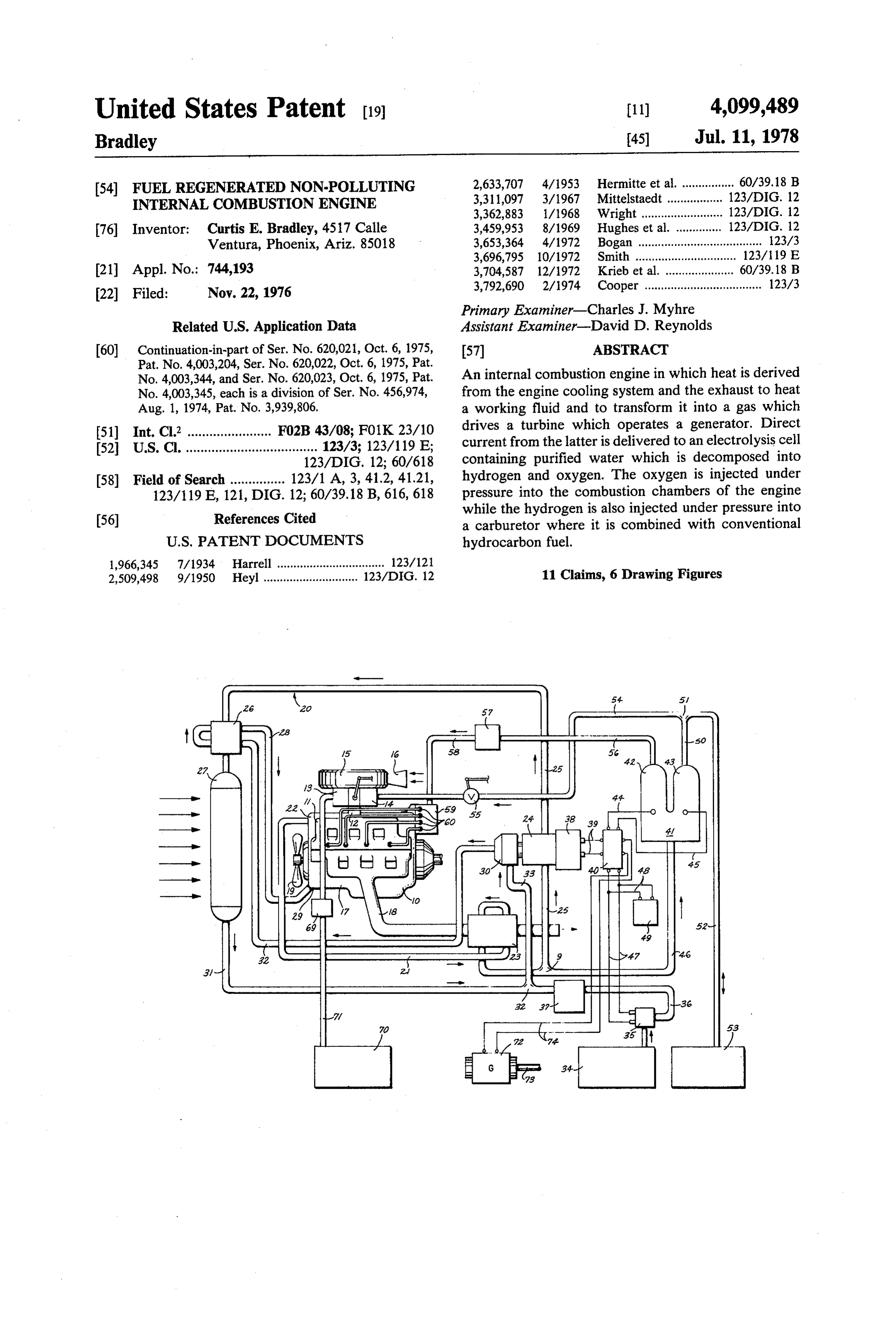
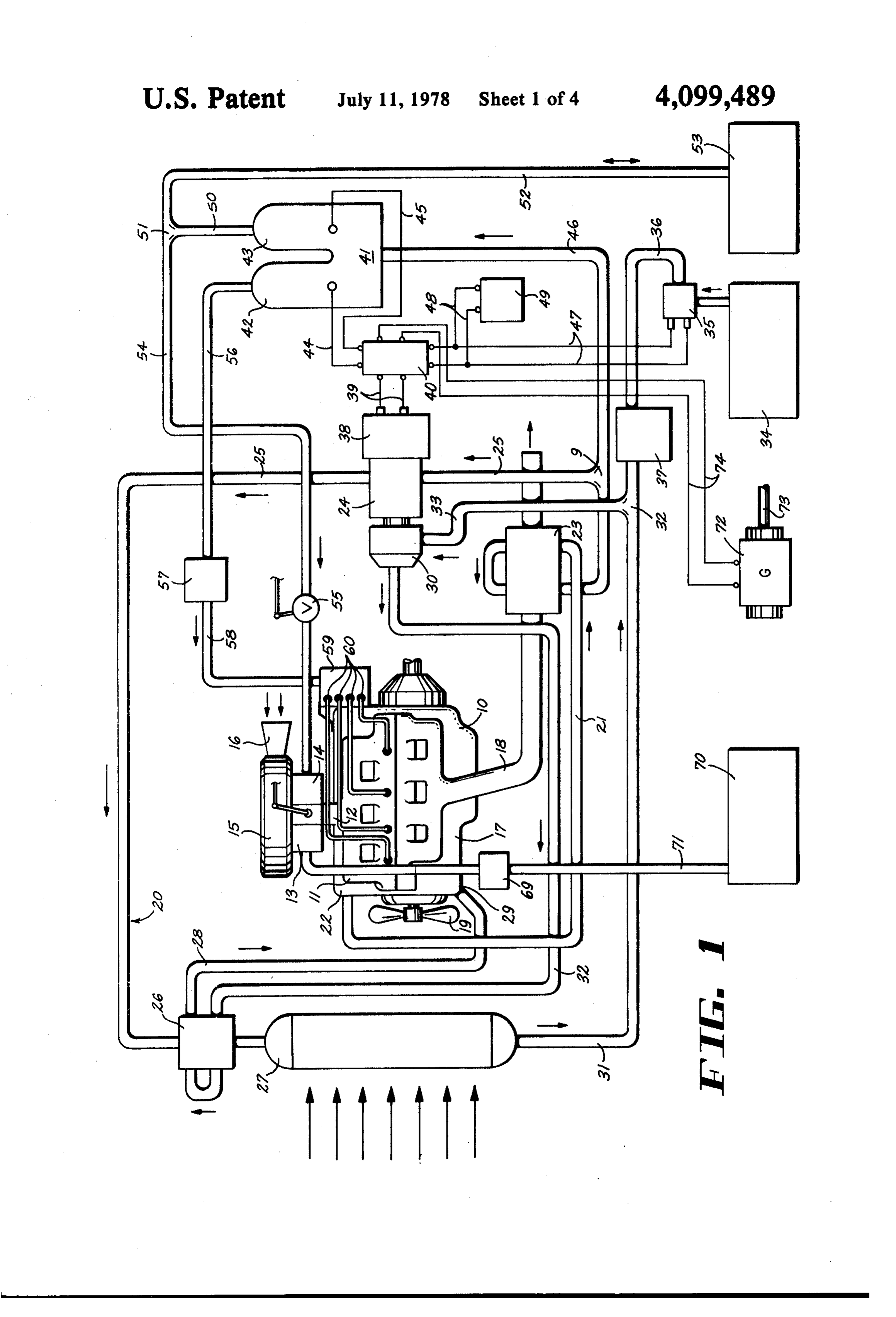
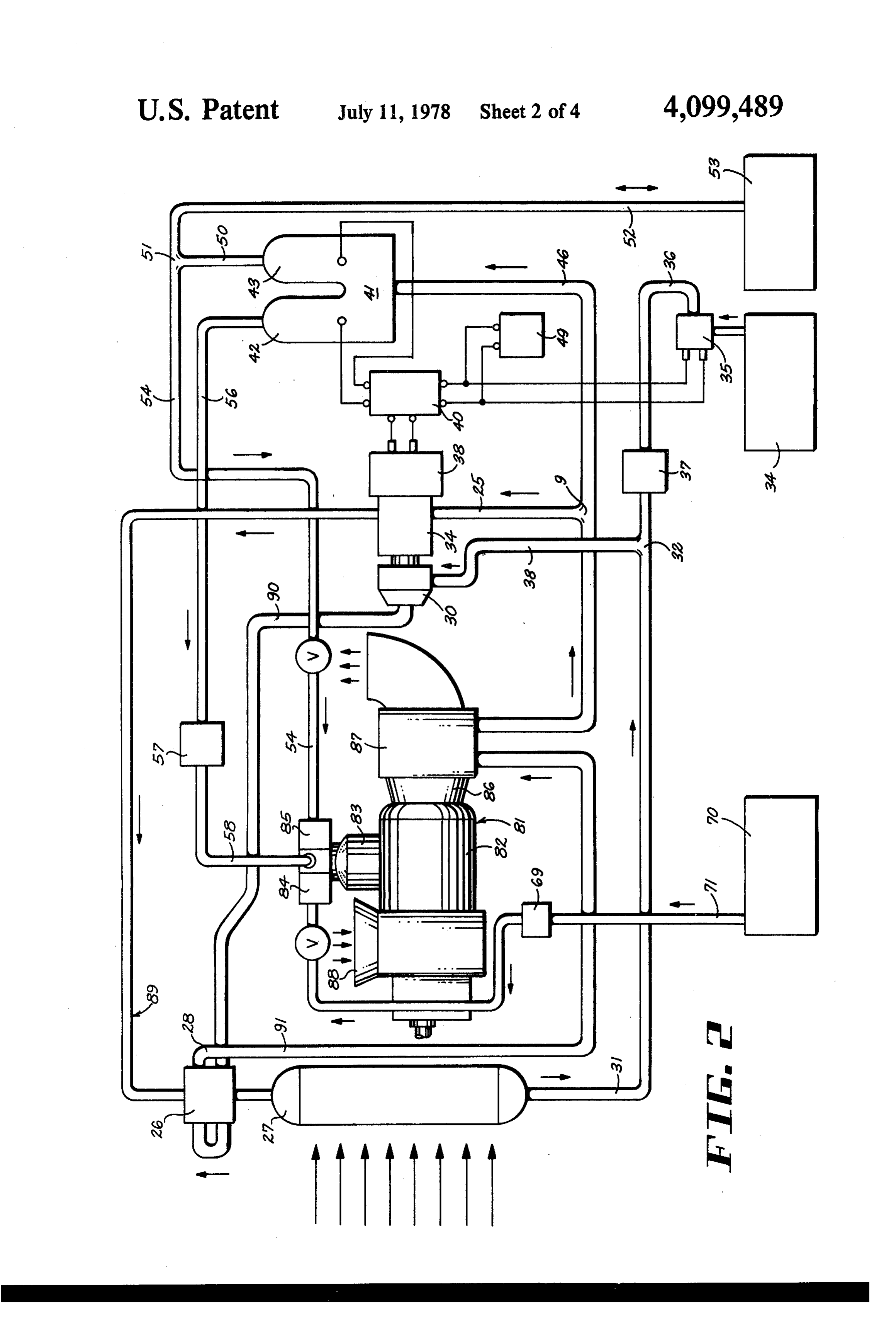
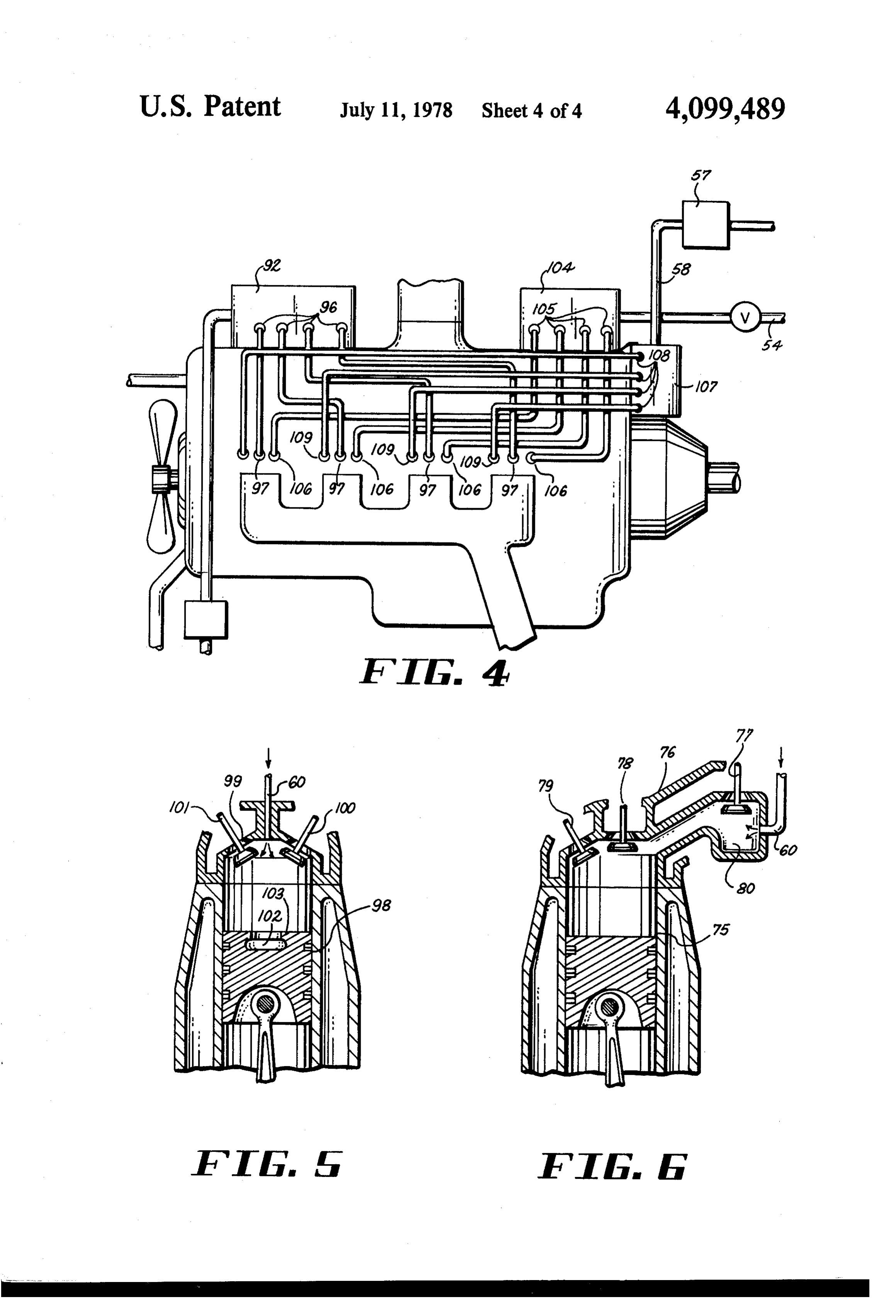
The foregoing objects are achieved by providing an described in the preceding paragraphs. The difference internal combustion engine which includes a cooling between this embodiment of the invention and the oth system, a fuel intake manifold and an exhaust manifold ers resides in the construction of the turbine engine. having an exhaust pipe extending therefrom, with a For a full and more complete understanding of the circulatory system which derives heat from the cooling invention, reference may be had to the following de system and the exhaust pipe for a working fluid which scription and the accompanying drawings, wherein: is water. A turbine in a Rankine Cycle is included in the FIG. 1 is a diagrammatic view illustrating the essen working fluid system and is operated by the gases de 10 tial elements of the present invention as applied to a rived from heating the working fluid. The working fluid conventional internal combustion engine of the piston system is closed and also include a condenser for con type in which the fuel is ignited by spark plugs; verting the gaseous working fluid back to its liquid form FIG. 2 is a diagrammatic view depicting the inven and a pump for circulating the working fluid. A heat tion as applied to a turbine engine; exchanger is associated with the working fluid system 15 FIG. 3 is another diagrammatic view of the invention immediately in advance of the condenser to derive heat as incorporated into a diesel engine; from the gases after they have passed through the tur FIG. 4 is a schematic view of a modification of the bine. diesel engine embodiment;
The pump which circulates the water draws water FIG. 5 is a section through a portion of a cylinder of from a water supply tank and a portion of this water is 20 a diesel engine and a piston therein, and drawn from and delivered to an electrolysis cell. An FIG. 6 is a similar section through a portion of a AC generator is driven by the turbine and the AC cur cylinder and piston of an Otto engine. rent therefrom is conditioned by a power conditioner which delivers DC current to the electrolysis cell and FIRST EMBODIMENT battery. A second generator delivers AC current to the 25 Referring now to the drawings wherein like refer condition and is driven by the momentum of the vehicle ence characters denote corresponding elements on which it is installed and is slowed down as by brak throughout the several views, and first more particu ing. larly to FIG. 1, an internal combustion engine of the Mounted on top of the engine in accordance with Otto or piston type in which the fuel is ignited by spark conventional practice is an air filter, and immediately 30 plugs is shown as including an engine block represented below this air filter are two carburetors which commu at 10. Mounted on engine block 10 is a fuel intake mani nicate with the intake manifold of the engine. One of fold 11 having a main stem 12 on which is mounted a these carburetors is for conventional hydrocarbon fuel carburetor or injector 13 for hydrocarbon fuel such as and the other is for hydrogen. The hydrocarbon fuel is gasoline, and a hydrogen carburetor or injector 14. conducted from a supply tank therefor to the carburetor 35 Both of the carburetors 13 and 14 communicate with for hydrocarbon fuel through a conduit including a stem 12. Mounted above carburetors 13 and 14 is an air pump. Another conduit extends from the other carbure filter 15 having an air intake 16.
tor which is for hydrogen to that portion of the electrol Carried by engine block 10 is an exhaust manifold 17 ysis cell in which hydrogen is collected. The hydrogen from which extends an exhaust pipe 18. Engine block10 is under high pressure created by two sources. One of 40 includes a cooling system in accordance with accepted these is the heat of the circulating system and electroly practice and hence, is notherein illustrated. However, a sis and the other is the pump which circulates the water. fan which may be considered as a part of the cooling A portion of the hydrogen is conducted to a tank and system is indicated at 19.
the remainder is passed through a conduit to a hydrogen A closed circulatory system as in a Rankine Cycle carburetor. A valve is included in the conduit and is 45 having working fluid such as water and gas derived operable to determine when hydrogen is to be delivered therefrom is designated generally at 20. It comprises a to the hydrogen carburetor. conduit 21 which is in heat conducted relation to the Oxygen under pressure is injected into the combus cooling system of the engine to the point indicated at 22. tion chambers of the engine where it is mixed with It extends to and passes through to a heat exchanger 23 combustive fuel from the manifold. 50 which is disposed about an exhaust pipe. From heat Now known internal combustion engines may be exchanger 23 conduit 21 extends to a junction 9 from catalogued into three types. One is the conventional which a tube 25 extends to a turbine 24. Otto cycle internal combustion engine now widely used The heat exchanger 23 converts the water into a in which the fuel is ignited by spark plugs. The second gaseous state which drives the turbine. After leaving is the well known diesel cycle engine in which the fuel 55 the turbine, these gases pass through a conduit 25, is ignited by compression of the intaken air gases. The through a second heat exchanger 26 and to a condenser third is the Brayton cycle turbine type internal combus 27.
tion engine in which the fuel is burned at constant pres A pipe 28 passes through heat exchanger 26 and is sure to drive a turbine rather than a piston. The present connected to the engine cooling system at 29. The other invention is susceptible of embodiment in the internal leg of the pipe 28 communicates with a pump 30 which combustion engines of each of the above noted types. is driven by turbine 24.
The invention as applied to the first type is summarized Connected to the lower end of condenser 27 is an in the preceding paragraphs. The apparatus required for other pipe 31 which extends to a junction 32 and from a diesel engine is substantially the same, with the nota ble exception that the carburetor for the hydrocarbon 65 theAlatter a tube 33 extends to pump 30. water supply tank is designated at 34 and water is fuel and the fuel intake manifold are replaced by fuel drawn therefrom by pump 35 through a tube 36 to injectors. In the case of the turbine engine, the working junction point 32 with a water purifier 37 being in fluid circulatory system, turbine included therein, gen cluded in tube 36.
Page 8
At this point it is well to note that water from the SECOND EMBODIMENT condenser and purified water from the supply tank 34 This embodiment diagrammatically illustrates the intermix at junction point 32 and the combined waters.
are circulated by pumps 30 and 35. incorporation of the present invention into an internal Turbine 24 drives an AC generator 38 that is con combustion FIG. 2. The engine of the turbine type as illustrated in turbine engine is represented at 81. It in nected by lines 39 to a power conditioner 40 which includes a rectifier, a transformer and a voltage regula cludes a casing 82 providing a combustion chamber into tor to convert the AC current to DC current of a re which fuel is introduced through an intake 83. A meter ing control 84 for hydrocarbon fuel is mounted over quired voltage. An electrolysis cell 41 incldes a leg 42 in 10 intake which oxygen is collected and a leg 43 for hydrogen. exhaust83pipe as is a metering control 85 for hydrogen. An Electrolysis cell 41 is connected to conditioner 40 by thereabout is a86heat extends from casing 82 and disposed lines 44 and 45. Water under pressure is delivered to cell the heat exchanger exchanger
87, which corresponds to 1. An air intake for en 41 by a pipe 46 which extends from junction 9 to cell 41. gine 81 is represented at 88. The remaining elements It is evident that the water is decomposed in the cell and 15 illustrated in FIG. 2, with some exceptions, the oxygen and hydrogen gases collected in the respec as the corresponding elements of FIG. 1, andarehave the same been tive legs 42 and 43 are under a high pressure due to the so designated by like reference characters. heat and the action of pump 30. The working fluid system is somewhat different from From conditioner 40 lines 47 extend to a motor (not that of FIG. 1 and is designated at 89. It comprises a illustrated) which drives pump 35. Lines 48 are takken 20 conduit 90 which extends from pump 30 and passes off of lines 47 and charge a battery 49. through heat exchanger 26 from which it emerges as A conduit 50 extends from the upper end of hydrogen conduit 91 which passes around exhaust pipe 86 in heat leg 43 to a junction 51. From the latter a pipe 52 goes to exchanger 87. From the latter it extends to junction 9 a hydrogen storage tank 53. From the other side of from which tube 25 goes to turbine 24 and conduit 46 to junction 51 a tube 54 which includes a valve 55 goes to 25 cell 41.
hydrogen carburetor 14. From oxygen leg 42 a conduit The main difference between the apparatus of FIG. 1 56 extends to an oxygen tank 57 and from the latter, and that of FIG. 2 is that in the water circulating system another conduit 58 goes to an oxygen distributor 59 that of FIG. 2, heat is derived from heat exchangers 26 and is mounted on engine block 10. From distributor 59 87 alone and not from the cooling system of the engine. tubes 60 extend to intake manifold 11. A tank for hydro 30 Also, conduit 58 from oxygen tank 57 discharges into carbon fuel such as gasoline is shown at 70 and from it fuel intake 83.
a conduit 71 extends to carburetor 13 for hydrocarbon The operation of the turbine is substantially the same fuel with a pump 69 being included at conduit 71. as that described above in connection with FIG. 1 with Generator 72 is mounted at an appropriate point on the notable exception that the fuel pump indicated at 72 the vehicle on which the engine is installed and includes 35 includes a fuel metering control governing the rate at a drive shaft 73 which is driven by one of the driving or which fuel is delivered from fuel tank 70 to the fuel traction elements of the vehicle under the momentum metering control 84. Also, hydrogen gas is delivered by derived from the slowing down of the vehicle as by conduit 54 to fuel metering control 85.
braking. AC current from the generator 72 is conducted THIRD EMBODIMENT by lines 74 to rectifier 40. This is illustrated in FIG. 3 and shows the invention OPERATION-FIRST EMBODIMENT as applied to a diesel engine. The difference between the It is believed that the description of the various ele diesel engine of FIG. 3 and the conventional Otto en ments of FIG. 1 set forth renders it unnecessary to 45 gine fold of FIG. 1 resides in the elimination of intake mani 11 and carburetor 13 which are replaced by fuel herein set forth a detailed description thereof. How injectors.
ever, it is noted that the water which goes to electroly block 93 Thus, and manifold 92 is mounted on the engine receives diesel fuel from fuel injector sis cell 41 is purified. Moreover, this water, is heated pump and distribution supply tank 94 through tube 95. from three sources, one of these is the cooling system of Distribution tubes 96 extend from manifold 92 to injec the engine and the other two are the heat exchangers 23 50 tion ports 97 in engine block 93. Just and 26. As the water is heated electrolysis cell 41 is also duit 58 delivers oxygen under pressureastoin aFIG. 1 con distributor heated and the pressure of the gases therein is increased 59. From the latter, tubes 60 extend to the combustion by this heat and is also under the pressure of pump 30 chambers of the diesel engine. which is slightly enhanced by pump 35. Thus, the hy drogen is injected under pressure into the hydrogen 55 sure providesFIG.
Just as in 1 the injection of oxygen under pres for a stratified mixture of the oxygen with carburetor and the oxygen is also injected under pres the carbureted fuel, a cylinder of a diesel engine is sure to the fuel intake manifold. shown in FIG. 5 at 98 and includes a head 99 in which Upon reference to FIG. 6, the advantage to be gained are mounted valves 100 and 101. Tubes 60 enter the by injecting the oxygen under pressure becomes appar head centrally thereof and from which oxygen is in ent. The cylinder of an internal combustion engine of 60 jected into chamber 102 formed in piston 103. the Otto type is shown at 75. It includes a head 76 in FOURTHEMBODIMENT which are mounted fuel intake valves 77 and 78 and an exhaust valve 79. Head 76 includes a chamber 80 imme Referring more particularly to FIG. 4, a modification diately below valve 77 and into which a tube 60 opens. of the diesel engine embodiment is therein illustrated in This arrangement provides what is known in the art as 65 which hydrogen gas is delivered directly to the injec a stratified combustion of the fuel. Thus, the oxygen is tion ports in the engine block rather than to the air first intake. Conduit 54 is connected to a hydrogen fuel in mixed with the rich fuel and then with the leaner . jector fuel mixtures. pump and distribution manifold 104 from which
Page 9
extend four distribution tubes 105 which are connected power conditioner including a rectifier, a transformer at their other ends to injection ports 106. and a voltage regulator for converting said AC current Just as in FIG. 3 diesel fuel distributor 92 is mounted on block 93 and tubes 96 extend therefrom to injection to to
DC current of a required voltage which is delivered said electrolysis cell.
ports 97. 5
Oxygen distributor 107 receives oxygen under pres water is drawn 5. The internal combustion engine of claim 4 in which sure from tank 57 through tube 58. From distributor 107 duit connected tofrom said water tank through said con four tubes 108 extend to injection ports 109. The same driven pump includedworking said in said fluid system by a motor last mentioned conduit;
stratified mixture action takes place as described above and electric lines between said motor and said power in FIG. 5.
10 conditioner.
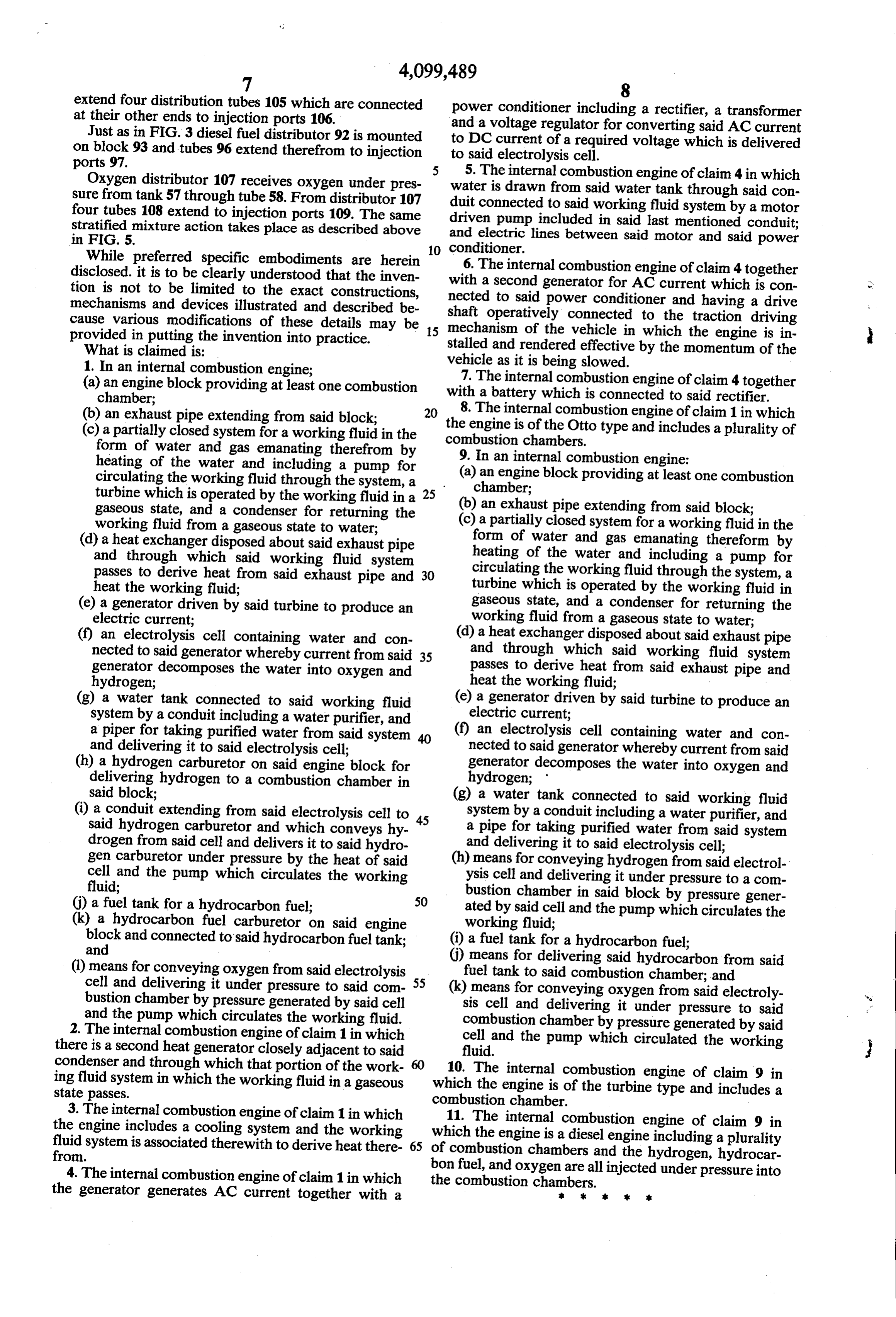
While preferred specific embodiments are herein 6. The internal combustion engine of claim 4 together disclosed. it is to be clearly understood that the inven with tion is not to be limited to the exact constructions, necteda second generator for AC current which is con to said power conditioner and having a drive mechanisms and devices illustrated and described be cause various modifications of these details may be 15 shaft operatively connected to the traction driving mechanism of the vehicle in which the engine is in provided in putting the invention into practice. stalled and rendered effective by the momentum of the What is claimed is:
1. In an internal combustion engine; vehicle as it is being slowed. (a) an engine block providing at least one combustion with 7. The internal combustion engine of claim 4 together chamber; a battery which is connected to said rectifier. (b) an exhaust pipe extending from said block; 20 8. The internal combustion engine of claim 1 in which the engine is of the Otto type and includes a plurality of (c) a partially closed system for a working fluid in the combustion form of water and gas emanating therefrom by chambers.
heating of the water and including a pump for 9. In an internal combustion engine: circulating the working fluid through the system, a (a) an engine block providing at least one combustion turbine which is operated by the working fluid in a 25 (b)chamber; an exhaust pipe extending from said block; gaseous state, and a condenser for returning the (c) a partially closed system for a working fluid in the working fluid from a gaseous state to water;
(d) a heat exchanger disposed about said exhaust pipe form of water and gas emanating thereform by and through which said working fluid system heating of the water and including a pump for passes to derive heat from said exhaust pipe and 30 circulating the working fluid through the system, a heat the working fluid; turbine which is operated by the working fluid in (e) a generator driven by said turbine to produce an gaseous state, and a condenser for returning the electric current; working fluid from a gaseous state to water; (f) an electrolysis cell containing water and con (d) a heat exchanger disposed about said exhaust pipe nected to said generator whereby current from said 35 and through which said working fluid system generator decomposes the water into oxygen and passes to derive heat from said exhaust pipe and hydrogen; heat the working fluid;
(g) a water tank connected to said working fluid (e) a generator driven by said turbine to produce an system by a conduit including a water purifier, and electric current;
a piper for taking purified water from said system (f) an electrolysis cell containing water and con and delivering it to said electrolysis cell; nected to said generator whereby current from said (h) a hydrogen carburetor on said engine block for generator decomposes the water into oxygen and delivering hydrogen to a combustion chamber in hydrogen;
said block; (g) a water tank connected to said working fluid (i) a conduit extending from said electrolysis cell to 45 system by a conduit including a water purifier, and said hydrogen carburetor and which conveys hy a pipe for taking purified water from said system drogen from said cell and delivers it to said hydro and delivering it to said electrolysis cell; gen carburetor under pressure by the heat of said (h) means for conveying hydrogen from said electrol cell and the pump which circulates the working ysis cell and delivering it under pressure to a com fluid; bustion chamber in said block by pressure gener (j) a fuel tank for a hydrocarbon fuel; 50 ated by said cell and the pump which circulates the (k) a hydrocarbon fuel carburetor on said engine working fluid;
block and and connected to said hydrocarbon fuel tank; (i) a fuel tank for a hydrocarbon fuel; () means for delivering said hydrocarbon from said (l) means for conveying oxygen from said electrolysis cell and delivering it under pressure to said com 55 (k)fuel means tank to said combustion chamber; and for conveying oxygen from said electroly bustion chamber by pressure generated by said cell sis cell and delivering it under pressure to said and the pump which circulates the working fluid. combustion chamber by pressure generated by said 2. The internal combustion engine of claim 1 in which cell and the pump which circulated the working there is a second heat generator closely adjacent to said fluid.
condenser and through which that portion of the work 10. The internal combustion engine of claim 9 in ing fluid system in which the working fluid in a gaseous which the engine is of the turbine type and includes a state passes. combustion chamber.
3. The internal combustion engine of claim 1 in which 11. The internal combustion engine of claim 9 in the engine includes a cooling system and the working which the engine is a diesel engine including a plurality fluid system is associated therewith to derive heat there 65 of combustion from. chambers and the hydrogen, hydrocar bon fuel, 4. The internal combustion engine of claim 1 in which the combustion chambers. and oxygen are all injected under pressure into the generator generates AC current together with a k k k
Provenance
- Collection
- Cited prior art
- Original PDF
- patentimages.storage.googleapis.com →
- Filed
- 1976-11-22
- Pages
- 9
- Method
- pdftotext (the PDF's own text layer) + pdftoppm 300dpi page scans
- Source
- Google Patents bibliographic record
- Granted
- 1978-07-11
- Inventors
- Curtis E. Bradley
- Transcribed from
- patentimages.storage.googleapis.com →