patent · US4368696
Electrolytic supplemental fuel generation for motor vehicles
18 January 1983
Page 1 — bibliographic record
United States Patent (19) 11 4,368,696 Reinhardt 45) Jan. 18, 1983 54 ELECTROLYTICSUPPLEMENTAL FUEL Primary Examiner-William A. Cuchlinski, Jr. GENERATION FOR MOTOR VEHICLES Attorney, Agent, or Firm-Harvey B. Jacobson 76) Inventor: Weldon E. Reinhardt, 121 19 De 57 ABSTRACT Moya Dr., SE., Fort Myers, Fla. A combination internal combustion engine and electro
lyzer for producing hydrogen and oxygen gases from (21) Appl. No.: 173,900 water on board a motor vehicle in order to supplement (22 Filed: Jul. 29, 1980 the gasoline fuel for the engine further includes a heat activated engine such as a Stirling engine to provide the 51 Int. Cl. .............................................. FO2B 43/10 electrical current necessary to decompose the water, 52 U.S. C. ....................................... 123/3; 123/1 A; the Stirling engine being activated directly from heat 123/DIG. 12; 60/616 derived from the exhaust of the internal combustion 58) Field of Search .............. 123/1 A, 2, 3, DIG. 12; engine. The oxygen and hydrogen gases formed by the 60/616, 618, 517; 204/284, DIG. 4 electrolysis of water are passed to the air intake of the (56) References Cited carburetor of the internal combustion engine and enable
the use of a much leaner gasoline to air mixture to run the engine thus increasing gas mileage and reducing air 3,939,806 2/1976 Bradley ................................... 123/3 pollutants formed by the internal combustion engine. 4,070,860 1/1978 Hanson ............................. 60/517 X 4,271,793 6/1981 Valdespino ............................. 123/3 8 Claims, 7 Drawing Figures
Page 2
Drawing sheet — no readable text.
Page 3
Drawing sheet — no readable text.
Page 4
Drawing sheet — no readable text.
Page 5
ELECTROLYTIC SUPPLEMENTAL FUEL SUMMARY OF THE INVENTION GENERATION FOR MOTOR VEHICLES The present invention produces supplemental oxygen
BACKGROUND OF THE INVENTION
and hydrogen gas fuel on board a motor vehicle in order to supplement the gasoline fuel used by the inter
Field of the Invention. nal combustion engine. The supplemental fuel is pro duced
At the present time, the fuel economy of an automo molecule by the electrolysis of water, separating the water bile is increasing in importance for consumer accep introducing into its hydrogen and oxygen components by tance, and for many consumers is the primary reason for 10 generation ofanelectric electrical current therethrough. The purchasing a given automobile. Of course, the rising ing a heat activated current is accomplished by utiliz cost of gasoline is the reason for needed increased fuel piston linear alternator engine orasany engine such the Stirling free other engine economy, though other factors such as reduced pollu tion due to greater fuel combustion and even national which derives its energy from the waste heat of the interest in conserving fuel as a broad measure to reduce 15 exhaust of the internal combustion engine. The inven oil imports and thus bolster our own economy and tion is characterized by the heat activated engine deriv ing its energy from direct heat exchange with the ex national security are other factors for the need of fuel haust gases enabling the device to be installed in any
The present invention provides for an internal com existing automobile, unlike prior art devices developed bustion engine having increased fuel efficiency in which 20 to provide a hydrogen-rich fuel mixture requiring elab heat derived from the exhaust gases of the internal com orate and bulky pipe systems and complex electrical bustion engine is used to generate an electric current generating equipment to decompose the water into its which decomposes water into separate hydrogen and component gases.it is an object of the present invention oxygen gases which are used to supplement the hydro to Accordingly, produce hydrogen and oxygen gas on board a motor carbon fuel used by the engine. The generation of the 25 vehicle in order to supplement gasoline as a fuel for an electric current is made possible by an engine activated by the direct exchange of heat from the exhaust gases of internal combustion engine.
It is a further object of the invention to produce hy the internal combustion engine. The supplemental oxy drogen gen and hydrogen reduces the amount of hydrocarbon order toand oxygen gas on board a motor vehicle in supplement gasoline as a fuel for an internal fuel needed to provide combustion thus increasing fuel 30 combustion engine by generating an electric current for economy and reducing air pollution to a large extent. decomposing water into its gaseous components, in 2. Disclosure Statement
Lately, considerable effort has been directed to the which the electric current is generated by a heat acti vated linear alternator engine deriving its energy from broad object of conserving fuel during operation of a 35 the waste heat of the exhaust. motor vehicle. Such efforts include changes in the de It is another object of the present invention to pro sign of internal combustion engines, changes in the duce hydrogen and oxygen gas on board a motor vehi aerodynamics of the automobile body itself, substituting light metal or plastic materials for heavier automobile cle in order to supplement gasoline as a fuel for an inter components, and even changing the fuel itself, such as nal combustion engine by the aforesaid method, in utilizing gasohol and increased use of diesel cycle en which the heat activated linear alternator engine de gines. rives its energy by direct heat exchange with the ex Modification to the workings of the internal combus haust gases from the internal combustion engine. tion engine include regenerating fuel from the exhaust It is still another object of the present invention to of the engine, with the regenerated fuel being passed 45 provide a device for decomposing water into its gaseous back to the engine for consumption therein. A modified components in order to supplement gasoline as a fuel for internal combustion engine similar to the present inven internal combustion engines, in which the device in tion is disclosed in U.S. Pat. Nos. 3,939,806; 4,003,344; cludes a heat activated linear alternator engine to gener and 4,099,489, issued to Bradley and which disclose ate an electric current, which current is utilized to de supplementing the fuel used to power an internal com 50 compose the water, and including means to feed the bustion engine by adding hydrogen and oxygen gases formed gaseous products to the carburetor of the inter formed by the electrolysis of water to a system of carbu nal combustion engine.
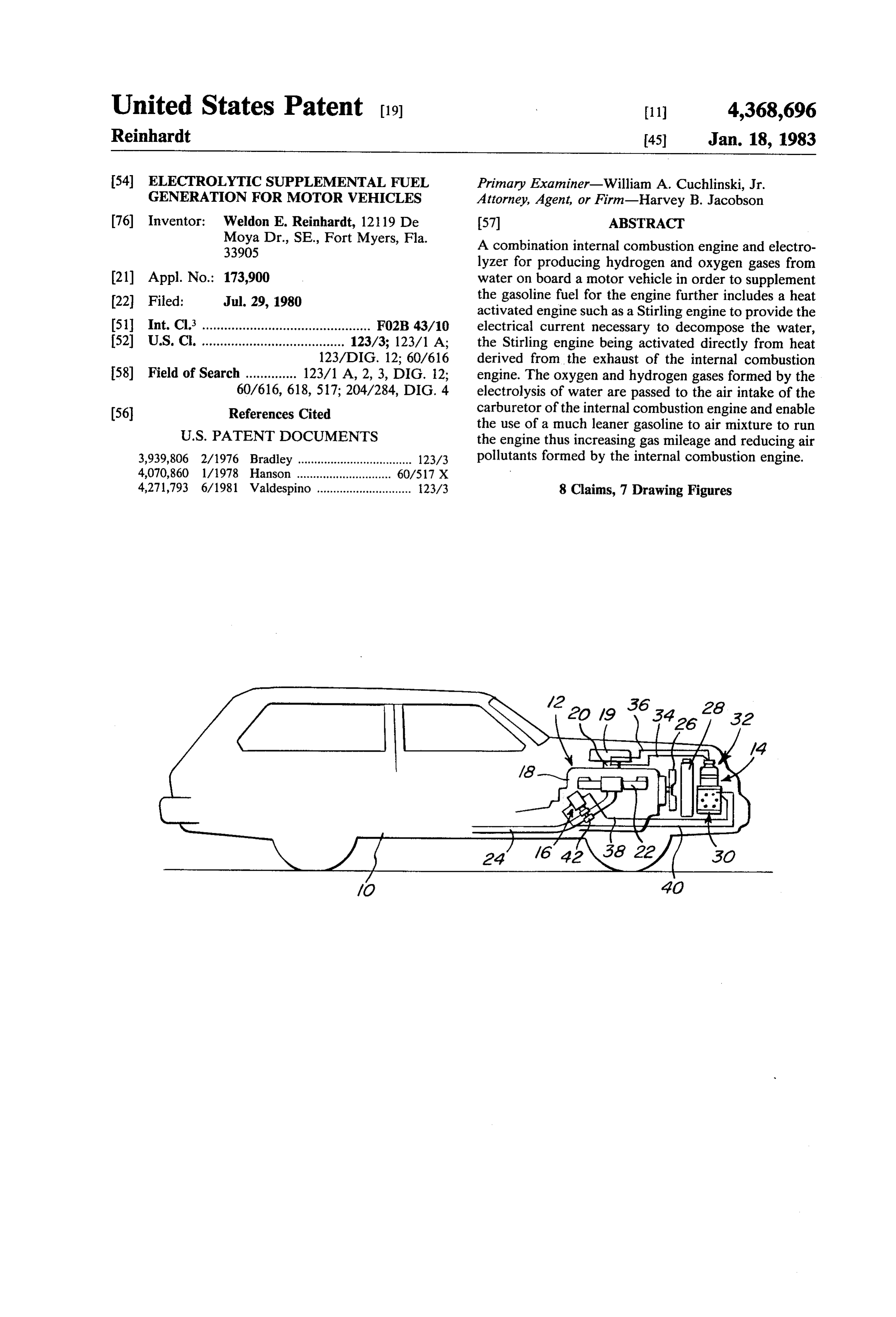
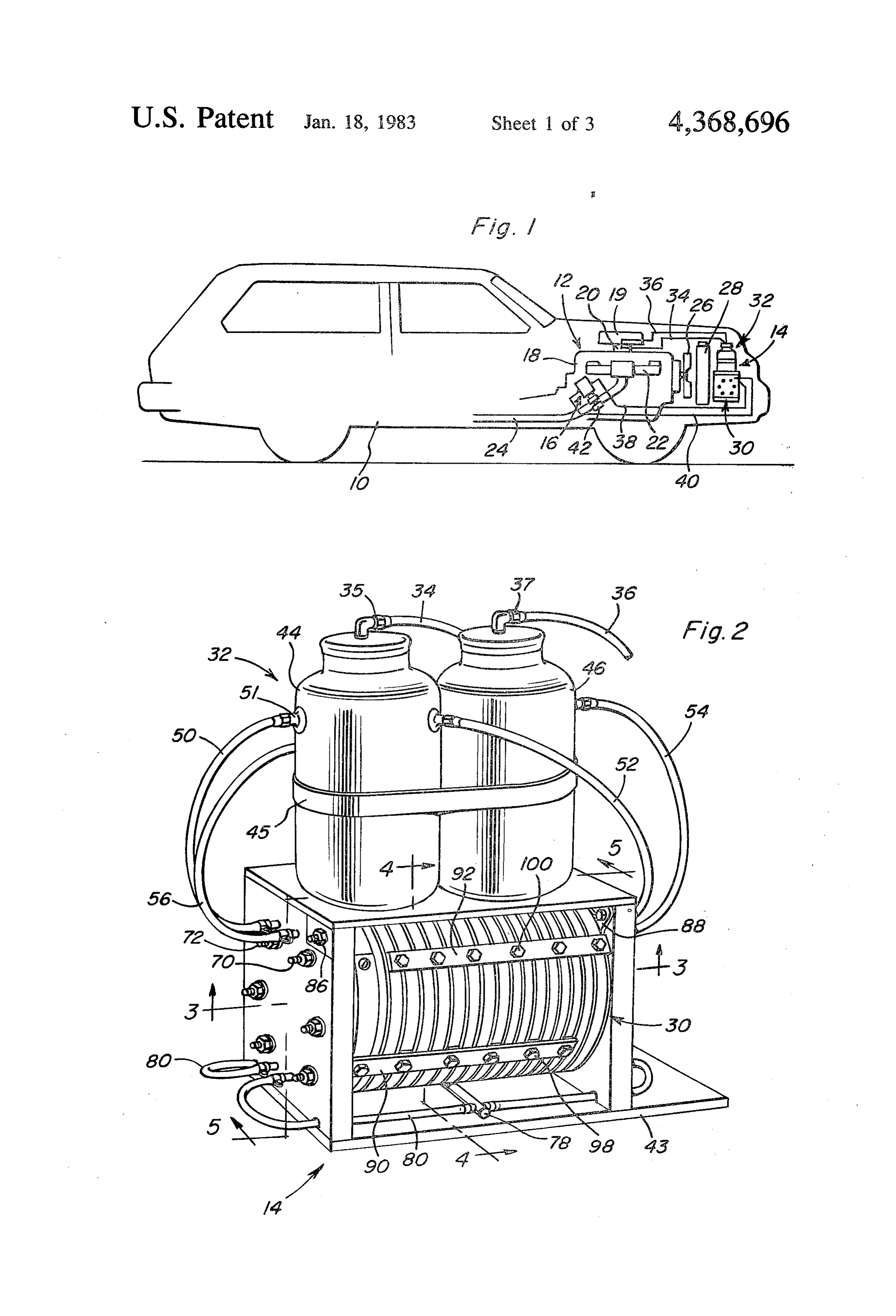
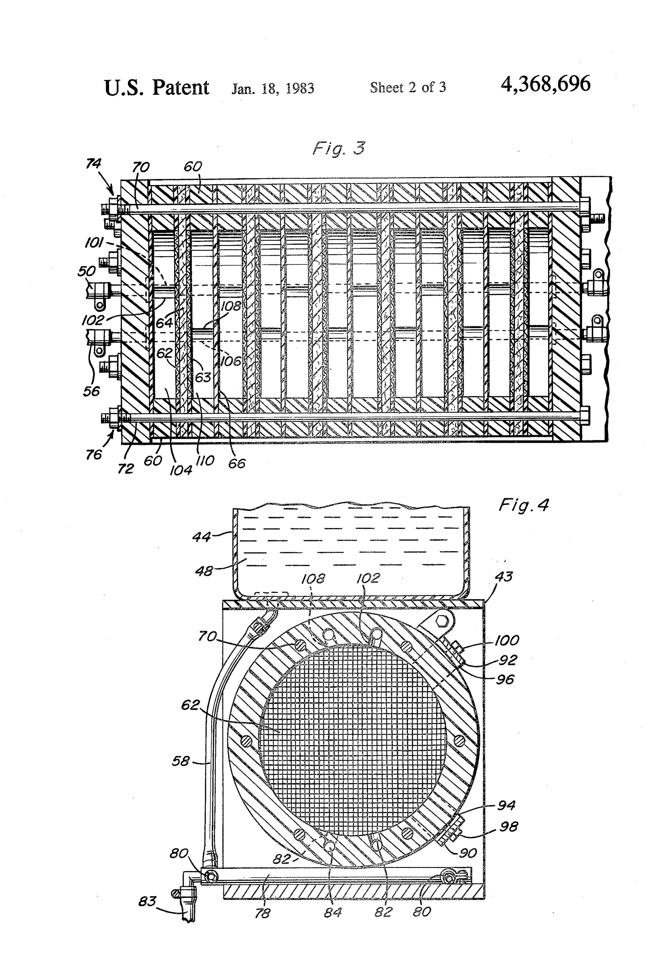
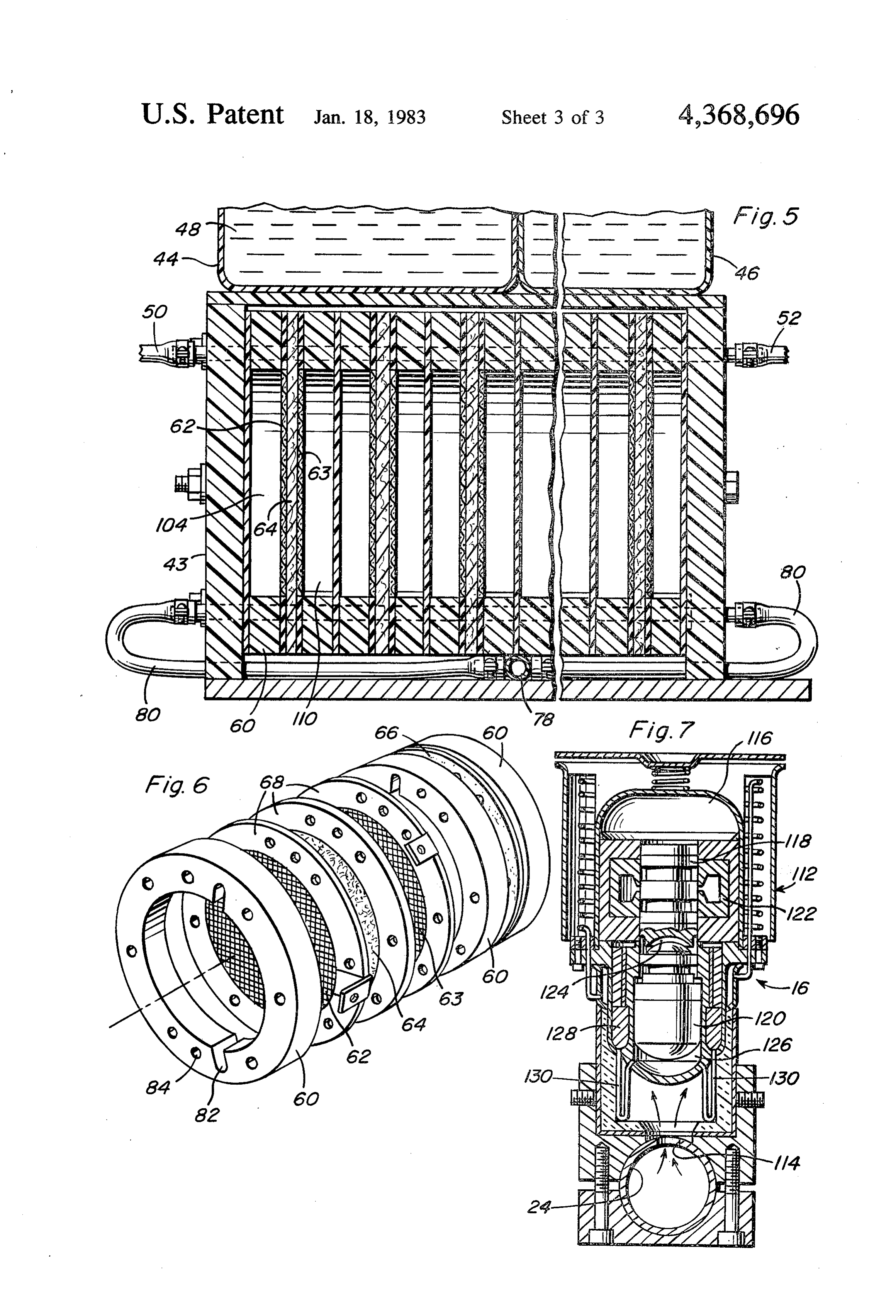
retors. While the present invention is broadly directed It is yet another object of the present invention to to supplementing the fuel for driving an internal con provide a device of the character aforesaid, in which bustion engine with hydrogen and oxygen gases derived 55 the heat activated linear alternator engine is able to from the electrolysis of water, the aforementioned pa derive its energy by direct heat exchange with the ex tents require cumbersome structure and operate by haust gases of the internal combustion engine. heating a working fluid to a gaseous state, the gas oper These together with other objects and advantages ating a turbine which runs a generator to produce the which will become subsequently apparent reside in the necessary electric current to decompose the water in 60 details of construction and operation as more fully here the electrolysis cell. The associated piping and heat inafter described and claimed, reference being had to exchange means required by this patented system makes the accompanying drawings forming a part hereof, it impractical for on-board use in motor vehicles. wherein like numerals refer to like parts throughout. In contrast, the present invention generates the elec tric current used to decompose the water by utilizing an 65 BRIEF DESCRIPTION OF THE DRAWINGS engine such as a Stirling engine which can be activated FIG. 1 is a schematic view illustrating the essential by direct heat exchange from the exhaust gases of the elements of the present invention on board a motor internal combustion engine. vehicle.
Page 6
FIG. 2 is a perspective view of the electrolyzer of the nator engine will generate electrical current by the present invention used to decompose water into its linear movement of the piston. The current is con separate gaseous components. ducted to electrolyzing system 30 which receives from FIG. 3 is a transverse sectional view of the electro storage and supply 32 the water or aqueous electrolyte lyzer taken generally along the line 3-3 of FIG. 2. solution. The water in the form of an electrolyte solu FIG. 4 is a transverse sectional view of the electro tion 48 in separate reservoir tanks 44, 46 is decomposed lyzer of the present invention taken generally along the into its hydrogen and oxygen gaseous components and line 4-4 of FIG. 2. conveyed back to separate reservoir tanks 44, 46 to the FIG. 5 is a longitudinal sectional view of the electro supply 32 whereupon the hydrogen and oxygen gases lyzer taken generally along the line 5-5 of FIG. 2. O are separately conveyed to carburetor 20. The supple FIG. 6 is an exploded perspective view illustrating mental hydrogen and oxygen gas fuel enables a much the individual components making up one cell of the leaner gasoline-to-air mixture to be used, resulting in electrolyzer of the present invention. greater fuel economy and greatly reduced air pollution. FIG. 7 is a cross-sectional view of the preferred heat Illustrated in FIGS. 2-6 is electrolyzer 14. Electro activated engine utilized in the supplemental fuel gener 15 lyzer 14 includes electrolyzing system 30 and storage ation system of the present invention shown in heat and supply system 32 supported on box-like frame struc exchange relation with the exhaust gas from an internal ture 43.
combustion engine. Storage and supply 32 comprises two tanks, hydro DETAILED DESCRIPTION OF THE gen supply tank 44 and oxygen supply tank 46, held INVENTION together by strap 45 and preferably made of plastic and The supplemental fuel generating device of the pres for which not only act as gas separators but as reservoirs ent invention can be easily installed on board any exist hydrogen aqueous electrolyte solution 48. Tank 44 receives gas from electrolyzing system 30 through ing automobile. Referring to FIG. 1, vehicle 10 is tubing 50 and 52 while tank 46 receives oxygen gas shown including internal combustion engine 12 and the 25 from tubing 54 and 56. Tubing 50, 52, 54 and 56 are supplemental fuel producing device of the present in joined to respective tanks 44 and 46 via a connector vention including electrolyzer 14 and the heat activated engine, 16 for generating the electric current used to such system as fitting 51. The gases produced in electrolyzing 30 are mixed with the electrolyte in the form of decompose the water. Internal combustion engine 12 foam which is pushed into the respective storage tanks containing engine block 18 has mounted thereon air 30 where the gases separate from the electrolyte and are filter 19 and carburetor 20 for receiving both hydrocar bon fuel such as gasoline and the supplemental hydro tion conveyed to the intake manifold of the internal combus gen and oxygen gas produced by electrolyzer 14. Car engine by respective tubing 34 and 36 fitted to tanks ried by engine block 18 is an exhaust manifold 22 from 44 and 46, respectively, by fittings 35 and 37. The elec which extends exhaust pipe 24. Engine block 18 in 35 trolyte is returned to electrolyzing system 30 by electro cludes a cooling system in accordance with accepted 4. lyte return tubing such as indicated at 58 shown in FIG. practice including fan 26 and radiator 28. The electrolyzing system or hydrogen-oxygen gener Electrolyzer 14 can be described as containing two systems, one system performing the electrolyzing func ator 30 is comprised of a series of high temperature tion indicated at 30 and the other system providing the 40 thermal set plastic discs 60 having about a 5-inch out storage for the electrolyte solution and the supply for side diameter and 3-inch inside diameter, see FIG. 6. the supplemental hydrogen and oxygen fuel, generally Between each two discs 60 is an electrode package of indicated at 32. Supply 32 contains separate hydrogen two solid nickel wire mesh electrodes 62 and 63 closely and oxygen transport hoses 34 and 36, respectively, for separated by an ion exchange membrane gas barrier 64. supply to carburetor 20. 45 Separating adjacent discs 60 is rubber or fiber glass Heat activated engine 16 is a heat activated motor separator 66 thus forming separate electrolysis cells, driven alternator used to generate linear rather than each cell comprising a pair of plastic discs 60 containing the electrode package therebetween. Electrodes 62 and sinusoidal alternations of electric current for the elec trolyzer 14. Electric current from the heat activated 63 and gas barrier 64 are sealed by a rubber gasket 68. engine 16 is conducted through a rectifier (not shown) 50 The electrolyzer 14 shown in FIGS. 2 and 3 is a 6-cell to change AC to DC current and then conducted by unit, the composite electrolyzer being secured by 6 conductors 38 and 40 to the individual electrode bolts threaded at each end and a washer and nut assem contacts contained on electrolyzer 14. The heat acti bly, such as bolts 70 and 72 and washer and nut assem vated motor driven alternator 16 is positioned adjacent blies 74 and 76 as shown in FIG. 3. exhaust pipe 24, or more preferably, an extension (not 55 In operation, aqueous electrolyte solution 48, such as shown) of exhaust pipe 24 by clamp 42. The preferred potassium hydroxide in distilled water is poured into heat activated engine is the Stirling free piston linear storage tanks 44 and 46 until each is about one-half full. alternator engine as shown in FIG. 7. The free piston The electrolyte solution passes to the cells through Stirling engine is preferred because of its ability to be electrolyte reservoir connection 58 and through elec scaled to particular specifications and be operated in trolyte return manifold 78 containing electrolyte return any position and therefore, it can accommodate the hoses 80 placed on both sides of electrolyzer system 30 space requirements of engine components making it and a drain 83 as shown in FIGS. 2 and 4. Each electro easily adaptable for on board motor vehicle use. lyte hose 80 supplies electrolyte solution to the cells by The operation of the supplement fuel generation sys providing an alternating system of ports 82 and passages tem of the present invention may be summarized by the 65 84 through plastic discs 60, electrolyte hoses 80 includ following explanation. Heat derived from exhaust mani ing the appropriate aperture at each port 82. Other fold 22 and exhaust pipe 24 is used to activate engine 16 electrolyte return systems may be used without depart which in the case of the Stirling free piston linear alter ing from the scope of the invention, it only being neces
Page 7
sary to maintain the proper level of electrolyte in each current. Also note the exhaust gases do not contact the cell for the generation of hydrogen and oxygen gases. piston faces of the piston of the Stirling engine. The decomposition of the electrolyte solution into The critical feature of the free piston Stirling engine separate hydrogen and oxygen gases is formed by the is the varying volume of the working space above and electric current generated by heat activated engine 16 5 below displacer 120. When gas pressure in compression which is conducted to electrical connectors 86 and 88 space 124 shoves displacer 120 down, gas in the hot end via conductors 38 and 40 from the alternator, thus com expansion space 126 is forced through regenerator 128 pleting the electric circuit. Electrodes 62 and 63 in each and into cold compression space 124. As the displacer cell are connected to a different electrical potential continues to move downward, the gas pressure in com through electrical conducting connectors 90 and 92 and 10 pression space 124 is overcome by the gas pressure in electric terminals 94 and 96 shown in FIGS. 2 and 4. gas spring 116 thus pushing power piston 18 down. Electrical conducting connectors 90 and 92 are secured However, the gas in the hot end expansion space 126 to electric terminals 94 and 96 respectively by means of has a greater pressure due to expansion caused by the nut and bolt assemblies 98 and 100. heat from the exhaust than the gas in compression space The hydrogen and oxygen gases are formed at elec 15 124, thus forcing the displacerback up pushing cold gas trodes 62 and 63, respectively, due to the differing elec from compression space 124 through the regenerator tric potential applied, each gas being conveyed to their 128 and heater tubes 130, returning heat to the gas. Gas respective storage tanks 44 and 46. As shown in FIG. 3, flowing into hot end expansion space 126 pushes up hose 50 conducting hydrogen gas to storage tank 44 displacer 120 and power piston 118. The gas pressure in includes a series of apertures 101 juxtaposed with port 20 the hot end expansion space 126 then drops and gas in 102 in plastic disc 60 which forms part of the cell unit compression space 124 bounces the displacer 120 back, indicated by 104. Oxygen transport hose 56 includes completing the cycle. The free piston Stirling engine aperture 106 juxtaposed with port 108 associated with illustrated in FIG. 7 is manufactured by Sunpower In cell half 110 and transports the formed oxygen at elec corporated in Athens, Ohio, the previous description trode 63 to the respective storage tank 46. Hydrogen 25 coming from a summary of trade literature. gas transport hose 50 is not open to cell half 110 which The combination of an electrolyzer to produce the does not include a hydrogen gas port through the disc hydrogen and oxygen gas with an engine which can 60. Each gas transport line is only open to a specific cell derive its energy from direct heat exchange with the half which will form the specific gas, enabling the hy exhaust gases of an internal combustion engine to gener drogen and oxygen gases to be separated and thus 30 ate the electrical current necessary to produce the gases stored separately and supplied separately to the intake is much lighter in weight and much less complex than of the internal combustion engine. As can be seen in prior art systems and, in particular, with the free piston FIGS. 2 and 3, the gas passes through the entire electro Stirling linear alternator which can be placed in any lyzer system 30 and out through both ends thereof. position enables the system to be easily accommodated Once the internal combustion engine is started, hot 35 on board a motor vehicle.
exhaust therefrom creates the motion force of heat acti The foregoing is considered as illustrative only of the vated engine 16, and thus the electric current for elec principles of the invention. Further, since numerous trolysis. The gases freed by the electrochemical action modifications and changes will readily occur to those push their way out through the respective gas ports and skilled in the art, it is not desired to limit the invention hoses, pushing the electrolyte solution ahead and form to the exact construction and operation shown and ing a foamed mixture of electrolyte and gas. The elec described, and accordingly, all suitable modifications trolyte is pushed into the storage tanks of storage and and equivalents may be resorted to, falling within the supply 32 whereupon the electrolyte and gases are sepa scope of the invention.
rated, the electrolyte returning to the electrolyzer sys What is claimed as new is as follows: tem 30 via electrolyte return connection 58. Hoses 34 45 1. A device in combination with an internal combus and 36 which supply the hydrogen and oxygen gas, tion engine for electrolytically supplying supplemental respectively, to the fuel intake can include control fuel thereto comprising means to produce oxygen and valves on respective fittings 35 and 37 to vary the spe hydrogen gas from water, said gas producing means cific amounts of each gas supplied to carburetor 20. having a separate tank system for storing an aqueous FIG. 7 illustrates a preferred heat activated engine 50 electrolyte solution in reservoirs and for separately which is used to generate for rectification the needed storing each component gas decomposed from the linear alternations of electric current for electrolysis. aqueous electrolyte solution, said gas producing means While any engine which can derive its energy from the further having an electrolyzing system including a se waste heat of the exhaust of an internal combustion ries of electrolysis cells having closely spaced elec engine is applicable, the Stirling free piston linear alter 55 trodes in a stacked array and including means piping nator, shown in FIG. 7 is the one which appears to be derived gases from the electrolysis cells to the respec the most adaptable for on-board motor vehicle use. tive reservoirs and means piping aqueous electrolyte While the Stirling engine illustrated herein is a commer solution from the reservoirs to the series of electrolysis cial product and is the subject of trade literature, a brief cells, said means forming said gases by the electrolysis description of its components is appropriate. The free 60 of water, said device further comprising a means to piston Stirling engine is generally indicated at 112 and is generate linear alternations of electrical current for shown clamped to exhaust pipe 24 or an extension from conduction to said gas producing means, said means to the exhaust pipe including aperture 114 therein to pro generate electrical current being activated by heat from vide the heat required to run the engine. The free piston exhaust means of said internal combustion engine, said Stirling engine comprises a gas spring 116, power piston 65 electrical generating means being positioned adjacent 118 and displacer 120, the linear movement of power said exhaust means, means for conducting said electrical piston 118 in conjunction with linear generator 122 current to said gas producing means and means to trans generating the needed linear alternations of electrical port said gases from the separate tank system to the
Page 8
internal combustion engine, each of the electrolyte cells trodes, means applying a different electrical potential to comprising a gas barrier performing as an ion exchange each of the electrodes in each of the cells for the cells to member when sandwiched between two solid nickel produce oxygen and hydrogen gas, separate storage wire mesh electrodes, hollow annular members in turn container means supplying water to the series of elec sandwiching the assembly of electrodes and the gas trolysis cells and separately collecting the oxygen and barrier, and an elastomeric gasket bounded and sealed hydrogen gas from the separate oxygen and hydrogen about said cells. ports, means to generate linear alternations of electrical 2. The device as set forth in claim 1 wherein said current coupled to the respective electrodes of the gas electrical generating means is so positioned to be acti producing means and the means generating electrical vated by direct heat exchange from exhaust gases from 10 current being so integrally positioned in the path of the said internal combustion engine without impact of ex exhaust gases of the internal combustion engine to be haust gas. activated by direct heat exchange means, and means to 3. The device as set forth in claim 1 wherein said transport said gases from the respective oxygen and electrical generating means is a linear generator in hydrogen ports to a carburetor of the internal combus which a piston is moved back and forth linearly solely 15 tion engine, each of the cells has their electrodes and the in response to the heat exchange from said exhaust gas barrier means sealed by a rubber gasket. gases. 6. A device in combination with an internal combus 4. A device in combination with an internal combus tion engine for electrolytically supplying supplemental tion engine for electrolytically supplying supplemental fuel thereto comprising means to produce oxygen and fuel thereto comprising means to produce oxygen and 20 hydrogen gas from water by the electrolysis of water hydrogen gas from water by the electrolysis of water and having a series of electrolysis cells, each of the cells and having a series of electrolysis cells, each of the cells having a pair of closely spaced electrodes contained in having a pair of closely spaced electrodes contained in a supply of water and further having separate oxygen a supply of water and further having separate oxygen and hydrogen ports for exiting the respective gases, the and hydrogen ports for exiting the respective gases, the 25 respective ports being positioned in each of the cells respective ports being positioned in each of the cells adjacent a respective one of the closely spaced elec adjacent a respective one of the closely spaced elec trodes, means applying a different electrical potential to trodes, means applying a different electrical potential to each of the electrodes in each of the cells for the cells to each of the electrodes in each of the cells for the cells to produce oxygen and hydrogen gas, separate storage produce oxygen and hydrogen gas, separate storage 30 container means supplying water to the series of elec container means supplying water to the series of elec trolysis cells and separately collecting the oxygen and trolysis cells and separately collecting the oxygen and hydrogen gas from the separate oxygen and hydrogen hydrogen gas from the separate oxygen and hydrogen ports, means to generate linear alternations of electrical ports, means to generate linear alternations of electrical current coupled to the respective electrodes of the gas current coupled to the respective electrodes of the gas 35 producing means and the means generating electrical producing means and the means generating electrical current being so integrally positioned in the path of the current being so integrally positioned in the path of the exhaust gases of the internal combustion engine to be exhaust gases of the internal combustion engine to be activated by direct heat exchange means, means to activated by direct heat exchange means, means to transport said gases from the respective oxygen and transport said gases from the respective oxygen and hydrogen ports to a carburetor of the internal combus hydrogen ports to a carburetor of the internal combus tion engine, each of the electrolyte cells comprising a tion engine, the series of electrolysis cells being com gas barrier performing as an ion exchange member prised of a series of high temperature thermal set plastic when sandwiched between two solid nickel wire mesh discs between a pair of which is an electrode package of electrodes, hollow annular members in turn sandwich two solid nickel wire mesh electrodes separate by an ion 45 ing the assembly of electrodes and the gas barrier, and exchange membrane gas barrier means and electrically an elastomeric gasket bounded and sealed about said insulating separator disc means interposed between an cells.
adjacent pair of discs. 7. The device as set forth in claim 1, 4, 5 or 6 wherein 5. A device in combination with an internal combus said electrical generating means comprises a free piston tion engine for electrolytically supplying supplemental 50 Stirling engine linear generator. fuel thereto comprising means to produce oxygen and 8. The invention of claims 1, 4, 5 or 6 wherein the gas hydrogen gas from water by the electrolysis of water producing means further contains a foamed mixture of and having a series of electrolysis cells, each of the cells an electrolyte and gas capable of being pushed into the having a pair of closely spaced electrodes contained in storage container means where the gases separate from a supply of water and further having separate oxygen 55 the electrolyte and the gases are conveyed through the and hydrogen ports for exiting the respective gases, the respective ports and conduit means return the electro respective ports being positioned in each of the cells lyte to the series of electrolysis cells. adjacent a respective one of the closely spaced elec k
Provenance
- Collection
- Cited prior art
- Original PDF
- patentimages.storage.googleapis.com →
- Filed
- 1980-07-29
- Pages
- 8
- Method
- pdftotext (the PDF's own text layer) + pdftoppm 300dpi page scans
- Source
- Google Patents bibliographic record
- Granted
- 1983-01-18
- Inventors
- Weldon E. Reinhardt
- Transcribed from
- patentimages.storage.googleapis.com →