patent · US5178119A
Combustion process and fuel supply system for engines
12 January 1993
Page 1 — bibliographic record
United States Patent (19) 11) Patent Number: 5,178,119 Gale (45) Date of Patent: Jan. 12, 1993 54) COMBUSTION PROCESS AND FUEL 4,306,532 12/1981 Camacho ............................ 23/527 SUPPLY SYSTEM FOR ENGINES 4,389,981 6/1983 Meyer ......... 123ADIG. 12 4,520,763 6/1985 Lynch et al. ........................... 123A 75) Inventor: Nigel F. Gale, San Antonio, Tex. 4,523,548 6/1985 Engel et al.............................. 123/ 4,570,578 2/1986 Peschka et al. ......................... 23/ 73) Assignee: Southwest Research Institute, San 4,715,326 12/1987 Thring .................................... 123A3 Antonio, Tex. 4,783,966 l/1988 Aldrich ................................. 60/622 21 Appl. No.: 804,996 FOREIGN PATENT DOCUMENTS 22) Filed: Dec. 11, 1991 0015924 2/1977 Japan ...................................... 123/3 51) Int. Cl. .............................................. FO2B 47/08 Primary Examiner-E. Rollins Cross 52 U.S. C. ........................... 123/570; 123/DIG. 12; Assistant Examiner-Erick Solis 123/568; 60/619 Attorney, Agent, or Firm-Baker & Botts 58) Field of Search ........... 123/3, 568, 570, DIG. 12; 57 ABSTRACT
(56) References Cited A fuel combustion process is provided for a multi-cylin der engine for reducing exhaust emissions of carbon
2.113,602 7/1933 Pratt ........................................ 123/1 includes the steps of introducing hydrocarbon fuel in a 3,808,818 5/1974 Cataldo .... ... 60/620 first engine cylinder, burning the hydrocarbon fuel and 3,896,774 7/1975 Siewert ................................. 23/59 producing exhaust gases, introducing the exhaust gases 3,918.412 11/1975 Lindstrom ... 123/568 in a second cylinder, introducing hydrogen in the sec 3,924.576 12/i975 Siewert ................................. 60/62O ond cylinder, and burning the hydrogen with the ex 3,941,113 3/1976 Baguelin ... ... 123A179.2 haust gases, thereby producing exhaust emissions hav 3,958,540 5/1976 Siewert ................................, 123/59 ing a lower carbon monoxide and unburned hydrocar 4,059,076 A977 Rosaka et al. ... 123/3 4,159,700 7/1979 McCrum ...... ... 60/619 bon content than that of the exhaust gases produced in 4.175,523 11/1979 Noguchi. ... .23/3 the first cylinder.
4,198,940 4/1980 Ishida ........... 123/119 4,244.328 1/1981 Lindstrom .............................. 123A3 14 Claims, 2 Drawing Sheets
Page 2
Drawing sheet — no readable text.
Page 3
Drawing sheet — no readable text.
Page 4
unburned hydrocarbon content than that of the exhaust
COMBUSTION PROCESS AND FUEL SUPPLY gases produced in the first cylinder. SYSTEM FOR ENGINES In another aspect, this invention provides an in proved engine fuel supply system for an internal com
TECHNICAL FIELD OF THE INVENTION 5 bustion engine having first and second combustion This invention relates generally to engines. More chambers. The improved fuel supply system is provided particularly, but not by way of limitation, this invention for reducing exhaust emissions of oxides of nitrogen, relates to fuel supply systems and combustion processes unburned hydrocarbons and carbon monoxide. The for internal combustion engines utilizing hydrogen and 10 system includes means for supplying fuel to the first hydrocarbon fuels. combustion chamber, means for igniting the fuel in the first combustion chamber, thereby producing exhaust
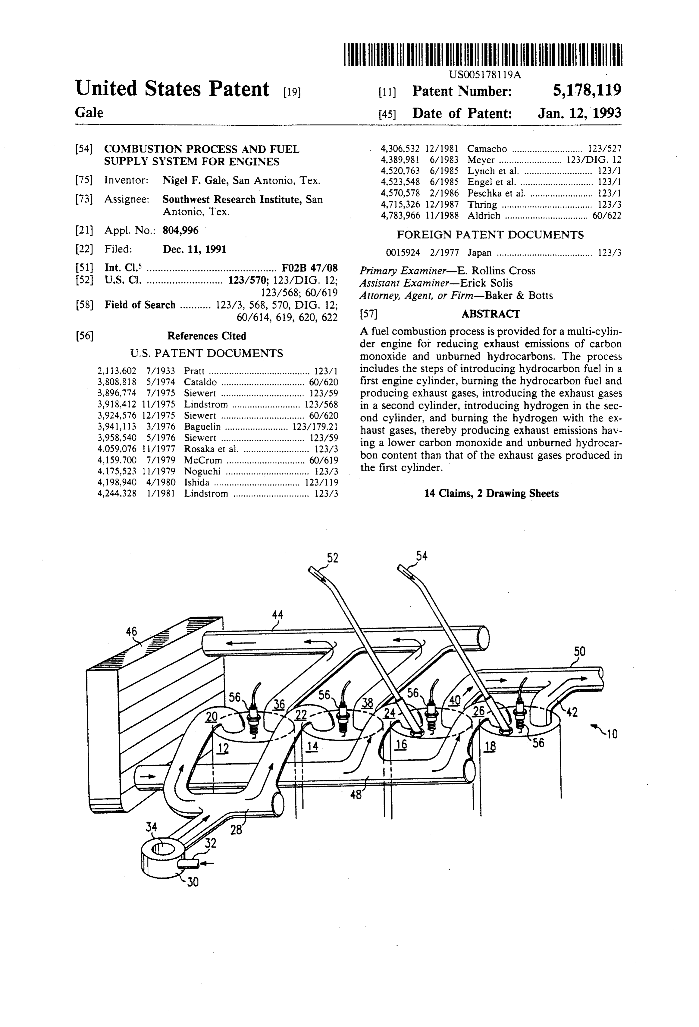
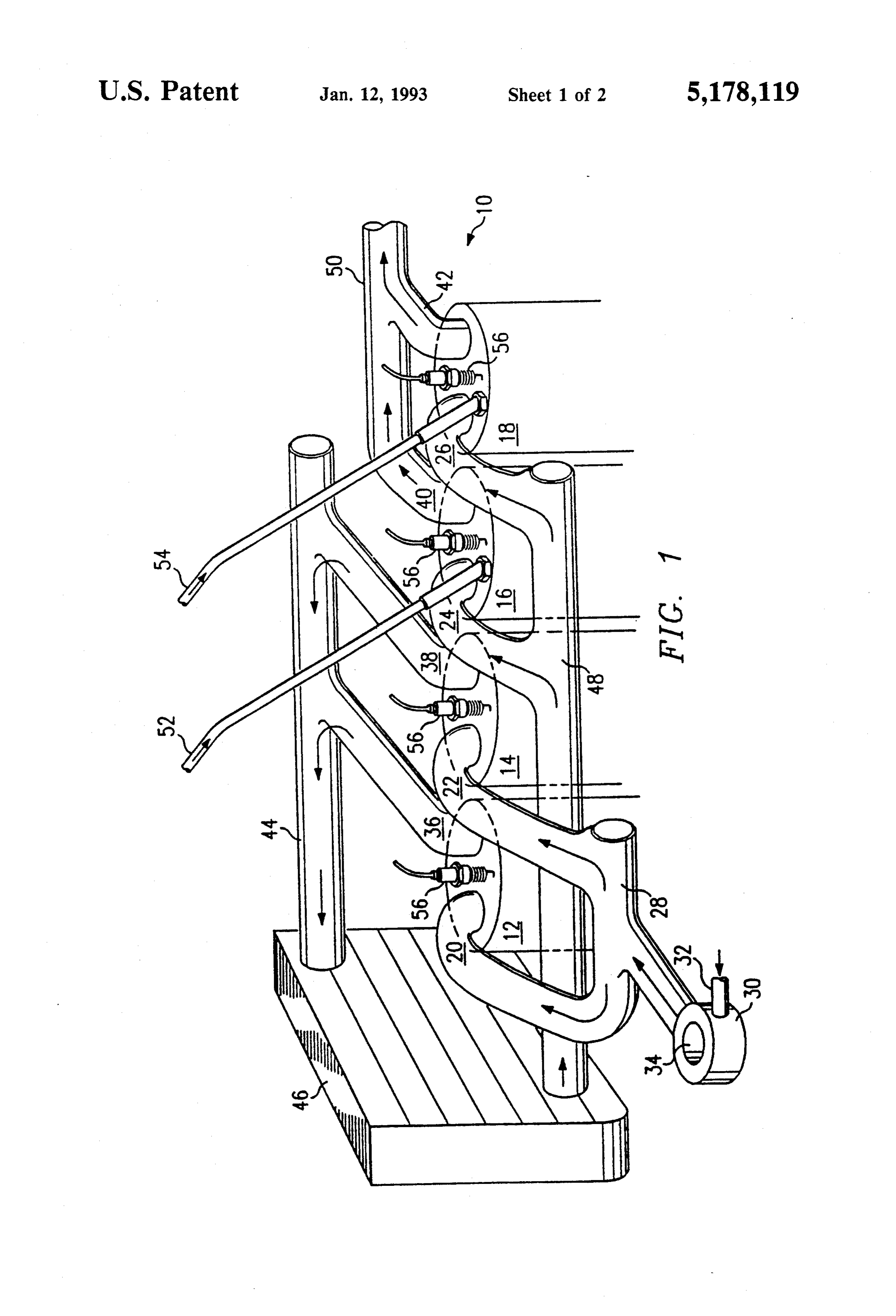
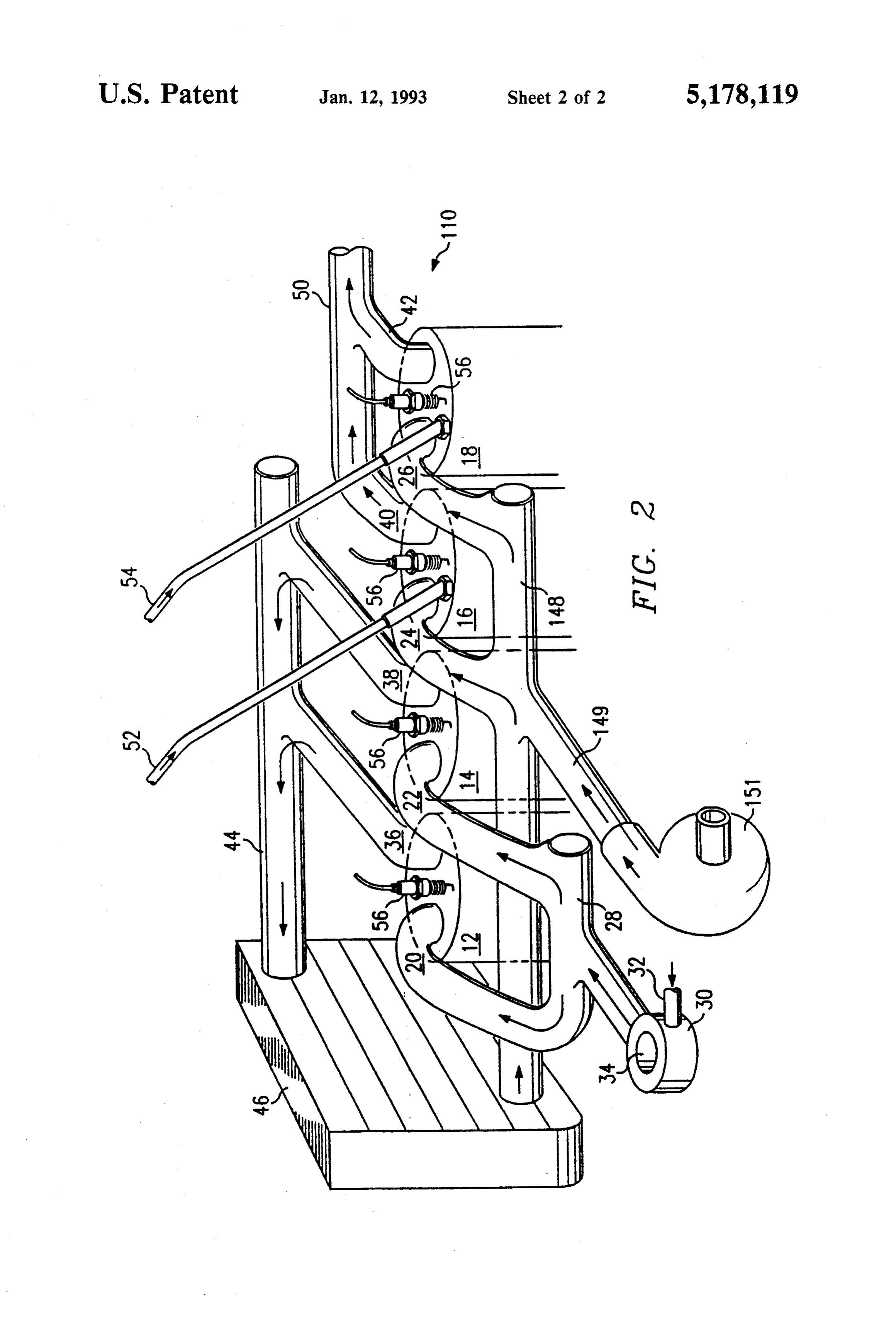
BACKGROUND OF THE INVENTION gases containing carbon monoxide and unburned hy Normally when hydrocarbon fuels are burned in drocarbons, means for delivering the exhaust gases from internal combustion engines, exhaust gases are pro the first combustion chamber to the second combustion duced containing significant quantities of pollutants like 15 chamber, means for introducing hydrogen to the second carbon monoxide, oxides of nitrogen and unburned combustion chamber, and means for igniting the ex hydrocarbons. Typically, after-treatment devices like haust gases and hydrogen, thereby producing exhaust oxidizing catalysts are used to reduce the pollutant emissions having a lower unburned hydrocarbon and content of the exhaust. However, an engine producing carbon monoxide content than the exhaust gases pro significant amounts of unburned hydrocarbons will duced in the first combustion chamber. have a low energy efficiency. A technical advantage of this invention is that it pro Attempts have been made in the past to cause more vides combustion process and a fuel supply system for complete combustion of hydrocarbon fuels in internal an engine that significantly reduces exhaust emissions of combustion engines. For example, U.S. Pat. No. 25 carbon monoxide and unburned hydrocarbons without 4,198,940 issued to Ishida; U.S. Pat. No. 2, 3,602 is the need for after-treatment devices. sued Pratt; U.S. Pat. No. 4,059,076 issued to Kosaka and Another technical advantage of this invention is that U.S. Pat. Nos. 3,958,540; 3,896,774; and 3,924,576 issued it provides an improved fuel supply system and a com to Siewert all disclose internal combustion engines, in bustion process for an engine using hydrogen and hy which exhaust from one cylinder of the engine is deliv 30 drocarbon fuels that produces essentially the same ex ered to and burned in a second cylinder to reduce the haust emissions as an engine burning only hydrogen. emission of unburned hydrocarbons. Thus, the amount of hydrogen needed for the operation When hydrogen is burned in an internal combustion of the engine is significantly reduced. engine, the exhaust generally comprises only water vapor and the oxides of nitrogen. It has been found that 35 BRIEF DESCRIPTION OF THE DRAWINGS the emissions of the oxides of nitrogen can be reduced if The foregoing and additional objects and advantages the oxygen content of the charge is reduced to an of the invention will become more apparent as the fol amount below that normally present in the air. Thus, lowing detailed description is read in conjunction with engines using hydrogen can be operated to produce the accompanying drawings, wherein like reference exhaust gases having a very low pollutant content. 40 characters denote like parts in all views and wherein; However, hydrogen is expensive to produce and occu FIG. 1 illustrates a fuel supply system constructed in pies approximately four times the volume of hydrocar accordance with one embodiment of the invention that bon fuel of the same energy potential. can be utilized with a lean fuel/air mixture; and An object of this invention is to provide an improved FIG. 2 illustrates a fuel supply system constructed in fuel supply system and combustion process for an inter 45 accordance with another embodiment of the invention nal combustion engine burning hydrocarbon fuel that that can be utilized with a rich fuel/air mixture. significantly reduces exhaust emissions of carbon mon DETAILED DESCRIPTION OF THE oxide, oxides of nitrogen and unburned hydrocarbons NVENTION w without the need for after-treatment devices.
Another object of this invention is to provide an 50 FIG. 1 illustrates a fuel supply system constructed in improved fuel supply system and combustion process accordance with one embodiment of the invention for for an internal combustion engine, enabling the engine use with an engine, which is generally designated by to use hydrogen and hydrocarbon fuels to produce reference character 10. The engine 10 includes a plural exhaust gases having a low pollutant content similar to ity of cylinders 12, 14, 16 and 18, each comprising a exhaust gases produced by an engine burning only hy 55 combustion chamber for the engine. Each of the cylin drogen. ders 12, 14, 16 and 18 is provided with an intake port
SUMMARY OF THE INVENTION
connected to intake pipes 20, 22, 24 and 26, respec tively. The intake pipes 20 and 22 are connected to an
In one aspect, this invention provides an improved intake manifold 28, which in turn is connected to a fuel combustion process that reduces emissions of ox carburetor 30. The carburetor 30 is provided for mixing ides of nitrogen, unburned hydrocarbons and carbon fuel and air and delivering the fuel/air mixture to the monoxide. The process includes the steps of introducing cylinders 12 and 14. A fuel pipe 32 is connected to the hydrocarbon fuel in a first engine cylinder, burning the carburetor 30 for supplying hydrocarbon fuel to the hydrocarbon fuel and producing exhaust gases, intro carburetor 30. Air to be mixed with the fuel is drawn ducing the exhaust gases in a second cylinder, introduc 65 into the carburetor 30 through an opening 34 therein. ing hydrogen in the second cylinder, and burning the While the drawing illustrates the use of a carburetor hydrogen with the exhaust gases, thereby producing fuel system, the fuel system may be a natural gas system exhaust emissions having a lower carbon monoxide and with its attendant controls or may be a fuel injection
Page 5
system. If desired, the air taken into the engine may be into the exhaust manifold 50 and then released into the filtered. atmosphere.
Each of the cylinders 12, 14, 16, and 18 is provided Each of the cylinders 12, 14, 16 and 18 supplies the with an exhaust port connected to exhaust pipes 36, 38, output power of the engine. It should be noted that 40 and 42, respectively. The exhaust pipes 36 and 38 are while four cylinders are shown in the embodiment of connected to a pipe 44, which delivers exhaust gases FIG. 1, any number of cylinders can be provided. Also, from the cylinders 12 and 14 to a heat exchanger or an the number of cylinders burning only hydrocarbon fuel intercooler 46 provided for cooling the exhaust gases. need not be the same number of cylinders burning the An intake manifold 48 is connected to the intercooler 46 combination of exhaust gases and hydrogen. It should and to the intake pipes 24 and 26 for allowing exhaust 10 be further noted that while FIG. 1 shows a spark igni gases passing through the intercooler 46 to be delivered tion engine, a compression ignition engine may be pro to the cylinders 16 and 18. vided so that diesel fuel may be utilized as the hydrocar The exhaust pipes 40 and 42, which extend from the bon fuel. In addition, it should be noted that hydrocar cylinders 16 and 18, respectively, are connected to an bon derivatives like alcohol may be used for the hydro exhaust manifold 50, which releases exhaust gases from 15 carbon fuel.
the cylinders 16 and 18 into the atmosphere. The Embodiment of FIG. 2 The cylinders 16 and 18 are each provided with a hydrogen intake port connected to hydrogen intake FIG. 2 illustrates an embodiment of the invention pipes 52 and 54, respectively. Hydrogen intake pipes 52 similar to the FIG. 1 embodiment, but suitable for use and 54 are connected to a hydrogen source (not shown), 20 with rich fuel/air mixtures. FIG. 2 illustrates a fuel which supplies hydrogen to the cylinders 16 and 18. supply system for an engine generally designated by Each of the cylinders 12, 14, 16 and 18 is provided reference character 110. The engine 110, like the engine with a spark plug 56 or similar fuel igniting device for 10, includes the plurality of cylinders 12, 14, 16 and 18, initiating the combustion of fuel in the cylinders. Al each comprising a combustion chamber for the engine though not shown, it will be understood that appropri 25 110. Each of the cylinders 12, 14, 16 and 18 is provided ate fuel control or throttling devices and appropriate with an intake port connected to the intake pipes 20, 22, ignition controls will be provided for the engine 10. 24 and 26, respectively. The intake pipes 20 and 22 are Operation of the Embodiment of FIG. 1 connected to the intake manifold 28, which in turn is connected to the carburetor 30. The carburetor 30 is
In the operation of the engine 10, a lean hydrocarbon 30 provided for mixing fuel and air and delivering the fuel/air mixture having excess air is formed in the car fuel/air mixture to the cylinders 12 and 14. The fuel buretor 30 and delivered to the cylinders 12 and 14 pipe 32 is connected to the carburetor 30 for supplying through intake pipes 20 and 22, respectively. In the hydrocarbon fuel to the carburetor 30. Air to be mixed cylinders 12 and 14, the fuel/air mixture is ignited by with the fuel is drawn into the carburetor 30 through the spark plugs 56, producing exhaust gases containing 35 the filtered opening 34 therein. oxygen, oxides of nitrogen, carbon monoxide and un Each of the cylinders 12, 14, 16 and 18 is provided burned hydrocarbons. Because a lean fuel/air mixture is with an exhaust port connected to exhaust pipes 36,38, used, the exhaust contains reduced amounts of carbon 40 and 42, respectively. The exhaust pipes 36 and 38 are monoxide and oxides of nitrogen. The exhaust gases connected to a pipe 44, which delivers exhaust gases flow through exhaust pipes 36 and 38, into pipe 44 and from the cylinders 12 and 14 to the heat exchanger or through the intercooler 46. In the intercooler 46, the intercooler 46. An intake manifold 148 is connected to exhaust gas temperature is lowered so that premature the intercooler 46 and to the intake pipes 24 and 26 for combustion will not occur when the exhaust gases are delivering exhaust gases passing through the intercooler later introduced into cylinders 16 and 18 with hydro 46 to the cylinders 16 and 18. The intake manifold 148 gen. 45 is also connected to an air intake pipe 149, which Upon leaving the intercooler 46, the exhaust gases supplies additional air to the cylinders 16 and 18 from a flow through the intake manifold 48 and into the cylin supercharger or turbocharger 151.
ders 16 and 18. At the same time, hydrogen is injected The exhaust pipes 40 and 42, which extend from the into the cylinders 16 and 18 through the hydrogen in cylinders 16 and 18, respectively, are connected to the take pipes 52 and 54, respectively. The cylinders 16 and 50 exhaust manifold 50, which releases exhaust gases from 18 now contain a combination of exhaust gases and the cylinders 16 and 18 into the atmosphere. The cylin hydrogen, which is then ignited by spark plugs 56. The ders 16 and 18 are each provided with a hydrogen in resulting combustion in the cylinders 16 and 18 causes take port connected to hydrogen intake pipes 52 and 54, oxidation of the carbon monoxide present in the cylin respectively. Hydrogen intake pipes 52 and 54 are con ders 16 and 18, forming carbon dioxide. The combus 55 nected to a hydrogen source (not shown), which tion also causes burning of the unburned hydrocarbons supplies hydrogen to the cylinders 16 and 18. present in the exhaust gases. Thus, the resulting exhaust Each of the cylinders 12, 14, 16 and 18 is provided emissions from the cylinders 16 and 18 include substan with a spark plug 56 or similar fuel igniting device for tially reduced quantities of carbon monoxide and un initiating combustion of fuel in the cylinders. Although burned hydrocarbons as compared to the exhaust gases 60 not shown, it will be understood that appropriate fuel produced by the cylinders 12 and 14. The combustion of control or throttling devices and appropriate ignition hydrogen in the cylinders 16 and 18 produces emissions controls will be provided for the engine 110. of essentially water vapor and small quantities of oxides of nitrogen. Since the oxygen content of the exhaust Operation of the Embodiment of FIG. 2 gases from the cylinders 12 and 14 is lower than that 65 In the operation of the engine 110, a rich fuel/air normally present in the air, emissions of the oxides of mixture well above the stoichiometric range is formed nitrogen are reduced. The exhaust produced from cylin in the carburetor 30 and delivered to the cylinders 12 ders 16 and 18 is fed through the exhaust pipes 40 and 42 and 14 through intake pipes 20 and 22, respectively. In
Page 6
the cylinders 12 and 14, the fuel/air mixture is ignited ide and unburned hydrocarbons, the process comprising by the spark plugs 56, producing exhaust gases contain the steps of:
ing oxides of nitrogen, carbon monoxide and unburned introducing hydrocarbon fuel in a first engine cylin hydrocarbons. Since the fuel/air mixture is hydrocar der;
bon rich, few oxides of nitrogen are produced during burning the hydrocarbon fuel in the first engine cylin combustion. However, a substantial amount of un der, thereby producing exhaust gases containing burned hydrocarbons and carbon monoxide emissions carbon monoxide, unburned hydrocarbons and are produced. oxides of nitrogen;
The exhaust gases produced from the cylinders 12 introducing the exhaust gases into a second engine and 14 flow through the exhaust pipes 36 and 38, into O cylinder;
pipe 44 and through the intercooler 46. In the inter introducing hydrogen in the second engine cylinder; cooler 46, the exhaust gas temperature is lowered so and that premature combustion will not occur when the burning the hydrogen with the exhaust gases in the exhaust gases are later introduced into the cylinders 16 second cylinder to produce exhaust emissions hav and 18 with hydrogen. 15 ing a lower carbon monoxide and unburned hydro
Upon leaving the intercooler 46, the exhaust gases carbon content than the exhaust gases produced in flow through the intake manifold 148 and into the cylin the first cylinder.
ders 16 and 18. Since the fuel/air mixture burned in the 2. The method of claim 1, further including the step cylinders 12 and 14 was hydrocarbon rich, there is in of cooling sufficient excess oxygen in the exhaust necessary for 20 der prior tothesaid exhaust gases produced in the first cylin step of introducing the exhaust gases proper combustion in the cylinders 16 and 18. Conse into the second cylinder to inhibit premature combus quently, added air is supplied to the cylinders 16 and 18 tion of the exhaust gases and the hydrogen in the second through the air intake pipe 149 from the supercharger cylinder.
or turbocharger 151. At the same time, hydrogen is 3. The method of claim 1, wherein said step of intro injected into the cylinders 16 and 18 through the hydro 25 ducing hydrocarbon fuel in a first cylinder comprises gen intake pipes 52 and 54, respectively. The cylinders introducing a rich hydrocarbon fuel and air mixture in 16 and 18 now contain a combination of exhaust gases, the first cylinder to reduce the generation of oxides of hydrogen and added air, which is then ignited by the nitrogen and wherein the method further comprises spark plugs 56. The resulting combustion in the cylin ders 16 and 18 causes oxidation of carbon monoxide, 30 introducing air into the second cylinder prior to said forming carbon dioxide. The combustion also causes step of burning the hydrogen with the exhaust gases in burning of unburned hydrocarbons present in the ex the second cylinder.
haust gases. Thus, the resulting exhaust emissions from ducing 4. The method of claim 1, wherein said step of intro the cylinders 16 and 18 include substantially reduced hydrocarbon fuel in a first cylinder comprises quantities of carbon monoxide and unburned hydrocar 35 introducing a lean hydrocarbon fuel and air mixture in bons as compared to the exhaust gases produced by the the first cylinder to reduce generation of carbon monox cylinders 12 and 14. The combustion of hydrogen in the ide and oxides of nitrogen.
cylinders 16 and 18 produces emissions of essentially 5. The method of claim 1, wherein said step of intro water vapor and the oxides of nitrogen. The exhaust ducing hydrocarbon fuel in a first cylinder comprises produced from the cylinders 16 and 18 is fed through introducing gasoline in the first cylinder. the exhaust pipes 40 and 42, into the exhaust manifold 50 6. The method of claim 1, wherein said step of intro and then released into the atmosphere. ducing hydrocarbon fuel in a first cylinder comprises Each of the cylinders 12, 14, 16 and 18 supplies out introducing diesel fuel in the first cylinder. put power of the engine 110. It should be noted that 7. The method of claim 1, wherein said step of intro while four cylinders are shown in the embodiment of 45 ducing hydrocarbon fuel in the first cylinder comprises FIG. 2, any number of cylinders may be used. Also, the introducing alcohol in the first cylinder. number of cylinders burning only hydrocarbon fuel 8. An engine fuel supply system for reducing exhaust need not be the same number of cylinders burning a emissions of unburned hydrocarbons and carbon mon combination of exhaust gases and hydrogen. In addi oxide from an internal combustion engine having first tion, it should be noted that hydrocarbon derivatives 50 and second combustion chambers, the fuel supply sys like alcohol may be used for the hydrocarbon fuel. ten comprising:
The FIG. 2 embodiment may be operated with both means for supplying fuel to the first combustion lean and rich fuel/air mixtures to control the power chamber;
output of the engine 110. At a light load, a lean fuel/air means for igniting the fuel in the first combustion mixture could be provided to the cylinders 12 and 14 of 55 chamber, thereby producing exhaust gases contain the engine 110 with no added air from the supercharger ing carbon monoxide, unburned hydrocarbons and or turbocharger 151. At a full load, a rich fuel/air mix oxides of nitrogen;
ture could be supplied to the engine 110 along with means for delivering the exhaust gases from the first additional air from the supercharger or turbocharger combustion chamber to the second combustion 151. chamber;
The foregoing embodiments, which have been de means for introducing hydrogen to the second com scribed in detail, are presented by way of example only bustion chamber; and and it will be understood that many changes and modifi means for igniting the exhaust gases and hydrogen in cations can be made thereto without departing from the the second combustion chamber, thereby produc spirit of the invention. 65 ing exhaust emissions having a lower unburned What is claimed is: hydrocarbon and carbon monoxide content than 1. A fuel combustion process for a multi-cylinder the exhaust gases produced from the first combus engine for reducing exhaust emissions of carbon monox tion chamber.
Page 7
9. The engine fuel supply system of claim 8, wherein 13. The engine fuel supply system of claim 8, wherein said means for delivering the exhaust gases from the said means for supplying the fuel comprise means for first combustion chamber to the second combustion supplying a lean hydrocarbon fuel and air mixture for chamber include means for eooling the exhaust gases to reducing the generation of carbon monoxide and oxides inhibit premature combustion of the gases when intro of nitrogen in the first chamber. duced to the second combustion chamber with the hy 14. A fuel combustion process for a multi-cylinder drogen. internal combustion engine for reducing exhaust emis 10. The engine fuel supply system of claim 9, wherein sions of oxides of nitrogen, the process comprising: said means for cooling the exhaust gases comprise a heat burning hydrocarbon fuel in a first cylinder of the exchanger. O engine to generate exhaust gases having an oxygen 11. The engine fuel supply system of claim 8, wherein content less than that of air; said means for supplying the fuel comprise means for introducing the exhaust gases into a second cylinder Supplying a rich hydrocarbon fuel and air mixture for of the engine;
reducing the generation of oxides of nitrogen in the first introducing hydrogen into the second cylinder; and chamber and wherein the fuel supply system further 15 burning the hydrogen and exhaust gases in the second comprises means for supplying air to the second com cylinder, thereby producing exhaust emissions hav bustion chamber. ing a lower oxides of nitrogen content than exhaust 12. The engine fuel supply system of claim 11, gases that would be produced if the hydrogen were wherein said means for supplying air comprise a turbo burned with air.
charger. 20 s
Provenance
- Collection
- Patents citing this work
- Original assignee
- Southwest Research Institute SwRI
- Pages
- 7
- Method
- pdftotext (the PDF's own text layer) + pdftoppm 300dpi page scans
- Patent office record
- patents.google.com →
- Source
- Google Patents citing-documents table
- Inventors
- Nigel F. Gale; Southwest Research Institute SwRI
- Published
- 1993-01-12
- Transcribed from
- patentimages.storage.googleapis.com →