patent · US4523548
Gaseous hydrocarbon fuel storage system and power plant for vehicles
18 June 1985
Page 1 — bibliographic record
United States Patent (19) 11) Patent Number: 4,523,548 Engel et al. (45) Date of Patent: Jun. 18, 1985 (54) GASEOUS HYDROCARBON FUEL OTHER PUBLICATIONS
STORAGE SYSTEMAND POWER PLANT
FOR VEHICLES "The Quest for Alternative Fuels," Detroit Engineer, (75) Inventors: Larry J. Engel, Rochester; John W. Nov. 1983, pp. 6-9.
Turko, River Rouge, both of Mich. "Sorbent-Containing Storage Systems for Natural Gas Powered Vehicles' by Amos Golovoy, Ford Motor (73) Assignee: Michigan Consolidated Gas Company, Dearborn, Mich. Company, Detroit, Mich. "Properties of Natural Zeolites', U.S. Dept. of the Interior, RI 7744, Bureau of Mines Report of Investiga 21 Appl. No.: 484,520 tions/1973.
22 Filed: Apr. 13, 1983 (List continued on next page.) (51) Int. Cl. .............................................. FO2B 43/OO Primary Examiner-E. Rollins Cross (52) U.S. Cl. .................................... 123/1 A; 123/527; Attorney, Agent, or Firm-Harness, Dickey & Pierce
58 Field of Search ............... 123/1 A, 525,527, 559, (57) ABSTRACT 123/528; 48/190; 206/0.6,0.7 A low pressure gaseous hydrocarbon fuel storage sys 56 References Cited tem and power plant is described, which generally com
2,681, 167 6/1954 Weisz ...................................... 222A3 gaseous hydrocarbon fuel, a prime mover, means for 2,712,730 7/1955 Spangler ............................... 48/190 conveying the gaseous hydrocarbon fuel to and from 2,882,243 4/1959 Milton ............. 252/455 X the storing means, and means for controlling the flow of 3,688,755 9/1972 Grayson et al. .................... 123/527 the gaseous hydrocarbon fuel from the storing means to 3,719,196 3/1973 McJones ............................, 137/256 the prime mover. The storing means, which may in 3,789,820 2/1974 Douglas et al. .................... 123/1 A clude one or more vessels or cylinders, contains a pre 3,807,422 4/1974 McJones ............................. 37/256 determined sorbent material for reducing the pressure 3,844,306 10/1974 Hill .......................................... 222/6 at which a given amount of the gaseous hydrocarbon 3,847,173 1/1974 Hill .......................................... 222/6 fuel is stored. The prime mover, such as an internal 3,849,086 l/1974 Johnson .............. 123/559 combustion engine, has means for combining the gase 3,906,915 9/1975 Bednarczyk et al..................., 123/3 ous hydrocarbon fuel with air to produce the mechani
3,960,769 6/1976 Munzner et al. ... ... 252A45 cal energy therefrom necessary to move the vehicle. 4,016,836 4/1977 MacKay et al. .................... E23/ A The conveying means is adapted to convey the gaseous 4,046,709 9/1977 Yuki .................................... 252/.445 hydrocarbon fuel to the storing means from a stationary 4,068,639 l/1978 Cook ................................... 123/1 A source of the gaseous hydrocarbon fuel, and also to 4,167,920 9/1979 Lepera et al. ...... ... 123/1 A convey the gaseous hydrocarbon fuel from the storing 4,178,882 12/1979 Anderson et al. .................. 123/1 A means to the combining means of the prime mover 4,225,320 9/1980 Gell ............. ... 206/0.6 4,227,497 10/1980 Mathieson ........................... 123/525 during the operation of the vehicle. In the preferred 4,253,428 3/1981 Billings et al. ... 123/. A embodiment, the maximum pressure at which the gase 4,287,166 9/1981 Dwyer ............ 252/455 Z ous hydrocarbon fuel is stored in the storing means is in 4,341,234 7/1982 Meinass et al. ......................... 222/6 the range of approximately 100 psig (689 kPa) to ap 4,343,770 8/1982 Simons ............ ... 206/0.7 proximately 400 psig (2760 kPa). 4,433,664 2/1984 Rodrigues ........................... 123/527
FOREIGN PATENT DOCUMENTS
162226 12/1981 Japan .................................. 23/1 A 45 Claims, 13 Drawing Figures
Page 2
"Natural Gas Storage With Zeolites" by Ronald A. "Compressed Natural Gas (CNG): A Vehicle Fuel For Munson and Robert A. Clifton, Jr.-Bureau of Mines Utility Company Fleets-The Pros and Cons'-Ameri Nonmetallic Minerals Program, U.S. Dept. Interior, can Gas Association-Feb. 1982, 8/71. "Assessment of Methane-Related Fuels For Automo "Natural Zeolites: Their Properties, Occurrences, and tive Fleet Vehicles'-U.S. Dept. of Energy-Feb. 1982, Uses"-R. A. Munson and R. A. Sheppard, Minerals pp. 2-1 through 2-41; 3-1 through 3-21; and 9-1 Science and Engineering-Jan. 1974. through 9-4, (vol. 2 of 3 volumes). "Low Pressure Methane Storage System for Vehicles-- "Assessment of Methane-Related Fuels For Automo Preliminary Concept Evaluation".-J. Braslaw, J. Nasea, tive Fleet Vehicles'-U.S. Dept. of Energy-Feb. Jr. and A. Golovoy, Ford Motor Co., MI-1/82. 1982-pp. D1 through D6, (vol. 3 of 3 volumes). "Hydrogen AS An Automotive Fuel": by Jim Epper "Assessment of Methane-Related Fuels For Automo Son, Michigan Technic-Apr. 1974, (pp. 6-7). tive Fleet Vehicles'-U.S. Dept. of Energy-Feb. "Are Other Concepts Pushing Diesels Into Background 1982-vol. 1 of 3 volumes. At Ford?" by Al Wrigley-Automotive Diesel Progress, "State-of-the-Art Assessment of Methane-Fueled Aug. 1981. Vehicles'-U.S. Dept of Energy, Feb. 1982-DOE/- S.A.E. Technical Paper 830382, "On-Board Storage CE-0026.
and Home Refueling Options for Natural Gas Vehicles' "Adsorption of Methane On Active Carbons and Zeo by A. Golovoy and J. Braslaw, published and presented lites' by K. Otto, Ford Motor Company, Dearborn, by S.A.E. International Congress & Exposition in Det. Mich.
Page 3
Drawing sheet — no readable text.
Page 4
Drawing sheet — no readable text.
Page 5
Drawing sheet — no readable text.
Page 6
Drawing sheet — no readable text.
Page 7
Drawing sheet — no readable text.
Page 8
Drawing sheet — no readable text.
Page 9
GASEOUS HYDROCARBON FUEL STORAGE MPa). Without such high-pressure on-board storage, SYSTEM AND POWER PLANT FOR WEHICLES the practical storage capacity of such vehicles was lim ited because of space and weight factors to the energy
BACKGROUND AND SUMMARY OF THE 5 equivalent of approximately one to five gallons (3.7 to INVENTION 19 liters,) of conventional gasoline. Thus, by compress The invention relates generally to transportation ve ing the gaseous fuel to such high pressures, the on-board hicles or other devices powered by natural gas or other storage capacities of such vehicles were increased to the gaseous fuels stored at low-pressure. More particularly, point that reasonable travel ranges between refuelings the invention relates to such vehicles or devices having O were attainable.
fuel storage apparatus employing sorbent materials (ad One disadvantage of the compressed gaseous fuel Sorbents and/or absorbents) and also to refueling appa systems discussed above is that they require complex, ratus for such vehicles. expensive and time-consuming refueling apparatus in Over the years, concerns have developed over the 15 order to compress the fuel to such high pressures. Such availability of conventional fuels (such as gasoline or refueling apparatus has been found to effectively pre diesel fuel) for internal combustion engine vehicles, the clude refueling the vehicle from a user's residential operating costs and fuel efficiencies of such vehicles, natural gas supply system as being commercially in and the potentially adverse effects of vehicle emissions practical on an individual ownership basis. on the environment. Because of such concern, much Another disadvantage of high pressure on-board nat emphasis has been placed on the development of alter 20 ural gas storage systems is that heavy walled containers natives to such conventional vehicle fuels. One area of must typically be used, thereby increasing the cost and such emphasis has been the development of vehicles weight of the system. Additionally, as the cylinders are fueled by natural gas or other methane-type gaseous discharged during the operation of the vehicle, signifi fuels, either as the sole fuel or as one fuel in a dual-fuel cant condensation on associated piping can occur as a system. As a result, vehicles using such fuels have been 25 result produced and are currently in use both domestically inside of the the magnitude of the decrease in the pressure cylinder.
and abroad. Another alternative to the above discussed fuel stor For example, it has been estimated that as many as 275,000 natural gas powered vehicles are currently in age and vehicle range problems, has been to store the on-board fuel in a liquid state generally at or near atmo
use in Italy alone. Indeed, natural gas has been used spheric pressure continuously in Italy as a motive fuel for at least 40 fuel in order to allow sufficient quantities of to be carried years. Natural gas has also been used as a motive fuel for sonable travel ranges on board the vehicles to provide rea vehicles in several other foreign countries, including gas storage may also between be refuelings. Such liquefied disadvantageous if it involves
France, New Zealand, Canada, Iran, Australia, Holland complex and expensive cryogenic equipment, both on and the United Kingdom. 35 board the vehicle and in the refueling
In the United States, it has been estimated that ap establish and maintain the necessary low gas tempera station, in order to proximately 20,000 vehicles presently use natural gas. tures.
One of the initial efforts to employ natural gas as a In non-vehicular gaseous fuel storage applications for vehicular fuel is represented by the Southern California stationary installations, it has been found that the use of
Gas Company's conversion of approximately 1000 vehi 40 high-surface-area cles to a compressed natural gas (CNG) fueling system adsorptive materials has provided for during 1969 and 1970. Today, dual-fuel conversion significantly increased storage capacities at relatively systems which enable an otherwise conventional vehi low pressures. Such adsorptive materials typically in cle to operate on either gasoline or natural gas are com clude zeolites, activated carbons and silica gels. For mercially available from several domestic and foreign 45 example, the Spangler U.S. Pat. No. 2,712,730, issued manufacturers. While conversion kits to permit anoth on July 12, 1955, discloses a method and apparatus for erwise conventional vehicle to operate solely on natural storing various types of (liquefied) hydrocarbon gases gas are not known to be generally commercially avail which utilizes an adsorbent in order to increase the able, the Ford Motor Company has recently built a storage capacity of the stationary system. demonstration vehicle of this kind. This vehicle is based 50 In vehicular applications, the use of high-surface-area upon a Ford LN7 model 2-passenger automobile, and materials to adsorb natural gas was suggested as a po includes lightweight storage cylinders which are used tential means for increasing the on-board gas storage to store a self-contained supply of natural gas. capacity at least as early as August 1971, in a report A more detailed discussion of the development and entitled "Natural Gas Storage With Zeolites'. This use of natural gas as a motive fuel for vehicles may be 55 report by Ronald A. Munson and Robert a Clifton, Jr. found in the following publications, which are hereby was published by the U.S. Department Of The Interior, incorporated by reference: "Compressed Natural Gas Bureau of Mines (technical progress report 38), and is (CNG): A Vehicle Fuel for Utility Company Fleet hereby incorporated by reference. A preliminary analy s-the Pros and Cons', American Gas Association, an sis of this concept was also presented in Section 2.2.3 of operating section report issued February 1982; "Assess 60 the "Assessment of Methane-Related Fuels for Auto ment of Methane-Related Fuels for Automotive Fleet motive Fleet Vehicles' report identified above. The Vehicles', prepared for the Department of Energy calculations used in this analysis indicated that a natural (DOE/CE/50179-1) by The Aerospace Corporation, gas storage system utilizing adsorption would weigh February 1982. approximately twice as much as a conventional high In order to provide such gaseous fueled vehicles with 65 pressure natural gas storage system. a reasonable range of travel between refuelings, it has The extent to which research efforts have been di previously been necessary to store the on-board gaseous rected to developing a vehicular adsorption fuel storage fuel at very high pressures, generally in the range of system are exemplified by the recent efforts of the Ford
Page 10
Motor Company. Two papers were presented at the power plant which is economical, operates at pressures Fourth International Conference on Alternative En below 500 psig, (3450 kPa) and also provides for a rea ergy Sources, Miami Beach, Fla., December 1981, sonable driving range.
namely "Adsorption of Methane on Active Carbons To achieve the foregoing objectives, the present in and Zeolites' by K. Otto, and "Low Pressure Methane vention provides a low pressure gaseous hydrocarbon Storage Systems For Vehicles-Preliminary Concept fuel storage system and power plant, which generally Evaluation' by J. Braslow etal, which are both hereby comprises means for storing a self-contained supply of incorporated by reference. These papers discussed labo the gaseous hydrocarbon fuel, a prime mover, means for ratory experiments directed to determining the effect of conveying the gaseous hydrocarbon fuel to and from the heat of methane adsorption on carbon capacity and 10 the storing means, and means for controlling the flow of the limitations of methane storage by adsorption. the gaseous hydrocarbon fuel from the storing means to Significantly, in Ford's most recent paper it was con the prime mover. The storing means, which may in cluded that for on-board methane storage "the pre clude one or more vessels or cylinders, contains a pre ferred option is to store the gaseous fuel at high pres determined sorbent material for reducing the pressure sures, e.g. 17 MPa (2500 psig or higher, without the use 15 at which a given amount of the gaseous hydrocarbon of sorbents'. Indeed, it was also stated that "it is diffi fuel is stored. The prime mover, such as an internal cult to imagine on-board methane storage below about combustion engine, has means for combining the gase 17 MPa, unless a very good sorbent is employed'. This ous hydrocarbon fuel with air to produce the mechani paper entitled "Sorbent-Containing Storage Systems cal energy therefrom necessary to move the vehicle. For Natural Gas Powered Vehicles' by Amos Golo 20 The conveying means is adapted to convey the gaseous voy, was presented at a meeting of the Society of Auto hydrocarbon fuel to the storing means from a stationary motive Engineers, Detroit, Mich., February 1983, and is Source of the gaseous hydrocarbon fuel, and also to hereby incorporated by reference. convey the gaseous hydrocarbon fuel from the storing Accordingly, in spite of significant and extensive means to the combining means of the prime mover research and development efforts in the area of gaseous 25 during the operation of the vehicle. In the preferred fuel powered vehicles, no natural gas fuel storage or embodiment, the maximum pressure at which the gase refueling systems have emerged that apply adsorptive storage technology to on-board vehicular storage and ous the hydrocarbon fuel is stored in the storing means is in range of approximately 100 psig (689 kPa) to ap to their refueling apparatus. In fact, the above-discussed proximately 400 psig (2760 kPa). compressed natural gas and liquefied natural gas sys 30
One of the significant advantages of the present in tems have been generally regarded as the only two vention is the use of a sorptive filter which is interposed feasible systems for natural gas powered vehicle appli in the conveying means between the storage means and cations.
The need has thus arisen for a hydrocarbon gaseous the prime mover. When the vehicle fuel storage system fuel powered vehicle that is capable of providing rea 35 ismined being charged, this filter sorptively removes predeter sonable quantities of on-board fuel storage at relatively before constituents from the gaseous hydrocarbon fuel low pressures, and for practical and inexpensive refuel storingthe gaseous hydrocarbon fuel is conveyed to the means. Subsequently, when the prime mover is ing apparatus allowing such a vehicle to be refueled by energized and the gaseous hydrocarbon fuel is con the user from a residential natural gas supply system. veyed from the storage means to the prime mover for One of the primary objectives of the present inven 40 tion is to provide a low pressure gaseous hydrocarbon consumption therein, the filter desorptively reintro fuel storage system and power plant for a vehicle in ducesofthetheremoved predetermined constituents to the which sorption is used to reduce the pressure at which flow gaseous hydrocarbon fuel being conveyed to the prime mover. Accordingly, the adsorptive filter the gaseous hydrocarbon fuel is stored.
Another objective of the present invention is to pro 45 not only prevents certain undesirable fuel constituents vide a low pressure gaseous hydrocarbon fuel stored or contaminants from being introduced into the storage system and power plant in which the gaseous hydrocar means, but it also operates as a self-cleaning or regener bon fuel is sorptively filtered before being conveyed to ative filter during the operation of the vehicle. a storage means on-board the vehicle. A related objec Another significant aspect of the present invention tive is to provide an sorptive filter which is self-cleaning 50 arises in connection with the use of a plurality of vessels during the operation of the vehicle. or cylinders to store the gaseous hydrocarbon fuel. A further objective of the present invention is to Specifically, a manifold means is provided for distribut provide a low pressure gaseous hydrocarbon fuel stor ing the gaseous hydrocarbon fuel received from the age system and power plant which is capable of utilizing stationary source to each of the plurality of vessels and a plurality of storage vessels in order to provide a self 55 for collecting the gaseous hydrocarbon fuel stored in contained supply of the gaseous hydrocarbon fuel on one or a plurality of vessels in order to convey this fuel board the vehicle. to the prime mover or engine. The manifold means also An additional objective of the present invention is to operates to equalize pressure, to insure that the pressure provide a low pressure gaseous hydrocarbon fuel stor in the vessels do not exceed a predetermined pressure, age system and power plant which is capable of being 60 filters the gaseous hydrocarbon fuel flow to the vessels, utilized in both single fuel and dual fuel supply systems. senses the pressure within the vessels, and is capable of It is yet another objective of the present invention to selectively controling the flow of fuel to and from the provide a low pressure gaseous hydrocarbon fuel stor storage vessels. The storage vessels may also be en age system and power plant which is capable of being closed in one or more chambers which are separated charged from either a high pressure or low pressure 65 from the passenger compartment of the vehicle, and Stationary source of the gaseous hydrocarbon fuel. vented to the atmosphere exterior of the vehicle. It is a more specific objective of the present invention Additional objects, advantages and features of the to provide a vehicular natural gas storage system and present invention will become apparent from the fol
Page 11
lowing description and appended claims, taken in con methane, and butane. Each of the sets of cylinders 214 junction with the accompanying drawings. are mounted in chambers which are enclosed and sepa BRIEF DESCRIPTION OF THE DRAWINGS rated from the passenger compartment of the vehicle 212. Thus, the power plant 210 provides for a chamber
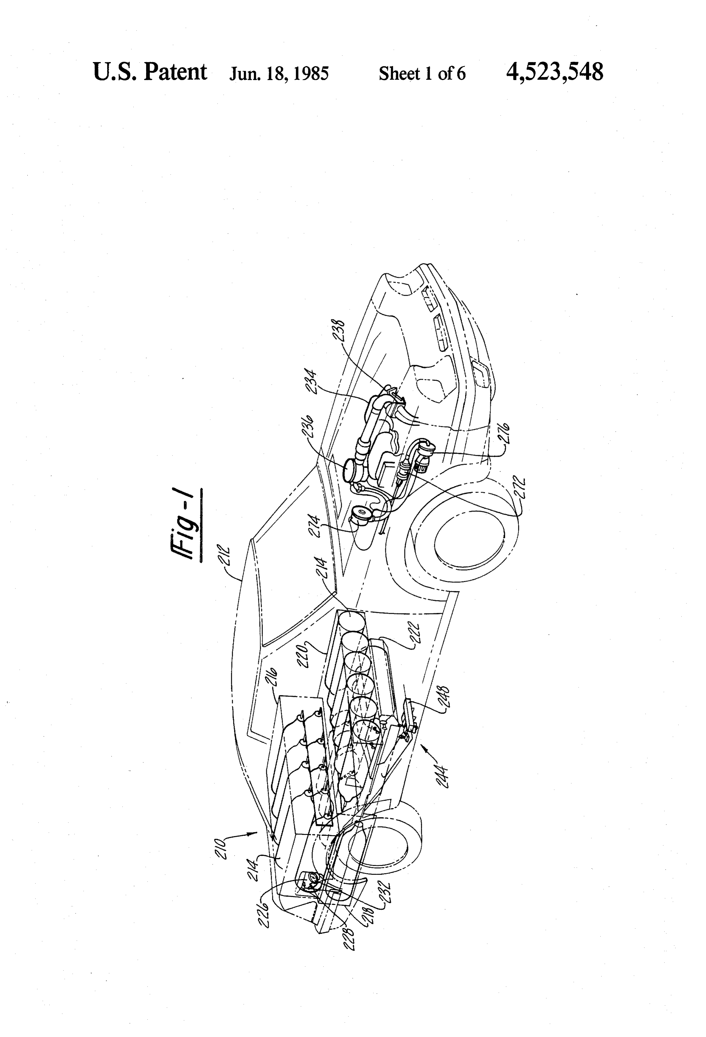
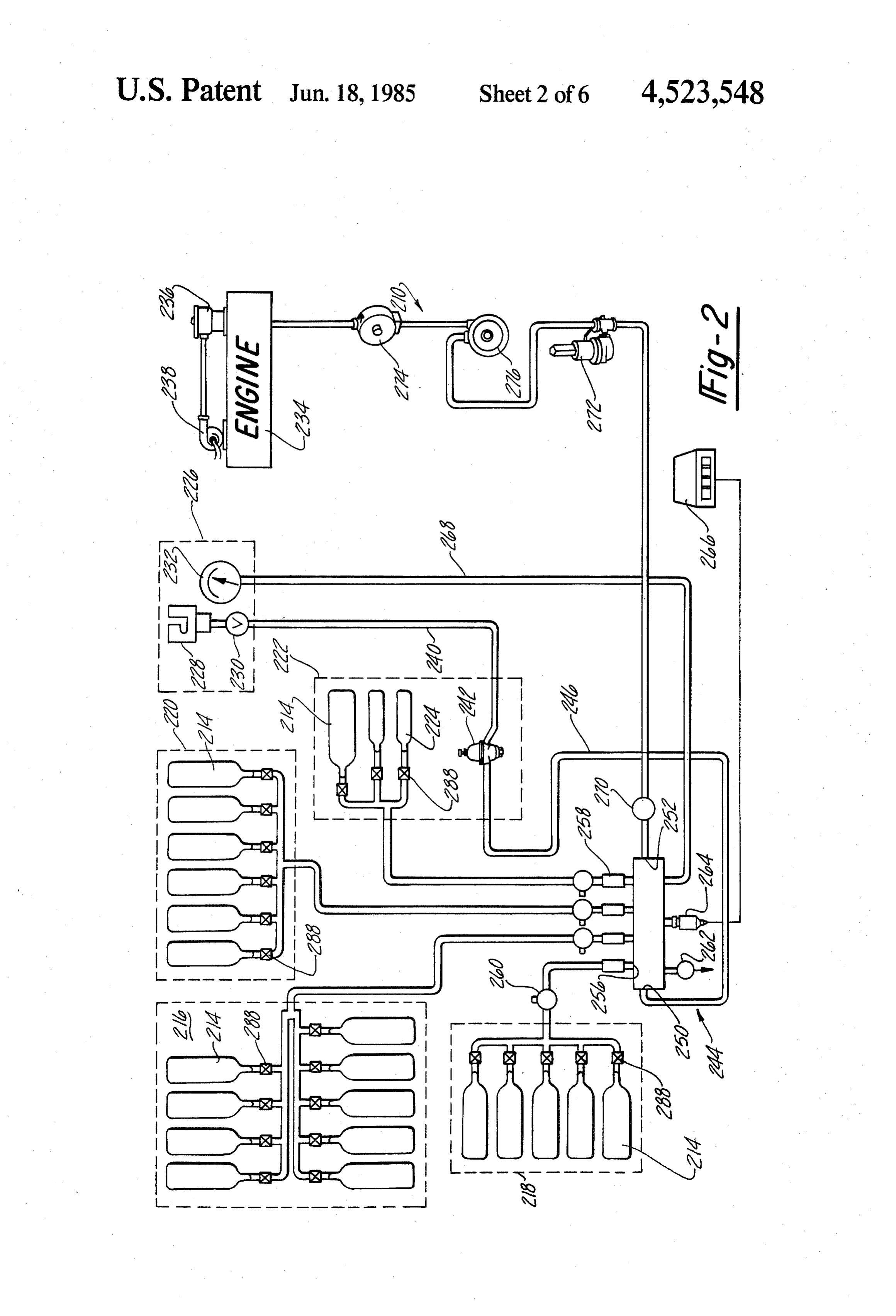
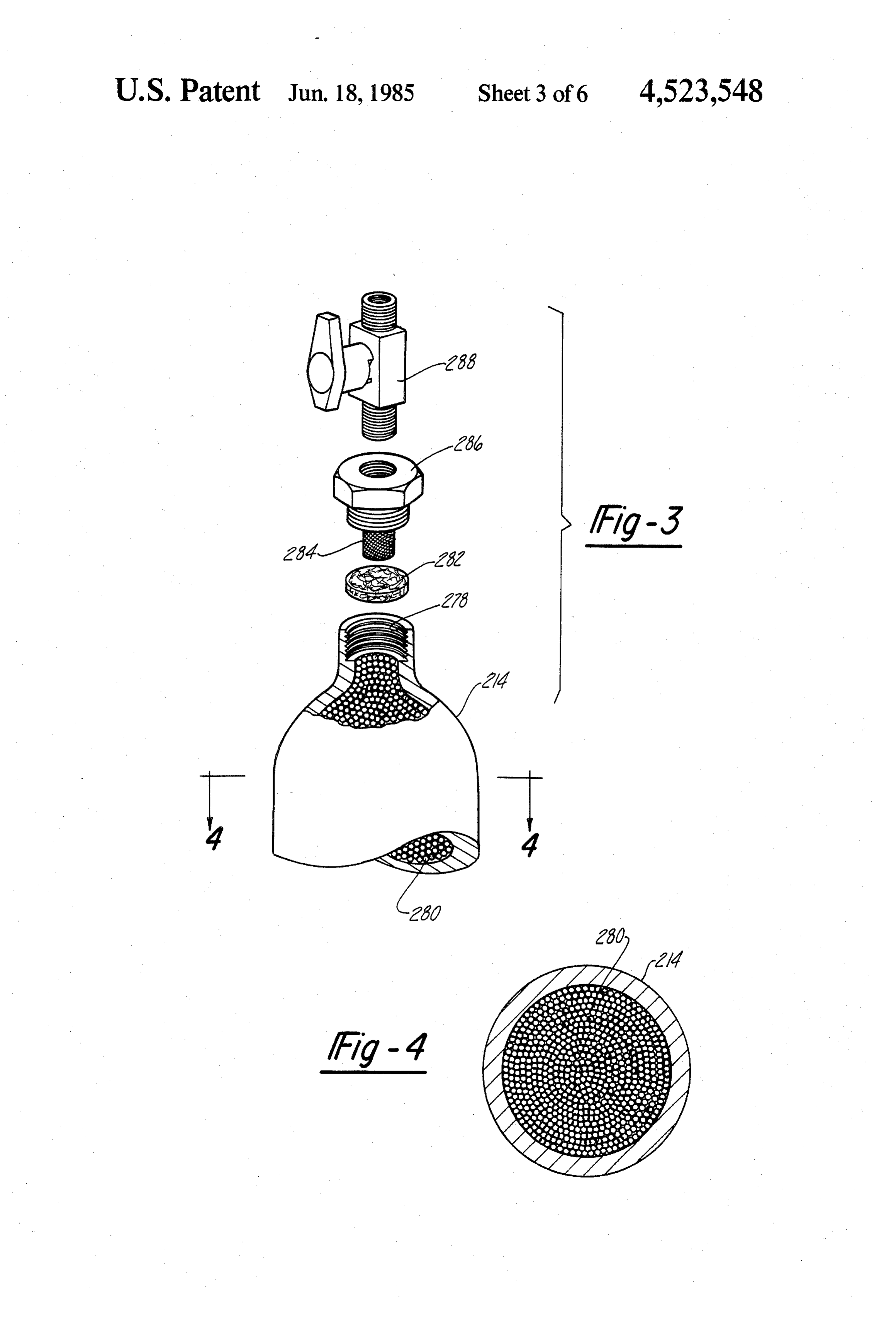
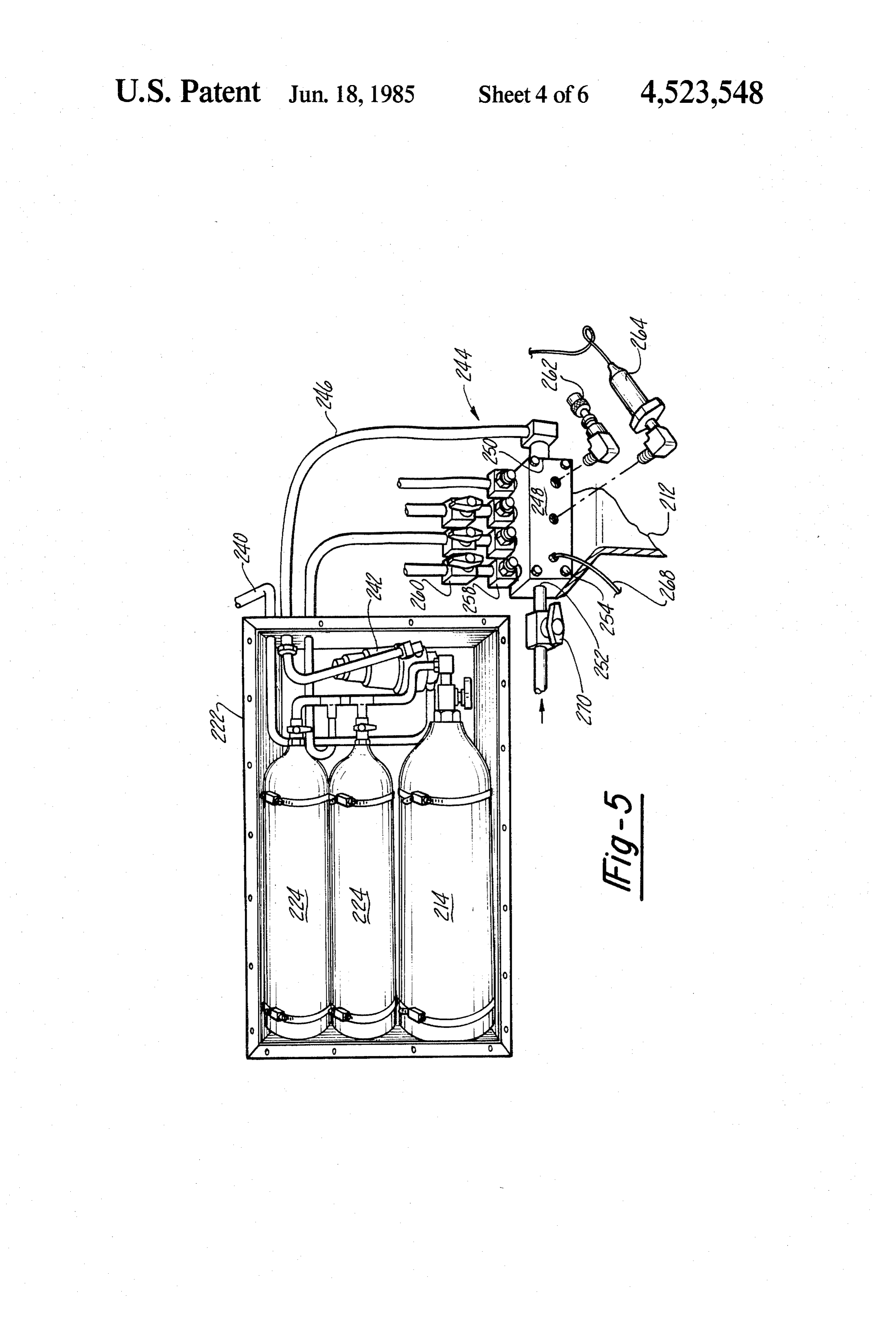
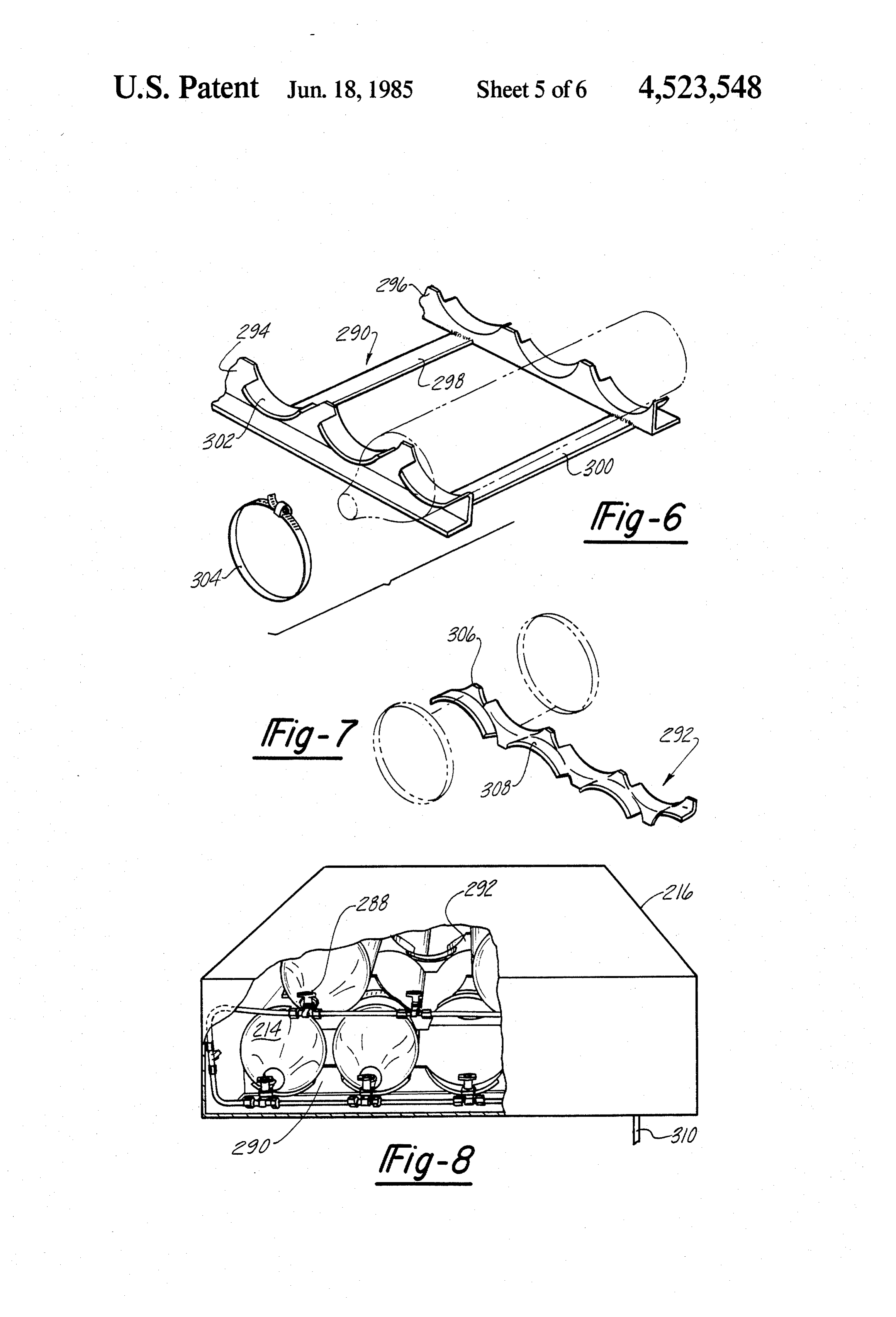
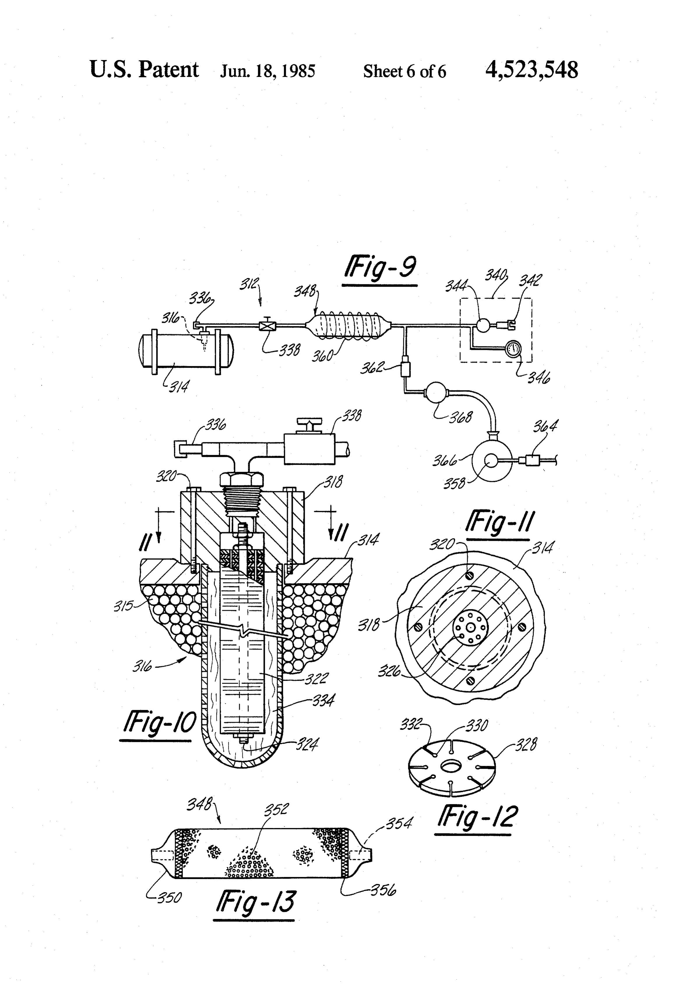
FIG. 1 is an overall perspective view of an exemplary 216 which houses nine cylinders, a chamber 218 which low pressure gaseous hydrocarbon fuel storage system houses five cylinders, a chamber 220 which houses six and power plant according to the present invention. cylinders, and a chamber 222 which houses three cylin FIG. 2 is a schematic view of the low pressure gase ders. These chambers are shown in phantom in FIG. 2. Ous hydrocarbon fuel storage system and power plant It should also be noted that the chamber 222 includes shown in FIG. 1. 10 two cylinders 224 which are smaller than the cylinders FIG. 3 is an exploded assembly view of one of the 214 which are used throughout the rest of the storage gaseous hydrocarbon fuel storage cylinders shown in system. m FIG. I. Accordingly, the storage system portion of the power FIG. 4 is a cross-sectional view of the cylinder shown plant 210 includes a total of twenty-three cylinders to in FIG. 2, taken along lines 3-3. 5 store the natural gas or other gaseous hydrocarbon fuel. FIG. 5 is a perspective view of a portion of the low These twenty-three storage cylinders provide for a total pressure gaseous hydrocarbon fuel storage system and gas storage capability of approximately 8.1 cubic feet power plant shown in FIG. 1, particularly illustrating (0.23 cubic meters). In the particular embodiment the manifold means according to the present invention. shown in FIGS. 1 and 2, the cylinders 214 and 224 are FIG, 6 is a perspective view of a first cradle used to 20 conventional fire-extinguisher type cylinders. The par mount the stored cylinders in the vehicle. ticular number and configuration of the cylinders 214 FIG. 7 is a perspective view of a second cradle used and 224 were chosen to conform to the space available to mount the stored cylinders in the vehicle. in the vehicle 212, and thereby avoid any significant FIG. 8 is a perspective cut-away view of a a double modifications to the structure of the vehicle 212 other row chamber in accordance with the present invention. 25 than the removal of the gasolene tank which was origi FIG. 9 is a schematic view of a second low pressure nally equipped to the vehicle 212.
gaseous hydrocarbon fuel storage system and power It should be appreciated that the principles of the plant in accordance with the present invention. present invention are not in any way limited to the FIG, 10 is a cross-sectional view of a portion of the particular number and configuration of cylinders shown Storage system shown in FIG. 9, particularly illustrating 30 in FIGS. 1 and 2. Indeed, the twenty-three cylinders the in-line filter to the storage tanks. may be replaced by a single storage vessel in the appro FIG. 11 is a cross-sectional view of the filter assembly priate application. Accordingly, it should be under shown in FIG. 10 taken along lines 11-11. stood that a variety of suitable storage vessel types, FIG. 12 is a perspective view of one of the filter discs shapes and sizes may be employed in accordance with shown in FIG, 10. 35 the present invention. The only essential requirement of FIG. 13 is a cross-sectional view of the adsorptive such storage vessels is that they are capable of being filter shown in FIG. 9. pressurized to the maximum pressure limits at which the storage system operates.
DETAILED DESCRIPTION OF THE The power plant 210 also includes a fuel port 226 PREFERRED EMBODIMENTS 40 which is located on the vehicle in the place normally Referring to FIG. 1, an overall perspective view of a used to supply gasolene to the vehicle. The fuel port 226 low-pressure gaseous hydrocarbon fuel storage system comprises a quick connector assembly 228, a check and power plant 210 according to the present invention valve 230, and a pressure gauge 232. The quick connec is shown. The power plant 210 represents an actually tor assembly 228 is used to provide a fluid communica constructed embodiment of the present invention, and 45 tion link to a stationary source of a gaseous hydrocar FIG. 1 shows the physical locations of the various com bon fuel from which the cylinders 214 and 224 may be ponents of the power plant 210 in conjunction with a charged or filled with this fuel.
vehicle 212 (shown in phantom) which was actually One such stationary source of a gaseous hydrocarbon utilized to demonstrate the principles of the present fuel is described in a copending application assigned to invention. In the actually constructed embodiment, 50 the assignee of the present invention, entitled "Gaseous vehicle 212 is a 1983 Ford “EXP' model automobile. Fuel Refueling Apparatus', filed of even date with the However, it should be appreciated that the principles of present application. This copending application dis the present invention are not limited to the embodiment closes a stationary apparatus for supplying fuel to gase shown in FIG. 1, but are equally applicable to other ous fuel consuming devices, such as the vehicle 212. embodiments of gaseous hydrocarbon fuel storage sys 55 This refueling apparatus is adapted to compress or pres tems and power plants, as will become apparent from surize the gaseous fuel to a range of approximately 100 the description below. psig (689 kPa) to approximately 400 psig (2760 kPa). Referring to FIG. 2, a schematic diagram of the Accordingly, this refueling apparatus represents a low power plant 210 is shown. Since some of the compo pressure stationary source of the gaseous hydrocarbon nents of the power plant 210 may be best seen with 60 fuel. Such a re-fueling apparatus and the exemplary reference to FIG. 2, both FIGS. 1 and 2 will be jointly vehicle herein are also disclosed in a copending applica used to describe the overall structure and operation of tion, entitled “GASEOUS HYDROCARBON FUEL the power plant. The power plant 210 includes four STORAGE SYSTEM AND POWER PLANT FOR distinct sets of cylinders 214 which are used to store a VEHICLES AND ASSOCIATED REFUELING self-contained supply of the gaseous hydrocarbon fuel 65 APPARATUS", filed of even date with the present for the vehicle 212. While it is preferred that natural gas application and assigned to the same assignee of the be used for the gaseous hydrocarbon fuel, other gaseous present invention. Both of these patent applications are hydrocarbon fuels may also be utilized, such as propane, hereby incorporated by reference.
Page 12
One of the advantages of the present invention is that be appreciated by those skilled in the art, each incre the storage system may be charged from either a low ment in the compression ratio generally provides for a pressure stationary source of the fuel or a high-pressure 3% improvement in thermodynamic efficiency for each source of the fuel. In the particular embodiment illus incremental increase in compression ratio. This increase trated in FIGS. 1 and 2, gaseous hydrocarbon fuel may 5 in the compression ratio was achieved by installing be provided to the storage system at pressures up to longer pistons in the engine and appropriately milling 3000 psi (20.7 MPA). Such a high pressure stationary the engine head to decrease the available volume in the source of gaseous hydrocarbon fuel may be provided engine cylinders. It should also be noted that the engine for example by a fill station used in fleet operations. timing was appropriately advanced to account for the The check valve 230 is used to permit flow of the O difference in the flame speed of gasoline and natural gas. gaseous hydrocarbon fuel from the stationary source of It should be further noted that the conversion of the the fuel to the storage cylinders 214 and 224 through the vehicle 212 to a natural gas powered vehicle permitted quick connector assembly 228, and also to prevent the the catalytic converter and the other standard pollution flow of the gaseous hydrocarbon fuel from the storage control equipment to be removed from the vehicle. The cylinders out through the connector assembly. As with 15 elimination of this equipment was in recognition of the the quick connector assembly 228, the check valve 230 fact that natural gas is a much more cleaner burning fuel may be comprised of any conventional and commer than gasoline, (i.e fewer objectional emissions). cially available device suitable for the operation de Turning again to the means for conveying the gase scribed above. For example, the check valve 230 in one ous hydrocarbon fuel to the storage cylinders 214 and embodiment according to the present invention com 20 224 and from these cylinders to the carburetor 236 of prises a model B-8CPA2-350 check valve available the engine 234, a high pressure conduit 240 is provided from the Nupro Company, Willoughby, Ohio. to receive the gaseous hydrocarbon fuel supplied at the The pressure gauge 232 is used to provide a visual fuel port 226. The high pressure conduit 240 is prefera indication of the pressure in the storage cylinders 214 bly made from stainless steel and capable of withstand and 224. As will be appreciated by those skilled in the 25 ing pressures up to 3000 psi (20.7 MPa). A high pressure art, the pressure gauge 232 will be particularly useful regulator 242 is mounted in the chamber 222 and con when the storage system is being charged with the nected to the high pressure conduit 240 for defining the gaseous hydrocarbon fuel, as the pressure reading will maximum pressure at which the gaseous hydrocarbon be indicative of the amount of gas stored. fuel is stored in the cylinders 214 and 224. Specifically, The above described fuel port 226 forms part of the 30 the high pressure regulator 242 operates to reduce pres conveying means according to the present invention sures from as high as 3000 psi (20.7 MPa) to a maximum which is used to convey the gaseous hydrocarbon fuel pressure of 300 psig (2070 kPa). Accordingly, the maxi to the storage cylinders 214 and 224 from the stationary mum pressure at which gaseous hydrocarbon fuel can source of the fuel and for conveying the fuel stored in be stored in the cylinders 214 and 224 is approximately these cylinders to the prime nover of the vehicle 212. 35 300 psig (2070 kPa).
In the embodiment shown in FIGS. 1 and 2, this prime In the actually constructed embodiment of the pres mover is generally comprised of an internal combustion ent invention shown in FIGS. 1 and 2, the high pressure engine 234. However, it should be appreciated that the regulator 242 is comprised of a model 1301G high pres principles of the present invention are not limited to any sure regulator available from Fisher Controls Com particular type of prime mover, providing that the 40 pany, Marshall Town, Iowa. However, as with all of prime mover has means for combining the gaseous hy the various components to the power plant 210, the drocarbon fuel with air to produce the mechanical en principles of the present invention are not limited to the ergy therefrom necessary to move the vehicle 212. In particular high pressure regulator utilized in the actu the embodiment shown in FIGS. 1 and 2, this combin ally constructed embodiment of FIGS. 1 and 2. Thus, it ing means is comprised of a carburetor 236 and a turbo 45 should be appreciated that other pressure regulating charger 238. The carburetor 236 is specifically designed devices may be employed to provide suitable maximum to be operable with gaseous hydrocarbon fuels such as pressure limits in the appropriate applications. For ex natural gas. In one form of the present invention, the ample, while it is preferred that the maximum pressure carburetor 236 is a model CA100-8 carburetor which is at which gaseous hydrocarbon fuel is stored to be available from Impco Carburetion, Inc., Cerritos, Calif. 50 within the range of approximately 100 psig (689 kPa) to Additionally, in this actually constructed embodiment approximately 400 psig (2760 kPa), higher or lower of the present invention, the turbo charger 238 is a maximum pressure limits may also be employed. How model RHB5 turbo charger available from Warner-Ishi, ever, it should be understood that one of the principle Decatur, Ill. As will be appreciated by those skilled in advantages of the present invention is that the power the art, the turbo charger 238 is used to increase the 55 plant 210 is capable of storing reasonable amounts of the pressure of the intake air to the engine, and therefore gaseous hydrocarbon fuel at relatively low pressures, provide for additional horsepower. i.e. pressures below approximately 500 psig (3450 kPa). Since the power plant 210 is intended to operate Indeed, with a 300 psig (2070 kPa) pressure limit the solely upon a gaseous hydrocarbon fuel rather than range of the actually constructed embodiment accord gasoline, certain advantageous modifications to the 60 ing to the present invention has been shown to be ap engine 234 were made in the actually constructed em proximately 100-110 miles (161-177 km) in tests where bodiment of FIG. 1. These modifications were designed the vehicle 210 was travelling at a constant velocity of to optimize the performance of the engine 234 in con 45 miles per hour (72 km per hour). junction with the use of natural gas as the fuel for the One of the important components of the conveying engine 234. Firstly, the compression ratio to this stan 65 means is a manifold assembly 244 which is used to dis dard equipment engine for the vehicle 212 was in tribute the gaseous hydrocarbon fuel received from the creased from 8:1 to 13.6:1 in order to take advantage of Stationary Source to each of the cylinders 214 and 224. the relatively high octane rating of natural gas. As will The manifold assembly 224 is also used to collect the
Page 13
gaseous hydrocarbon fuel stored in the cylinders 214 an electrical signal output to a digital display 266 lo and 224 in order to convey this fuel to the carburetor cated in the passenger compartment of the vehicle 212, 236 of the engine 234. The manifold assembly 244 is which is used to provide a visual indication of the pres connected to the high pressure regulator 242 via a low Sure sensed by the transducer. Accordingly, it will be pressure conduit 246. It should be noted that as a result appreciated that the digital display 266 serves as a fuel of the low pressure operation it is preferred that the gauge for the operator of the vehicle 212. It should also conduit 246 as well as the other remaining conduits in be noted that the pressure gauge 232, described above, the power plant 210 be made from copper. However, of is also connected to the manifold block 248 via a con course, other suitable materials may also be employed duit 268.
to construct these conduits, such as coated aluminum Finally, the manifold assembly 244 also includes a and braided steel hose. manual valve 270 for controlling the flow of the gaseous The manifold assembly 244 includes a manifold block hydrocarbon fuel from the outlet port 252 of the mani 248, which may best be seen with reference to FIG. 5. fold block 248 to the carburetor 236 of the engine 234. The manifold block 248 is preferably made out of alumi Thus, the valve 270 provides a means for manually num, and includes an inlet port 250 for receiving the 5 turning off all flow of the gaseous hydrocarbon fuel gaseous hydrocarbon fuel from the stationary source from the cylinders 214 and 224 to the engine 234, such and an outlet port 252 for conveying the gaseous hydro as for maintenance of the power plant 210 and the like. carbon fuel stored in the cylinders 214 and 224 to the In the actually constructed embodiment of FIG. 1, the carburetor 236 of the engine 234. A plurality of bolts valve 270 is comprised of a Nupro B8P6T series valve. 254 are provided to mount the manifold block 248 to the 20 The power plant 210 also includes means for control vehicle 212. The manifold block 248 also includes a ling the flow of the gaseous hydrocarbon fuel from the bi-directional port for conveying the gaseous hydrocar storage system to the carburetor 236 of the engine 234. bon fuel to and from each of the chambers 216-222. This controlling means is generally comprised of a pair Thus, for example, the manifold block 248 includes a of regulators 272-274, and switch 276. The regulators bi-directional port 256 for conveying the gaseous hy 25 272 and 274 are used to reduce the pressure of the gase drocarbon fuel to and from the cylinders 214 contained ous hydrocarbon fuel conveyed to the carburetor 236. in the chamber 218. In the actually constructed embodiment of FIG. 1, the The manifold assembly 244 also includes a filter ele regulator 272 is comprised of a Fisher 620 series regula ment 258 connected to each of the bi-directional ports tor which reduces the pressure from 300 psig (2070 kPa) of the manifold blocks 248 for filtering the flow of the 30 to 100 psig (689 kPa), and the regulator 274 is comprised gaseous hydrocarbon fuel to each of the chambers of an Impco model PEV regulator which reduces the 216-222. In the actually constructed embodiment of pressure from 100 psig (689 kPa) to approximately at FIG. 1, these filter elements 258 each comprise a TF mospheric pressure. The switch 276 is used for selec series Nupro filter. However, it should be appreciated tively permitting flow of the gaseous hydrocarbon fuel that any other filter means known in the art that is suit 35 from the storage system to the carburetor 234, and is able for substantially preventing the introduction of adapted to be responsive to the closing of the ignition particles or other impurities into the cylinders 214 and switch or the energization of the engine 234. In the 224 may be utilized. Thus, for example, fiberous-type actually constructed embodiment of FIG. 1, the switch filters, screen-mesh filters, and filters of sintered con 276 is comprised of an Impco series VFF-30 fuel lock struction may be suitably employed. 40 filter. Again, with regard to the switch 276, as well as to Also interposed between the manifold block 248 and all the other components of the power plant 210, the the chambers 218-222 is a three-way valve 260. These principles of the present invention are not limited to the three-way valves 260 are used for individually control specific actually constructed embodiment of FIG. 1, ling the flow of the gaseous hydrocarbon fuel to and and it should be understood that other suitable compo from each of the chambers 216-222. Thus, for example, 45 nents may be employed equally as well. the three-way valve 260 interposed between the cham Referring to FIGS. 3 and 4, the specific construction ber 218 and the manifold block 248 may be manually of the storage cylinders 214 and 224 will now be de closed to prevent the flow of any gaseous hydrocarbon scribed. Each of the storage cylinders includes an in fuel to or from the cylinders 214 contained in this cham let/outlet port 278 for conveying the gaseous hydrocar ber. In the actually constructed embodiment of FIG. 1, 50 bon fuel to and from the cylinders. Importantly, each of these three-way valves 260 are also used to permit gas the storage cylinders 214 and 224 contain a predeter samples to be obtained from each of the chambers mined sorbent material 280 for reducing the pressure at 216-222, which the gaseous hydrocarbon fuel is stored within the The manifold assembly 244 also includes a pressure cylinders. As referred to herein, the terms "sorbent' or relief valve 262 which is used to insure that the pressure 55 "sorptive' are intended to refer to "adsorbents", "ab in the storage cylinders 214 and 224 does not exceed a sorbents' or both. The absorbent material may com predetermined pressure limit. Preferably, this predeter prise any of a number of adsorbents or molecular sieves, mined pressure limit should exceed the maximum pres such as activated carbon, zeolite compounds, various sure range of the storage system by a predetermined clays, or silica gels, for example. Such adsorbent materi amount, such as 25 psig (172 kPa) to 150 psig (1034 60 als may be in the form of pellets, spheres, granulated kPa). In the actually constructed embodiment of FIG. particles, or other suitable forms whereby the surface 1, the pressure relief valve 262 is adapted to open at 425 area of the adsorbent material is optimized in order to psig (2930 kPa). maximize the amount of gaseous fuel adsorbed on the The manifold assembly 244 also includes a transducer surface thereof. The present invention also contem 264 for sensing the pressure within the cylinders 214 65 plates the use of liquid absorbents, such as a liquid coat and 224. The transducer 264 may be any suitable pres ing on an adsorbent material.
sure transducer such as a Kulite type IPTE-1000 pres Although Columbia grade 9LXC activated carbon sure transducer. The pressure transducer 264 generates pellets were used as the sorbent material 280 in the
Page 14
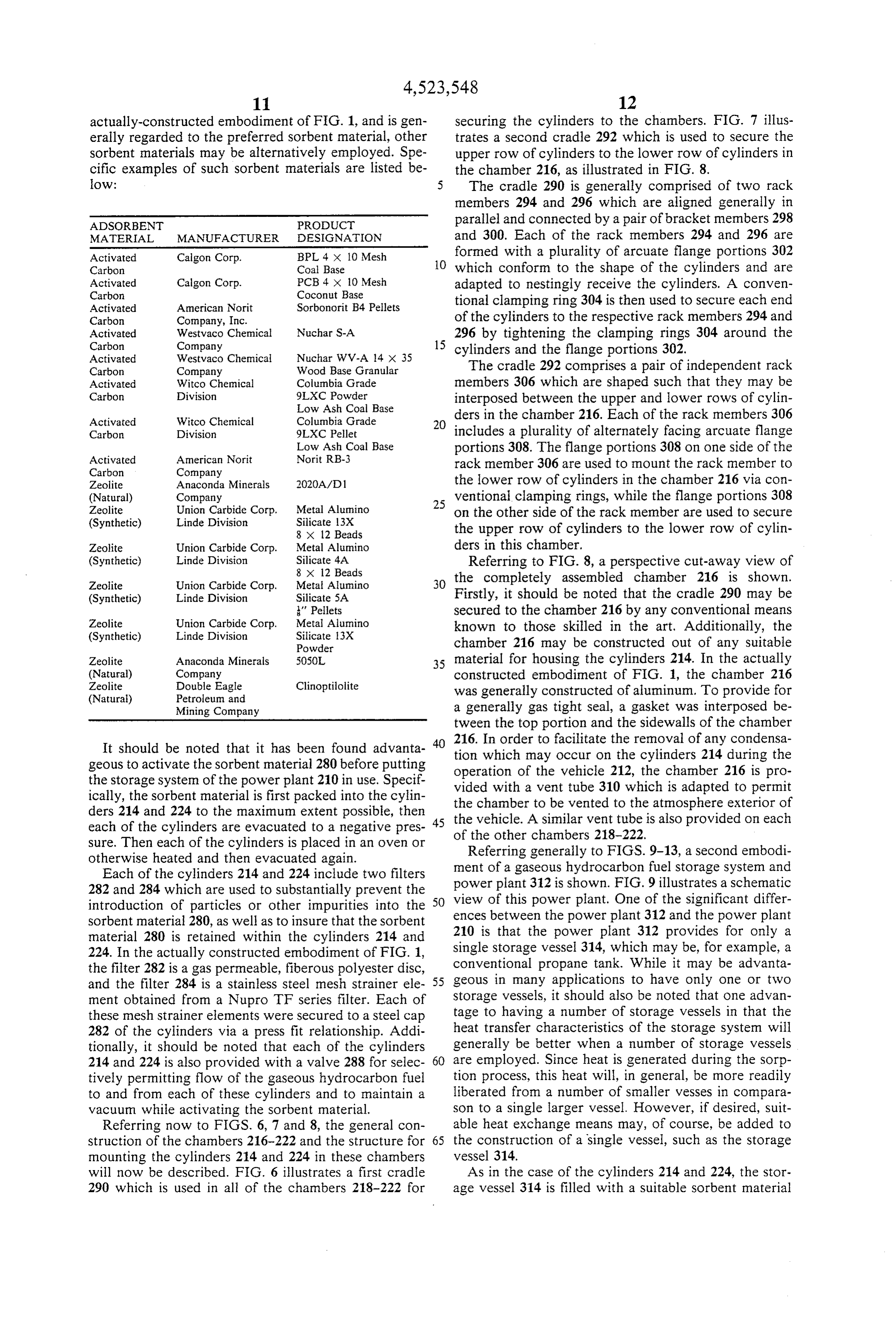
actually-constructed embodiment of FIG. 1, and is gen securing the cylinders to the chambers. FIG. 7 illus erally regarded to the preferred sorbent material, other trates a second cradle 292 which is used to Secure the sorbent materials may be alternatively employed. Spe upper row of cylinders to the lower row of cylinders in cific examples of such sorbent materials are listed be the chamber 216, as illustrated in FIG. 8. ow: The cradle 290 is generally comprised of two rack members 294 and 296 which are aligned generally in
ADSORBENT PRODUCT parallel and connected by a pair of bracket members 298 MATERIAL MANUFACTURER DESIGNATION and 300. Each of the rack members 294 and 296 are Activated Calgon Corp. BPL 4 x 10 Mesh formed with a plurality of arcuate flange portions 302 Carbon Coal Base O which conform to the shape of the cylinders and are Activated
Carbon
Coconut Base adapted to nestingly receive the cylinders. A conven
Activated American Norit Sorbonorit B4 Pelets tional clamping ring 304 is then used to secure each end Carbon Company, Inc. of the cylinders to the respective rack members 294 and Activated Westvaco Chemical Nuchar S-A 296 by tightening the clamping rings 304 around the Carbon Company 15 cylinders and the flange portions 302. Activated Westvaco Chemical Nuchar WW-A 4 x 35
Carbon Company Wood Base Granular The cradle 292 comprises a pair of independent rack Activated Witco Chemical Columbia Grade members 306 which are shaped such that they may be
Low Ash Coal Base interposed between the upper and lower rows of cylin
Activated Witco Chemical Columbia Grade 2O ders in the chamber 216. Each of the rack members 306 Carbon Division 9LXC Pelet includes a plurality of alternately facing arcuate flange Activated American Norit
Low Ash Coal Base
Norit RB-3 portions 308. The flange portions 308 on one side of the
Carbon Company rack member 306 are used to mount the rack member to
Zeolite Anaconda Minerals 2020A/D1 the lower row of cylinders in the chamber 216 via con (Natural) Company ventional clamping rings, while the flange portions 308 Zeolite Union Carbide Corp. Metal Alumino 25 on the other side of the rack member are used to Secure (Synthetic) Linde Division Silicate 13X 8 X 2 Beads the upper row of cylinders to the lower row of cylin
Zeolite Union Carbide Corp. Metal Alumino ders in this chamber.
(Synthetic) Linde Division Silicate 4A 8 x 12 Beads
Referring to FIG. 8, a perspective cut-away view of
Zeolite Union Carbide Corp. Metal Alumino 30 the completely assembled chamber 216 is shown. (Synthetic) Linde Division Silicate 5A Firstly, it should be noted that the cradle 290 may be " Pellets secured to the chamber 216 by any conventional means
Zeolite Union Carbide Corp. Metal Alumino known to those skilled in the art. Additionally, the (Synthetic) Linde Division Silicate E3X
Powder chamber 216 may be constructed out of any Suitable
Zeolite Anaconda Minerals 5050L 35 material for housing the cylinders 214. In the actually (Natural) Company constructed embodiment of FIG. 1, the chamber 216 Zeolite Double Eagle Clinoptilolite was generally constructed of aluminum. To provide for (Natural) Petroleum and
Mining Company a generally gas tight seal, a gasket was interposed be tween the top portion and the sidewalls of the chamber
It should be noted that it has been found advanta 40 216.
tion
In order to facilitate the removal of any condensa which may occur on the cylinders 214 during the geous to activate the sorbent material 280 before putting operation of the vehicle 212, the chamber 216 is pro the storage system of the power plant 210 in use. Specif vided with a vent tube 310 which is adapted to permit ically, the sorbent material is first packed into the cylin the chamber to be vented to the atmosphere exterior of ders 214 and 224 to the maximum extent possible, then 45 the vehicle. A similar vent tube is also provided on each each of the cylinders are evacuated to a negative pres sure. Then each of the cylinders is placed in an oven or ofReferring the other chambers 218-222.
generally to FIGS. 9-13, a second embodi otherwise heated and then evacuated again. ment of a gaseous hydrocarbon fuel storage system and Each of the cylinders 214 and 224 include two filters power plant 312 is shown. FIG. 9 illustrates a schematic 282 and 284 which are used to substantially prevent the introduction of particles or other impurities into the 50 view of this power plant. One of the significant differ ences between the power plant 312 and the power plant sorbent material 280, as well as to insure that the sorbent material 280 is retained within the cylinders 214 and 210 is that the power plant 312 provides for only a 224. In the actually constructed embodiment of FIG. 1, single storage vessel 314, which may be, for example, a the filter 282 is a gas permeable, fiberous polyester disc, conventional propane tank. While it may be advanta and the filter 284 is a stainless steel mesh strainer ele- 55 geous in many applications to have only one or two ment obtained from a Nupro TF series filter. Each of storage vessels, it should also be noted that one advan these mesh strainer elements were secured to a steel cap tage to having a number of storage vessels in that the 282 of the cylinders via a press fit relationship. Addi heat transfer characteristics of the storage system will tionally, it should be noted that each of the cylinders generally be better when a number of storage vessels 214 and 224 is also provided with a valve 288 for selec 60 are employed. Since heat is generated during the sorp tively permitting flow of the gaseous hydrocarbon fuel tion process, this heat will, in general, be more readily to and from each of these cylinders and to maintain a liberated from a number of smaller vesses in compara vacuum while activating the sorbent material. son to a single larger vessel. However, if desired, suit Referring now to FIGS. 6, 7 and 8, the general con able heat exchange means may, of course, be added to struction of the chambers 216-222 and the structure for 65 the construction of a single vessel, Such as the storage mounting the cylinders 214 and 224 in these chambers vessel 314.
will now be described. FIG. 6 illustrates a first cradle As in the case of the cylinders 214 and 224, the stor 290 which is used in all of the chambers 218-222 for age vessel 314 is filled with a suitable sorbent material
Page 15
315 for reducing the pressure at which the gaseous It should be noted that the sorptive filter 348 is associ hydrocarbon fuel is stored. The storage vessel 314 is ated with the conveying means of the power plant 312 also provided with a filter assembly 316 which may best such that the gaseous hydrocarbon fuel supplied by a be seen with reference to FIG. 10. The filter assembly stationary source thereof must first pass through the 316 includes an aluminum block 318 which is secured to sorptive filter before being stored in the storage vessel the storage vessel 314 via a plurality of bolts 320. A 314. Likewise, before the stored gaseous hydrocarbon conventional 80 micron filter 322 is secured to the block fuel can be conveyed to a carburetor 358 of the power 318 via a bolt 324. The block 318 is also formed with plant 312, this fuel must again pass through the sorptive eight circumferentially spaced passageways 326 which filter 348. During the charging of the stored vessel 314, provide a fluid communication link between the filter 10 the sorptive filter 348 adsorptively and/or absorptively 322 and the conduit means used to convey the gaseous removes predetermined constituents of the gaseous hydrocarbon fuel to and from the storage vessel 314. hydrocarbon fuel, as well as any odorent previously These passageways 326 may best be seen with reference introduced to the fuel, before the gaseous hydrocarbon to FIG. 11 which is a cross-sectional view of the filter fuel is conveyed to the stored cylinder 314. These pre assembly 316 taken along lines 11-11 of FIG. 10. 15 determined constituents include, for example, oil, water The filter 322 is comprised of a plurality of adjacently vapor, and so-called "heavy end' constituents of the disposed copper plates or discs 328. A perspective view fuel. Generally speaking, such heavy end constituents of one of these copper plates 228 is shown in FIG. 12. include propane and other constituents that are heavier Each of these copper plates 328 includes a total of eight than methane. The purpose of removing such heavy end circumferentially spaced openings 330 and a slot 332 20 constituents is to maximize the capability of the storage extending radially outwardly from these openings to vessel 314 to sorptively store the lighter hydrocarbons, provide an outlet for the filter having a magnitude of 80 such as methane for example. It is also important to note microns. As will be appreciated by those skilled in the that the sorptive filter 348 also operates to prevent the art, each of the copper plates 328 are aligned such that accummulation over time of any unwanted fuel constit the openings 330 form vertical passageways along the 25 uents in the storage vessel 314.
length of the filter 322. The filter assembly 316 also When the engine for the power plant 312 is energized includes a gas permeable, fiberous filter which is prefer and enabled to consume the gaseous hydrocarbon fuel ably, although not necessarily, made from a suitable stored in the storage vessel 314, the sorptive filter 348 polyester material. This fiberous filter element 334 is operates to desorptively re-introduce the removed con interposed between the filter 322 and the sorbent mate 30 stituents and odorent to the flow of the gaseous hydro rial 315. carbon fuel from the stored cylinder 314 to the carbure As may be seen in both FIGS. 9 and 10, the storage tor 358 of the engine. Accordingly, it should be appreci vessel 314 is also provided with a relief valve 336 and a ated that the sorptive filter 348 is self-cleaning during manual shut-off valve 338. The relief valve 336 operates each charge and discharge cycle of the storage system. to insure that the pressure in the storage vessel 314 does 35 In order to assist the desorption of the undesirable not exceed the maximum pressure at which the power constituents from the sorbent material 352 contained in plant 312 is intended to operate. the filter 348, means for increasing the temperature of The power plant 312 also includes a fuel port 340 the sorptive filter 348 may also be provided in the ap which generally comprises a quick connector assembly propriate application. Preferably, this temperature in 342, a check valve 344 and a pressure gauge 346. Inter 40 creasing means is associated with the engine of the posed between the fuel port 340 and the storage vessel power plant 312 so that the heat generated by the opera 314 is an sorptive filter 348 which forms an important tion of the engine is utilized by the temperature increas part of the present invention. A cross-sectional view of ing means. One form of a suitable temperature increas the sorptive filter is shown in FIG. 13. The sorptive ing means is shown in FIG. 9 to be a conduit 360 which filter 348 is comprised of a vessel 350 which contains a 45 is wrapped around the sorptive filter 348. This conduit predetermined sorbent material 352 for filtering the could be connected, for example, to either the engine flow of the gaseous hydrocarbon fuel to the storage cooling system or to the engine exhaust system in order vessel 314. The vessel 350 may be any shape or con to utilize at least a portion of the waste heat generated struction which is capable of withstanding the maxi by the engine. Additionally, it may be advantageous in mum pressure at which the power plant 312 is intended 50 some applications to simply locate the sorptive filter in to operate. However, it is generally preferred that the relatively close proximity to the engine in order to size of filter vessel 350 be related to the size of the stor utilize the heat radiated by the engine. age vessel 314. Specifically, it has been found advanta Another significant difference between the power geous to provide at least 0.0052 cubic feet (0.147 cubic plant 210 of FIG. 1 and the power plant 312 of FIG. 9, millimeters) of filter capacity to each cubic feet (0.028 55 is that the power plant 312 is adapted to operate as a cubic meters) of storage capacity. With regard to the dual fuel system. This dual fuel operation is controlled sorbent material 352, it is preferred that this sorbent by a pair of solenoid valves 362 and 364. The solenoid material be comprised of activated carbon. In this re valve 362 is used to control the flow of the gaseous gard, both the sorbent material 352 contained in the hydrocarbon fuel from the storage vessel 314 to an sorptive filter 348 and the sorbent material 315 con 60 air/fuel mixer 366 operatively associated with the car tained in the storage vessel 314 may both be comprised buretor 358. Whereas, the solenoid valve 364 is used to of activated carbon. control the flow of gasolene from a suitable gaseoline The sorptive filter 348 is provided with a filter ele tank (not shown) to the carburetor 358 of the engine. It ment 354 and a gas permeable, fiberous filter element should also be noted that a two-stage regulator 368 is 356 at each end thereof. These two filter elements may 65 interposed between the solenoid valve 362 and the air/f. be similar in construction to either those corresponding uel mixer 366. This regulator 368 is used to reduce the filter elements shown in FIG. 3 or 10, or other suitable pressure of the gaseous hydrocarbon fuel from approxi filter construction. mately 300 psig (2070 kPa) to approximately atmo
Page 16
spheric pressure. The solenoid valves 362 and 364 may 4. The gaseous hydrocarbon fuel powered vehicle be operable in response to one or more Switches con according to claim 3, wherein said storing means also tained in the passenger compartment of the vehicle includes filter associated with each of said vessels, and a which are used to determine which source of fuel Sup valve associated with each of said vessels for selectively ply will be provided to the engine. Accordingly, it 5 permitting flow of said gaseous hydrocarbon fuel to and should be appreciated that if the vehicle operator de from said vessels.
sires gasoline to be supplied to the engine, the Solenoid 5. The gaseous hydrocarbon fuel powered vehicle valve 364 must be opened and the solenoid valve 362 according to claim 4, wherein each of said vessels is a must be closed. Similarly, if the vehicle operator desires light weight cylinder and each of said filters are inter that the gaseous hydrocarbon fuel be supplied to the 10 nally secured to the caps of said cylinders. engine, the solenoid valve 362 must be opened and the 6. The gaseous hydrocarbon fuel powered vehicle solenoid valve 364 must be closed. according to claim 5, wherein said storing means fur It should also be noted that in such a dual fuel power ther includes a gas permeable element interposed be plant, it will be difficult to provide an engine whose tween each of said filters and said sorbent material. performance is optimized for both types of fuel. How 5 7. The gaseous hydrocarbon fuel powered vehicle ever, there are commercially available devices which according to claim 6, wherein each of Said gas permea are capable of automatically adjusting the timing of the ble elements is a fibrous polyester element. engine in response to a switch between the type of fuel 8. The gaseous hydrocarbon fuel powered vehicle being supplied to the engine. according to claim 4, wherein the said plurality of ves The foregoing discussion discloses and describes ex sels are contained in at least one enclosed chamber. emplary embodiments of the present invention. One 9. The gaseous hydrocarbon fuel powered vehicle skilled in the art will readily recognize from such dis according to claim 8, wherein each of Said vessels is a cussion that various changes, modifications and varia tions may be made therein without departing from the lightweight means for cylinder, and said chamber includes cradle securing said cylinders to Said chamber.
spirit and scope of the invention as defined in the fol 25 10. The gaseous hydrocarbon fuel powered vehicle lowing claims. according to claim 9, wherein said cylinders are stacked What is claimed is:
in two rows in said chamber, and said cradle means 1. A low-pressure gaseous hydrocarbon fuel powered includes vehicle comprising: a first set of cradles for securing a bottom row means for storing a self-contained supply of a gaseous 30 of said cylinders to said chamber and a second set of hydrocarbon fuel, said storing means containing a cradles for securing a top row of said cylinders to said predetermined sorbent material for reducing the bottom 11.
row of said cylinders.
The gaseous hydrocarbon fuel powered vehicle pressure at which a given amount of said gaseous hydrocarbon fuel is stored, said gaseous hydrocar according to claim 9, wherein said plurality of cylinders bon fuel being stored at a maximum pressure less 35 includes at least two cylinders, and at least one of said cylinders is contained in a first chamber and at least one than approximately 500 psig (3450 kPa);
a prime mover having means for combining said gase of said cylinders is contained in a second chamber. ous hydrocarbon fuel with air to produce the me 12. The gaseous hydrocarbon fuel powered vehicle chanical energy therefrom necessary to move said according to claim 11, wherein said plurality of cylin vehicle; 40 ders includes at least four cylinders, and at least two of means for conveying said gaseous hydrocarbon fuel said cylinders are contained in said first chamber and at to said storing means from a stationary source of least two of said cylinders are contained in Said Second said gaseous hydrocarbon fuel and for conveying chamber.
said gaseous hydrocarbon fuel from said storing 13. The gaseous hydrocarbon fuel powered vehicle means to said combining means of said prime 45 according to claim 8, wherein said chamber is vented to mover; the atmosphere exterior of said vehicle. sorbent filter means associated with said conveying 14. The gaseous hydrocarbon fuel powered vehicle means for sorptively removing at least a portion according to claim 2, wherein said conveying means of predetermined constituents from the flow of includes manifold means for distributing said gaseous said gaseous hydrocarbon fuel to said storing 50 hydrocarbon fuel received from said stationary source means and for desorptively re-introducing at to each of said plurality of vessels and for collecting said least a portion of said predetermined constituents gaseous hydrocarbon fuel stored in each of said plural to the flow of said gaseous hydrocarbon fuel ity of vessels in order to convey said gaseous hydrocar from said storing means to said combining means bon fuel stored in said plurality of vessels to said com of said prime mover; and 55 bining means of said prime mover.
means associated with said conveying means for con 15. The gaseous hydrocarbon fuel powered vehicle trolling the flow of said gaseous hydrocarbon fuel according to claim 14, wherein said plurality of vessels from said storing means to said combining means of includes at least a first and second set of vessels, where said prime mover. each of said sets of vessels includes at least two vessels. 2. The gaseous hydrocarbon fuel powered vehicle 60 16. The gaseous hydrocarbon fuel powered vehicle according to claim 1, wherein the maximum pressure at according to claim 15, wherein said manifold means which said gaseous hydrocarbon fuel is stored in said includes an inlet port for receiving said gaseous hydro storing means is in the range of approximately 100 psig carbon fuel from said stationary source, a first bi-direc (689 kPa) to approximately 400 psig (2760 kPa). tional port for conveying said gaseous hydrocarbon fuel 3. The gaseous hydrocarbon fuel powered vehicle 65 to and from said first set of vessels, a second bi-direc according to claim 2, wherein said storing means in tional port for conveying said gaseous hydrocarbon fuel cludes a plurality of vessels capable of being pressur to and from said second set of vessels, and an outlet port ized. for conveying said gaseous hydrocarbon fuel stored in
Page 17
said first and second sets of vessels to said combining mover for reducing the pressure of said gaseous hydro means of said prime mover. carbon fuel conveyed to said combining means. 17. The gaseous hydrocarbon fuel powered vehicle 29. The gaseous hydrocarbon fuel powered vehicle according to claim 16, wherein manifold means further according to claim 28, wherein said controlling means includes relief valve means for ensuring that the pres 5 also includes means for selectively permitting flow of sure in said vessels do not exceed a predetermined pres said gaseous hydrocarbon fuel from said storing means S. to said combining means of said prime mover. 18. The gaseous hydrocarbon fuel powered vehicle 30. In a vehicle, a low-pressure gaseous hydrocarbon according to claim 16, wherein said manifold means also fuel power plant, comprising:
includes transducer means for sensing the pressure in 10 means for storing a self-contained supply of a gaseous said vessels. hydrocarbon fuel, said storing means containing a 19. The gaseous hydrocarbon fuel powered vehicle predetermined sorbent material for reducing the according to claim 16, wherein said manifold means pressure at which a given amount of said gaseous includes first valve means for individually controlling hydrocarbon fuel is stored; the flow of said gaseous hydrocarbon fuel to and from 5 a prine mover having means for combining said gase said first and second sets of vessels, and second valve ous hydrocarbon fuel with air to produce the me means for controlling the flow of said gaseous hydro chanical energy therefrom necessary to move said carbon fuel from said outlet port to said combining vehicle;
means of said prime mover. means for conveying said gaseous hydrocarbon fuel 20. The gaseous hydrocarbon fuel powered vehicle 20 to said storing means from a stationary source of according to claim 16, wherein said manifold means said gaseous hydrocarbon fuel and for conveying includes filter element means for filtering the flow of said gaseous hydrocarbon fuel from said storing said gaseous hydrocarbon fuel to said first and second means to said combining means of said prime sets of vessels. nover;
21. The gaseous hydrocarbon fuel powered vehicle 25 means associated with said conveying means for sorp according to claim 2, wherein said conveying means tively filtering the flow of said gaseous hydrocar includes relief valve means for ensuring that the pres bon fuel to said storing means; and sure in said storing means does not exceed a predeter means associated with said conveying means for con mined pressure. trolling said flow of said gaseous hydrocarbon fuel 22. The gaseous hydrocarbon fuel powered vehicle 30 from said storing means to said combining means of according to claim 2, wherein said conveying means said prime mover.
includes transducer means for sensing the pressure in 31. The gaseous hydrocarbon fuel powered vehicle said storing means. according to claim 30, wherein the maximum pressure 23. The gaseous hydrocarbon fuel powered vehicle at which said gaseous hydrocarbon fuel is stored in said according to claim 22, wherein said power plant in 35 storing means is less than approximately 500 psig (3450 cludes display means located in a passenger compart kPa).
ment of said vehicle for providing a visual indication of 32. The gaseous hydrocarbon fuel powered vehicle the pressure sensed by said transducer means, according to claim 31, wherein the maximum pressure 24. The gaseous hydrocarbon fuel powered vehicle at which said gaseous hydrocarbon fuel is stored in said according to claim 2, wherein said conveying means 40 storing means is in the range of approximately 100 psig includes fuel port means for receiving said gaseous (689 kPa) to approximately 400 psig (2760 kPa). hydrocarbon fuel from said stationary source of said 33. The gaseous hydrocarbon fuel powered vehicle gaseous hydrocarbon fuel, said fuel port means includ according to claim 32, wherein said filtering means ing connector means for providing a fluid link to said sorptively removes, at least in part, predetermined con stationary source, and check valve means for permitting 45 stituents of said gaseous hydrocarbon fuel before said flow of said gaseous hydrocarbon fuel from said station gaseous hydrocarbon fuel is conveyed to said storing ary source to said storing means through said connector c2S.
means and preventing flow of said gaseous hydrocarbon 34. The gaseous hydrocarbon fuel powered vehicle fuel from said storing means out through said connector according to claim 33, wherein said filtering means is eaS. 50 associated with said conveying means such that the 25. The gaseous hydrocarbon fuel powered vehicle flow of said gaseous hydrocarbon fuel from said storing according to claim 24, wherein said fuel port means means to said combining means of said prime mover further includes means for providing a visual indication also passes through said filtering means. of the pressure in said storing means. 35. The gaseous hydrocarbon fuel powered vehicle 26. The gaseous hydrocarbon fuel powered vehicle 55 according to claim 34, wherein said filtering means according to claim 24, wherein said conveying means desorptively re-introduces, at least in part, said re further includes high pressure regulator means inter moved predetermined constituents to the flow of said posed between said fuel port means and said storing gaseous hydrocarbon fuel from said storing means to means for defining the maximum pressure at which said said combining means of said prime mover. gaseous hydrocarbon fuel is stored in said storing 60 36. The gaseous hydrocarbon fuel powered vehicle aS. according to claim 35, wherein said power plant in 27. The gaseous hydrocarbon fuel powered vehicle cludes means for increasing the temperature of said according to claim 2, wherein said sorbent material is filtering means when said gaseous hydrocarbon fuel is comprised of activated carbon. conveyed from said storing means to said combining 28. The gaseous hydrocarbon fuel powered vehicle 65 means of said prime mover.
according to claim 2, wherein said controlling means 37. The gaseous hydrocarbon fuel powered vehicle includes regulator means interposed between said stor according to claim 36, wherein said temperature in ing means and said combining means of said prime creasing means is associated with said prime mover
Page 18
such that the heat generated by the operation of said sure vessels in order to convey said gaseous natural prime mover is utilized at least in part by said tempera gas stored in said plurality of pressure vessels to ture increasing means. said carburetion means, said manifold means in 38. The gaseous hydrocarbon fuel powered vehicle cluding an inlet port for receiving said gaseous according to claim 32, wherein said filtering means 5 natural gas from said stationary source, a bi-direc comprises a vessel containing a predetermined sorbent tional port for conveying said gaseous natural gas material. to and from said plurality of pressure vessels and an 39. The gaseous hydrocarbon fuel powered vehicle outlet port for conveying said gaseous natural gas according to claim 38, wherein said predetermined sor in said pressure vessels to said carburetion means; bent material contained in said storing means and said 10 means associated with said conveying means for con predetermined sorbent material contained in said vessel trolling the flow of Said gaseous natural gas from of said filtering means are both comprised of activated said storing means to said carburetion means of said carbon. engine;
40. The gaseous hydrocarbon fuel powered vehicle adsorbent filter means for adsorptively removing at according to claim 33, wherein said predetermined con 15 least a portion of predetermined constitutents of stituents include water vapor, oil, propane, butane and said gaseous natural gas from the flow of said gase hydrocarbons heavier than methane. ous natural gas to said storing means, said adsor 41. A low-pressure natural gas powered vehicle com bent filter means being associated with said con prising: veying means such that the flow of said gaseous means for storing a self-contained supply of gaseous natural gas from said storing means to said carbure natural gas at a maximum pressure less than ap tion means also passes through said adsorbent filter proximately 500 psig (3450 kPa) said storing means means, said adsorbent filtering means desorptively including a plurality of pressure vessels, each of re-introducing at least a portion of said predeter said vessels containing a predetermined adsorbent mined constituents to the flow of said gaseous natu material in order to reduce the pressure at which a 25 ral gas from said storing means to said carburetion given amount of said gaseous natural gas is stored, means; and a plurality of said pressure vessels being contained means for increasing the temperature of said adsor within an enclosed chamber, the interior of said bent filter means when said gaseous natural gas is chamber being vented to the exterior of said vehi conveyed from said storing means to said carbure
tion means.
each of said pressure vessels including an inlet/outlet 42. The natural gas powered vehicle according to port for allowing said gaseous natural gas to flow claim 41, wherein the maximum pressure at which said into and out of said vessel, a filter associated with natural gas is stored in said storing means is in the range each of said vessels for filtering said gaseous natu of approximately ral gas flowing into and out of said vessel, a gas 35 400 100 psig (689 kPa) to approximately permeable element interposed between each of said psig (2760 kPa).
filters and said adsorbent material; 43. The natural gas powered vehicle according to an internal combustion engine having carburetion claim 42, wherein said engine includes turbocharging means for combining said gaseous natural gas with means for increasing the pressure of the intake air to air to produce mechanical energy therefrom in 40 said engine.
order to move said vehicle; 44. The natural gas powered vehicle according to means for conveying said gaseous natural gas to said claim 40, wherein said manifold means includes pres Storing means from a stationary source of said gase sure relief means for substantially ensuring that the Ous natural gas and for conveying said gaseous pressures in said vessels do not exceed a predetermined natural gas from said storing means to said carbure 45 relief pressure.
tion means of said engine; 45. The natural gas powered vehicle according to said conveying means incuding manifold means for claim 40, wherein said temperature increasing means distributing said gaseous natural gas received from includes means for transferring a portion of the heat said stationary source to each of said plurality of generated by said internal combustion engine to said pressure vessels and for collecting said gaseous 50 adsorbent filter means.
natural gas stored in each of said plurality of pres ck ck sk ck ck

Page 19
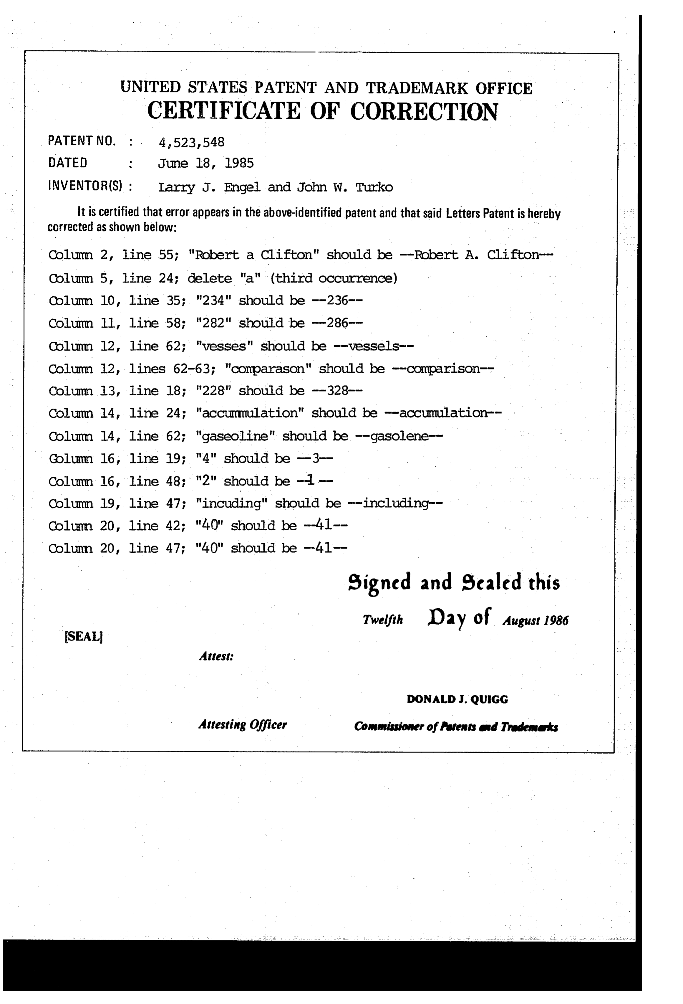
UNITED STATES PATENT AND TRADEMARK OFFICE
CERTIFICATE OF CORRECTION
INVENTOR(S) : Larry J. Engel and John W. Turko it is certified that error appears in the above-identified patent and that said Letters Patent is hereby corrected as shown below:
Column 2, line 55; "Robert a Clifton" should be --Robert A. Clifton Column 5, line 24; delete "a" (third OCCurrence)
Column ll, line 58; "282" should be -286
Column 12, line 62; "vesses" should be --vessels-- Colum 12, lines 62-63; "comparason" should be -comparison
Column l4, line 24; "accumulation" should be -accumulation -- Column 14 line 62; "gaseoline" should be -gasolene
Column 16, line 48; 12 it should be - -
Column l9, line 47; "including" should be -including
signed and Sealed this
Twelfth Day of August 1986
SEAL
Attest
DONALDJ. QUIGG
Attesting Officer Commissioner offents and Trademarks
Provenance
- Collection
- Cited prior art
- Original PDF
- patentimages.storage.googleapis.com →
- Filed
- 1983-04-13
- Pages
- 19
- Method
- pdftotext (the PDF's own text layer) + pdftoppm 300dpi page scans
- Source
- Google Patents bibliographic record
- Granted
- 1985-06-18
- Inventors
- Larry J. Engel; John W. Turko; Michigan Consolidated Gas Co
- Transcribed from
- patentimages.storage.googleapis.com →