patent · US4783966
Multi-staged internal combustion engine
15 November 1988
Page 1 — bibliographic record
United States Patent (19) 11 Patent Number: 4,783,966 Aldrich 45) Date of Patent: Nov. 15, 1988 54 MULTI-STAGED INTERNAL COMBUSTION 4,115,037 9/1978 Butler .................................. 417/341 ENGINE 4,169,451 10/1979 Niggemeyer ........................ 123/202 4,174,683 11/1979 Vivian ........ ... 123/48 C (76 Inventor: Clare A. Aldrich, 296 E. 4,493,296 l/1985 Williams ..... ... 123/55 AA Gainsborough Rd., Thousand Oaks, 4,539,946 9/1985 Hedelin ............................. 123/48 A
Primary Examiner-Stephen F. Husar 21 Appl. No.: 91.978 Attorney, Agent, or Firm-Kelly, Bauersfeld & Lowry (22) Filed: Sep. 1, 1987 (57) ABSTRACT (51 Int. Cl." ................................................ F02G 3/00 The positive displacement internal combustion engine 52 U.S. C. ........................................ 60/622; 60/599; has multiple stages of compression and expansion. After 60/621 an initial compression, the working fluid is contained at 58) Field of Search ................. 60/620, 621, 622, 623, elevated pressure and temperature. Valve controls on 60/599; 123/563 the initial compression can limit the thru-put of working 56) References Cited fluid. Limiting the thru-put controls the pressure and
A heat exchanger cools the working fluid before it 423,224 3/1890 Drautz . enters a conventional spark ignition "combustion' cyl 1,159,633 11/1915 Wilkinson . inder. After the combustion of fuel in air in a conven 1,904,070 4/1933 Morgan ................................. 60/620 tional Otto or Diesel cycle the exhaust gas does further 2,873,574 2/1959 Webb . expansion in a post expansion stage. The efficiency
3,267,661 8/1966 Petrie................................ 60/620 X benefits of the engine's high expansion ratio are realiz 3,782,337 1/1974 Feller . able because of reductions in friction, fluid flow and 3,783,615 1/1974 Hubers . heat transfer losses.
3,914,944 10/1975 Schmidt et al. ................ 123/563 X 42 Claims, 5 Drawing Sheets
Page 2
HGSNag is fire. H H 25cc 3 CoCoo
N TNCsaoszekaavs/CM 2CdCoo
careese- is ex-aest fas Cod
COO
NaN
Seoo eos
celess: NTT IMTH
III
| | TANNE,
TNT
NTA
| rearrestro-NN . N r
2.0 /.5 /.co. 1 .7, as . As .C. . 3 .2 . 15 . . . oas.o7.cog.oC.
Page 3
Drawing sheet — no readable text.
Page 4
Drawing sheet — no readable text.
Page 5
Drawing sheet — no readable text.
Page 6
Drawing sheet — no readable text.
Page 7
available work with heat loss. Heat loss not only results
MULT-STAGED INTERNAL COMBUSTION in theoretical loss of available energy, but the engine ENGINE must also drive equipment to cool heated engine parts.
BACKGROUND OF THE INVENTION
Throttling the charge (the amount) of fuel/air mix ture flowing to the combustion chamber at any time is
The present invention relates to a positive displace the conventional way of varying engine torque and ment internal combustion engine with multiple stages of power. Throttling results in large efficiency losses, compression and expansion reaching very high pres which are caused by fluid flow losses and pumping. To sures and having density control of engine torque. compensate for these losses, vehicles use transmissions It is known that increasing the expansion ratio of a 10 of up to five speeds for automobiles and up to twenty reciprocating internal combustion engine extracts more speeds for large trucks.
energy during the expansion of the combustion gases. Another problem with conventional engines occurs Therefore, the thermodynamic efficiency increases as because of incomplete mixture of fuel and air injected the expansion ratio increases. For constant volume into the combustion chamber. If the fuel and air were combustion, the theoretical thermal efficiency equals: 15 mixed uniformly a leaner mixture could be used. 1-1/r(k-1) (1) SUMMARY OF THE INVENTION One of the principal objects of the present invention where r is the expansion ratio and k is the adiabatic is to disclose and provide an internal combustion engine expansion coefficient, which for air at room tempera 20 that is substantially more efficient than present engines. ture is 1.4.
Conventional Otto cycle engines usually have the The theoretical efficiency in standard engines is roughly estimated by the equation:
same compression and expansion ratios, which are se lected so that the fuel/air mixture is compressed to a 1-1/r(0.3) (2) point below which spark ignition does not cause detona 25 .
tion. Detonation depends on the anti-knock characteris Raising the expansion ratio, r, increases efficiency. The tics of the fuel and on the combustion chamber design. compression ratio is also increased. The present inven The ratio is usually about 7 in automobile engines using tion uses compresion ratios as high as 40 to 1 or higher. regular fuel, but the ratio can be over 10 in aircraft When the fuel/air mixture is compressed that much, the engines. Diesel engines also have equal compression 30 increase in temperature would normally cause detona and expansion ratios, but the air is compressed to a point tion during burning. The present invention avoids the where the injection of fuel causes ignition. detonation that would take place at the higher compres Multiple staging has been known as a way of using sion ratios because compression which takes place in more of the available energy left after expansion in an two or more stages with cooling before the last stage of earlier stage. Early multi-staging is taught in conjunc 35 compression lowers the final compression temperature tion with steam engines. Drautz, U.S. Pat. No. 423,224 below that of a conventional engine. (1890) is an example of a multi-stage steam engine. The The higher density of the working fluid reduces the last stage may expand steam to sub-atmospheric pres combustion chamber dimensions, which in turn reduces sure. Turbo machinery has also used multi-staging. In the time of ignition and burning. The tendency to deto reciprocating aircraft engines, the supercharger is nate is also reduced as the time of ignition and burning driven by elevated pressure exhaust gas at high temper is reduced.
ature to drive a compressor to compensate for de The next principal object of the present invention is creased air density at high altitude Multi-staging has to provide a more efficient means of varying the output also been proposed for positive displacement rotary torque over a wide range of values. Present standard engines such as that disclosed in Hubers, U.S. Pat. No. 45 engines vary torque with multiple gear transmissions. 3,783,615 (1974). Multiple staging was important in Achieving this objective in cars or trucks could reduce rotary engines so that the engines could reach conven transmission size and decrease the number of gear tional compression ratios because positive displacement changes. Controlling the fuel/air ratio and throttle con mechanisms in rotary engines have low efficiencies trols provide variation in current engines, but efficiency except at low pressure ratios. 50 drops off rapidly at low torque. Thermodynamic advantages of multi-staging are un The multi-staged engine of the present invention derstood, but the problems in achieving these advan provides an additional means, which is more efficient, tages in a practical manner have prevented their imple for controlling the density of the working fluid. The mentation. Theoretical problems such as detonation, controlled in the present invention limits the admission increased heat transfer losses, large mechanical forces, 55 of working fluid to the compressor or limits the flow increased friction losses, transfer losses, large size, con from the compressor to the accumulator. These meth plexity and many other smaller problems have contrib ods drop the compression ratio so there is some loss in uted to the lack of interest in developing such an engine. efficiency for thermodynamic reasons, but there is not Moreover, many of the tradeoffs in basic engine design an increase in pumping losses that occur with standard took place when the fuel was very inexpensive and 60 throttling. Losses from fluid flow, friction and heat there was less demand for increased engine efficiency. transfer do not drop as fast as the drop in density. Pollution, heat dissipation and low efficiency for The next primary object of the present invention is to power variation are among the potential problems con disclose and provide an internal combustion engine of fronting present engineers. Engine efficiency also suf reduced size and weight. Each piston in a standard, four fers from heat dissipation, which can increase as com 65 cylinder, four cycle engine has a power stroke every pression and expansion ratios increase. The heat loss 720. In the multi-staged engine of the present inven represents energy not available for useful work. Con tion, a post-expansion piston has a power stroke every ventional engines have no means to minimize the loss of 360, twice as often as the four cycle combustion stroke.
Page 8
Thus, the post-expansion stage can take the place of two tional four cylinder engine. By proper coordination of combustion cylinders. Therefore, the multi-staged en the valves between the combustion and post-expansion gine of the present invention with two combustion cyl chambers, there can be an increase in efficiency for inders and a single post-expansion cylinder can provide reasons explained in more detail below. The design of approximately the same power uniformity as a four the piston face, which can occupy portions of the pas cylinder standard engine. sages between the chambers, can affect the flow of Locating the post-expansion chamber between and in gases, but is designed to reduce the post-expansion dead line with two combustion chambers and having the two volumes.
combustion pistons 180 out of phase with the larger The present invention takes advantage of pre-com and heavier post-expansion piston, makes a balanceable 10 pression so that the actual compression that takes place engine arrangement. in the combustion chambers can be minimized. The A further object of the present invention is to provide device can use smaller pistons. Moreover, the present an engine that can use two sides of single piston for the invention can use as few as two combustion chambers. different tasks, one side for pre-compression of the The reduced size and number of the combustion cham working fluid before combustion and the other side for 15 bers reduces the heat transfer area and ultimate heat post-expansion of the working fluid. The use of such a transfer to the surroundings.
dual piston eliminates one set of large piston rings and Heat loss represents energy that is not available for reduces the overall size of the engine. work. It is recognized that because of additional heat If the pre-compression cylinder is to have the same losses, raising the compression ratio above customary working fluid volume intake as standard engine cylin amounts in conventional engines can result in decreased ders, the pre-compression piston must have twice the output. A decrease in heat transfer results in a more area of the piston of a standard four cylinder engine. efficient engine. The lower compression ratios that take The greater efficiency of the present invention reduces place in the combustion chamber and a lower fuel to air the required fuel/air mixture intake, but a lower fuel/air ratio gives lower combustion temperatures. This de ratio (for less pollution) increases the required air in 25 crease permits higher combustion chamber surface tem take. With other factors, the area of the pre-compres peratures.
sion and post-expansion pistons could be about 2 times The present invention can use one direction of the the area of standard, comparable engine pistons. The stroke of the piston to compress the working fluid and small combustion cylinders in the present invention are to receive and expand combustion products on the about one-third the diameter of the post-expansion and 30 other side of the piston. By using the same piston to pre-compression pistons. perform two different functions, engine size can be The next principal object of the present invention is greatly reduced. The various other components that to provide an internal combustion engine with reduced function with the piston such as crankshaft eccentrics, pollution. It is known that higher engine temperatures bearings, piston rods and rings can be reduced also. increase the concentration of pollutants in the working 35 The pre-compression piston could first compress and fluid. The engine of the present invention can operate at then discharge the fuel/air mixture through a valve lower fuel/air ratios, which in turn reduces the temper normally during the approximately the last 50 of crank ature and pollution. The lower compression ratio in the rotation. The engine combustion chamber takes in the combustion chambers of the present invention reduces working fluid during approximately 180 of crank rota the temperature further. That occurs because the fuel 40 tion. Pressure variations in the combustion chamber /air mixture is ignited from a lower starting tempera which would be caused by this lack of matching, can be ture. Flame travel velocity decreases at lower fuel/air reduced by discharging the working fluid from the ratios. The present invention uses small combustion pre-compressor in a gas reservoir of substantial volume, chambers to compensate for decreased velocity of flame the accumulator in the present invention. A larger res travel through decreased distance of flame travel. 45 ervoir decreases the pressure fluctuations. The volume The present invention also uses an accumulator after of the reservoir also includes the volume of all ducts pre-compression but before cooling. The accumulator between the pre-compressor discharge valve and the provides complete vaporization of the fuel, which im combustion chamber intake valves and the high pres proves its combustion characteristics. Also, a more sure passages, collectors and headers of the heat ex efficient engine uses less fuel, which proportionally 50 changer that is between the valves. Dynamic acumula results in less pollution. tors and compressors that have a gas delivery but more The next principal object of the present invention is closely match the intake requirements of the combus to disclose and provide a spark ignition engine that can tion chambers (e.g. Lysholm compressors, multiple use a wider range of fuels. Because the engine cools the piston compressors) will greatly reduce the required fuel/air mixture before the final stage of compression 55 reservoir volume.
and because of its lower combustion stage compression Another factor affecting accumulator size will be the ratio, it operates at reduced temperatures. The engine design of the engine accessories. A tank accumulator does not require higher octane fuel that previous high could be reduced in size substantially, and could even compression engines require. Spark ignition airplane be eliminated if the ducts and heat exchanger collectors engines would not require special fuels. 60 and heaters are oversized. If the reservoir volume is A further expansion of the working medium takes very large, the response to the accelerator push rod is place in a post-expansion cylinder. The expanding slow because time is required to build up or drop off working medium acts on a post-expansion piston in the pressure. This slow response makes starting take less post-expansion cylinder, which drives the crankshaft energy for cranking. If faster response is desired a dy 180 of crankshaft phase later than the pistons of the 65 namic accumulator or a smaller reservoir volume can be combustion chambers. This arrangement allows the used. This would require larger starters and batteries. multi-staged engine with two combustion chambers to Although the present invention uses a tank as an accu have power output of similar uniformity to a conven mulator, the accumulator of the present invention need
Page 9
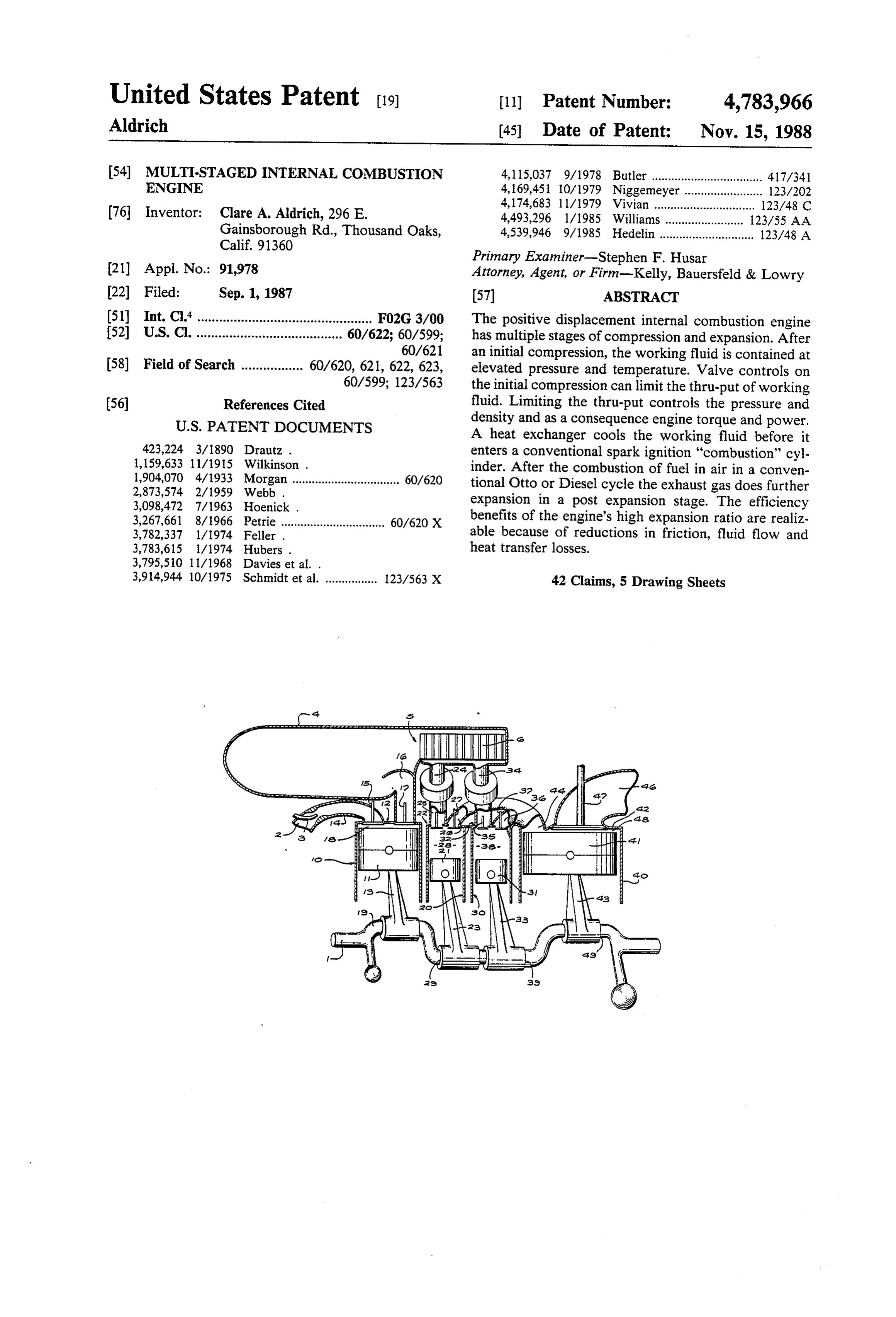
not be an added object. Any means for providing high FIG. 4 is a cut-away view of another specific embodi pressure gas holding capacity sufficient to reduce pres ment of the multi-staged internal combustion engine of sure variations from the pre-compressor as a result of the present invention.
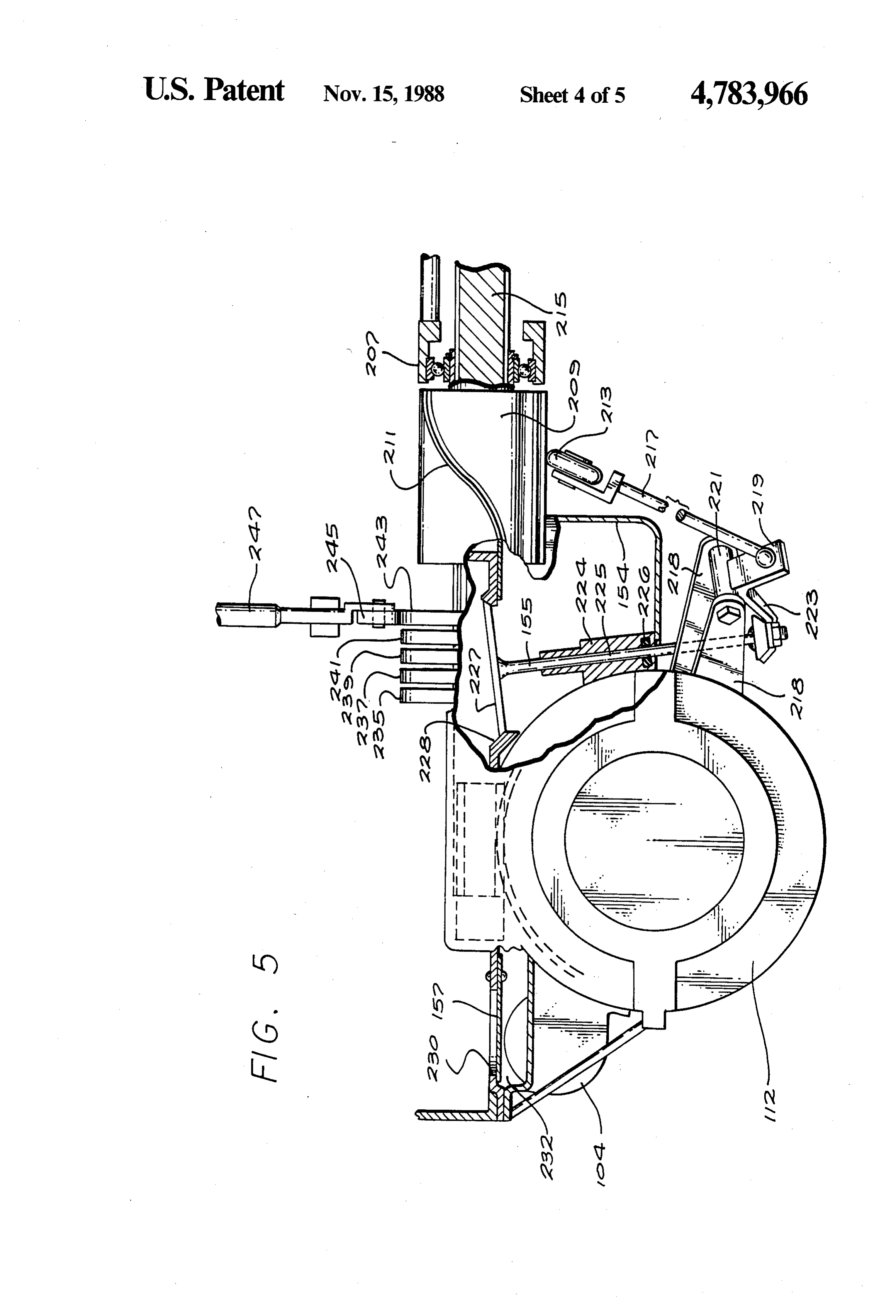
combustion chamber intake to decrease fluid flow losses FIG. 5 is a partial end view of FIG. 4 showing some would perform the function of an accumulator. of the components of the multi-staged engine of the The present invention includes a crankshaft or other present invention. Some of the cams that drive the valve comparable piston driver. The crankshaft drives an are shown in detail.
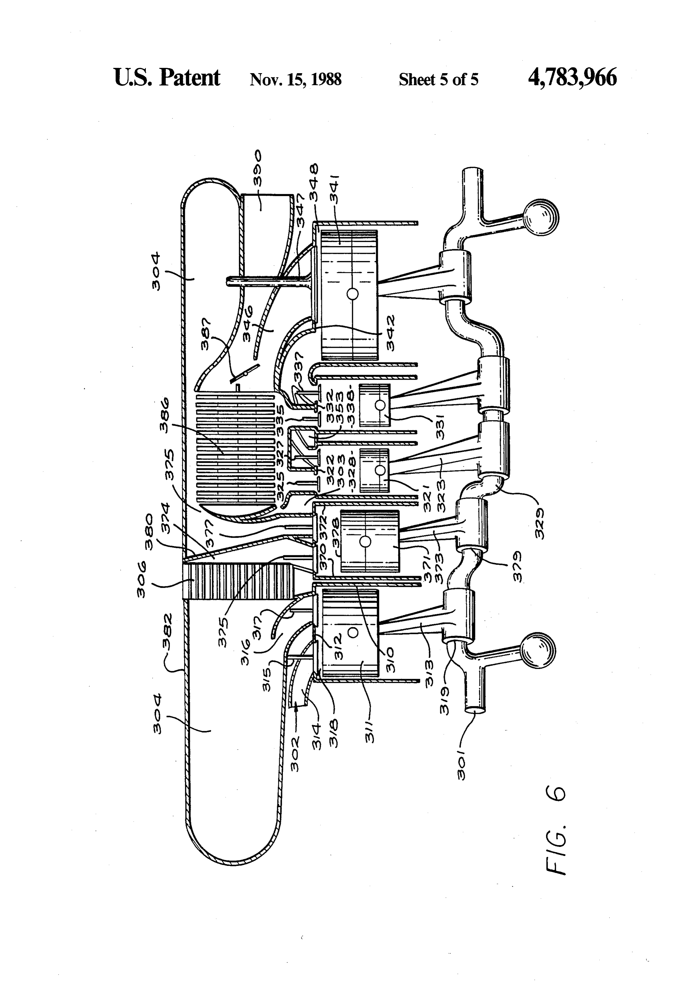
intake or pre-compression piston in an intake or pre FIG. 6 is another idealized representation of the en compression cylinder. During the piston movement of gine of the present invention. It has two pre-compres the piston away from its cylinder head, the fuel/air O sion stages rather than the single stage that the FIG. 3 mixture is drawn into the pre-compression cylinder. engine has.
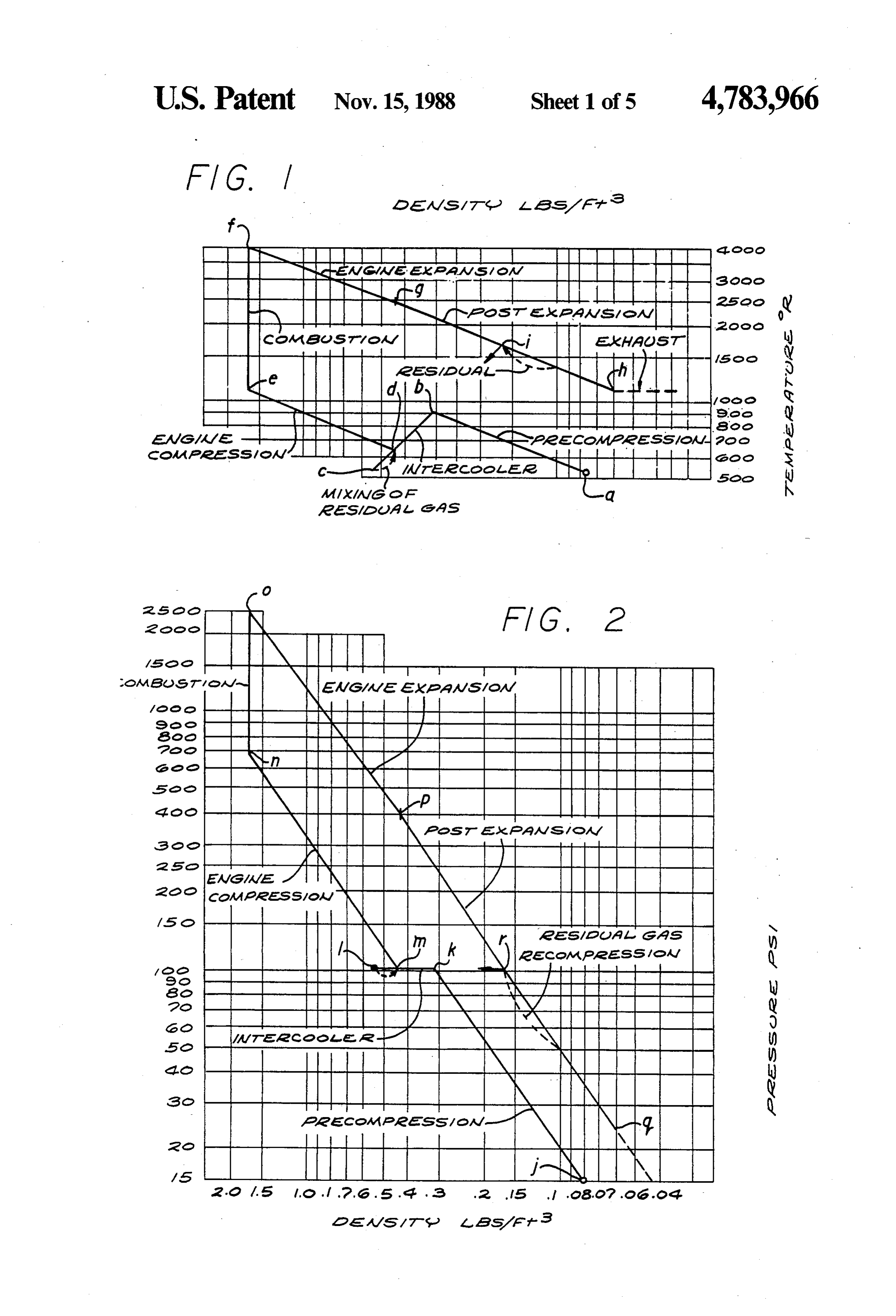
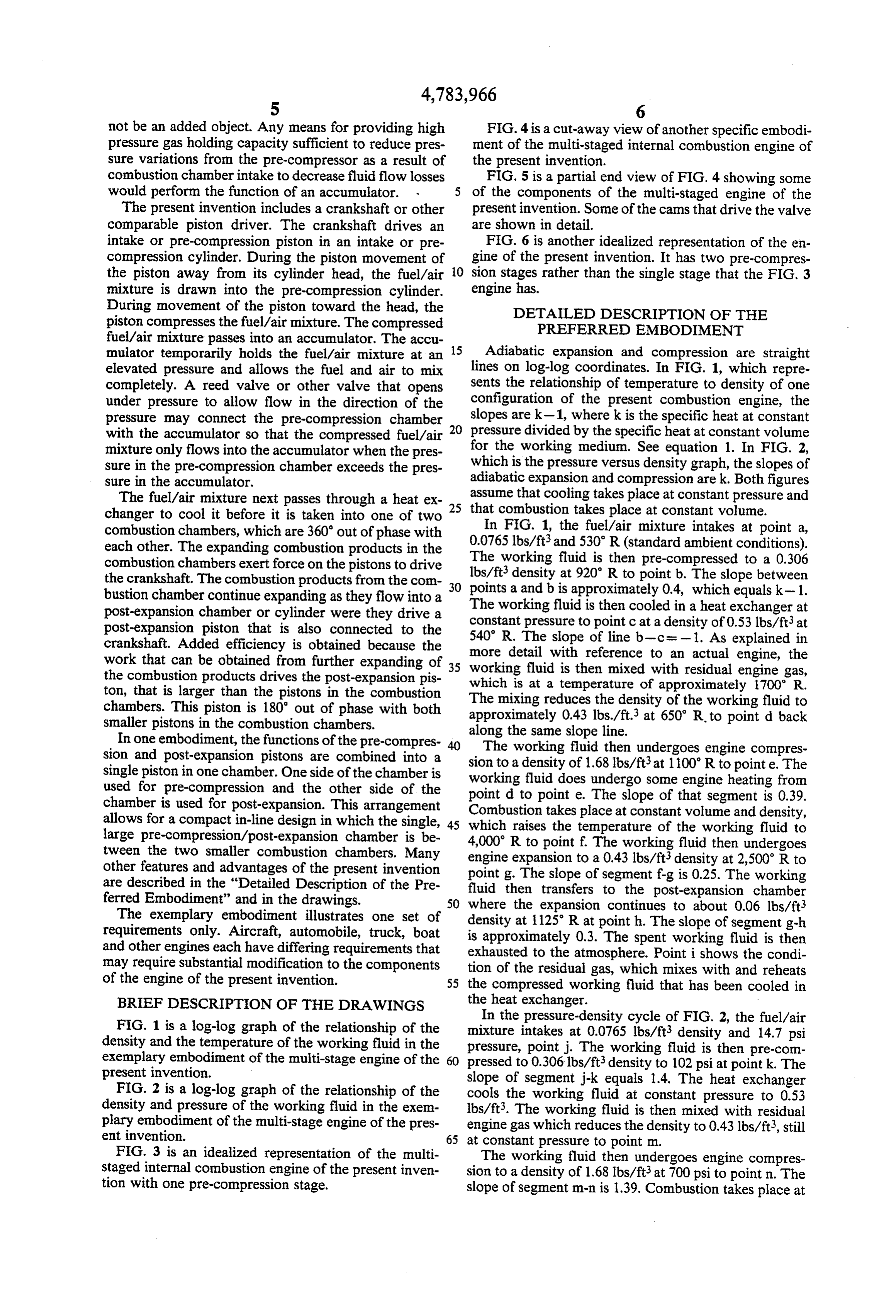
During movement of the piston toward the head, the DETALED DESCRIPTION OF THE piston compresses the fuel/air mixture. The compressed PREFERRED EMBODIMENT fuel/air mixture passes into an accumulator. The accu 15 mulator temporarily holds the fuel/air mixture at an Adiabatic expansion and compression are straight elevated pressure and allows the fuel and air to mix lines on log-log coordinates. In FIG. 1, which repre completely. A reed valve or other valve that opens sents the relationship of temperature to density of one under pressure to allow flow in the direction of the configuration of the present combustion engine, the pressure may connect the pre-compression chamber slopes are k-1, where k is the specific heat at constant with the accumulator so that the compressed fuel/air 20 pressure divided by the specific heat at constant volume mixture only flows into the accumulator when the pres for the working medium. See equation 1. In FIG. 2, sure in the pre-compression chamber exceeds the pres which is the pressure versus density graph, the slopes of sure in the accumulator. adiabatic expansion and compression are k. Both figures The fuel/air mixture next passes through a heat ex 25 assume that cooling takes place at constant pressure and changer to cool it before it is taken into one of two that combustion takes place at constant volume. combustion chambers, which are 360 out of phase with In FIG. 1, the fuel/air mixture intakes at point a,
each other. The expanding combustion products in the The working lbs/ft3and 530 R (standard ambient conditions). combustion chambers exert force on the pistons to drive lbs/ft3 fluid is then pre-compressed to a 0.306 the crankshaft. The combustion products from the con points a and b isatapproximately density 920 R to point b. The slope between 0.4, which equals k- 1.
bustion chamber continue expanding as they flow into a 30 The working fluid is then cooled in a heat exchanger at post-expansion chamber or cylinder were they drive a constant pressure to point c at a density of 0.53 lbs/ft at post-expansion piston that is also connected to the 540 R. The slope of line b-c=-1. As crankshaft. Added efficiency is obtained because the more detail with reference to an actual explained in work that can be obtained from further expanding of 35 working fluid is then mixed with residual engine, the the combustion products drives the post-expansion pis which is at a temperature of approximatelyengine gas,
ton, that is larger than the pistons in the combustion The mixing reduces the density of the working fluid to chambers. This piston is 180° out of phase with both approximately 0.43 lbs./ft3 at 650 R to point d back smaller pistons in the combustion chambers. along the same slope line.
In one embodiment, the functions of the pre-compres The working fluid then undergoes engine compres sion and post-expansion pistons are combined into a sion to a density of single piston in one chamber. One side of the chamber is working fluid does1.68lbs/ft3at undergo some 1100 R to pointe. The engine heating from used for pre-compression and the other side of the point d to point e. The slope of that segment is 0.39. chamber is used for post-expansion. This arrangement Combustion takes place at constant volume and density, allows for a compact in-line design in which the single, 45 which raises the temperature of the working fluid to large pre-compression/post-expansion chamber is be 4,000 R to point f. The working fluid then undergoes tween the two smaller combustion chambers. Many engine expansion to a 0.43 lbs/ft3 density at 2,500 R to other features and advantages of the present invention point g. The slope of segment f-g is 0.25. The working are described in the "Detailed Description of the Pre fluid then transfers to the post-expansion chamber ferred Embodiment” and in the drawings. 50 where the expansion continues to about 0.06 lbs/ft The exemplary embodiment illustrates one set of density at 1125R at pointh. The slope of segment g-h requirements only. Aircraft, automobile, truck, boat is approximately 0.3. The spent working fluid is then and other engines each have differing requirements that exhausted to the atmosphere. Point i shows the condi may require substantial modification to the components tion of the residual gas, which mixes with and reheats of the engine of the present invention. 55 the compressed working fluid that has been cooled in BRIEF DESCRIPTION OF THE DRAWINGS the heat exchanger.
In the pressure-density cycle of FIG. 2, the fuel/air
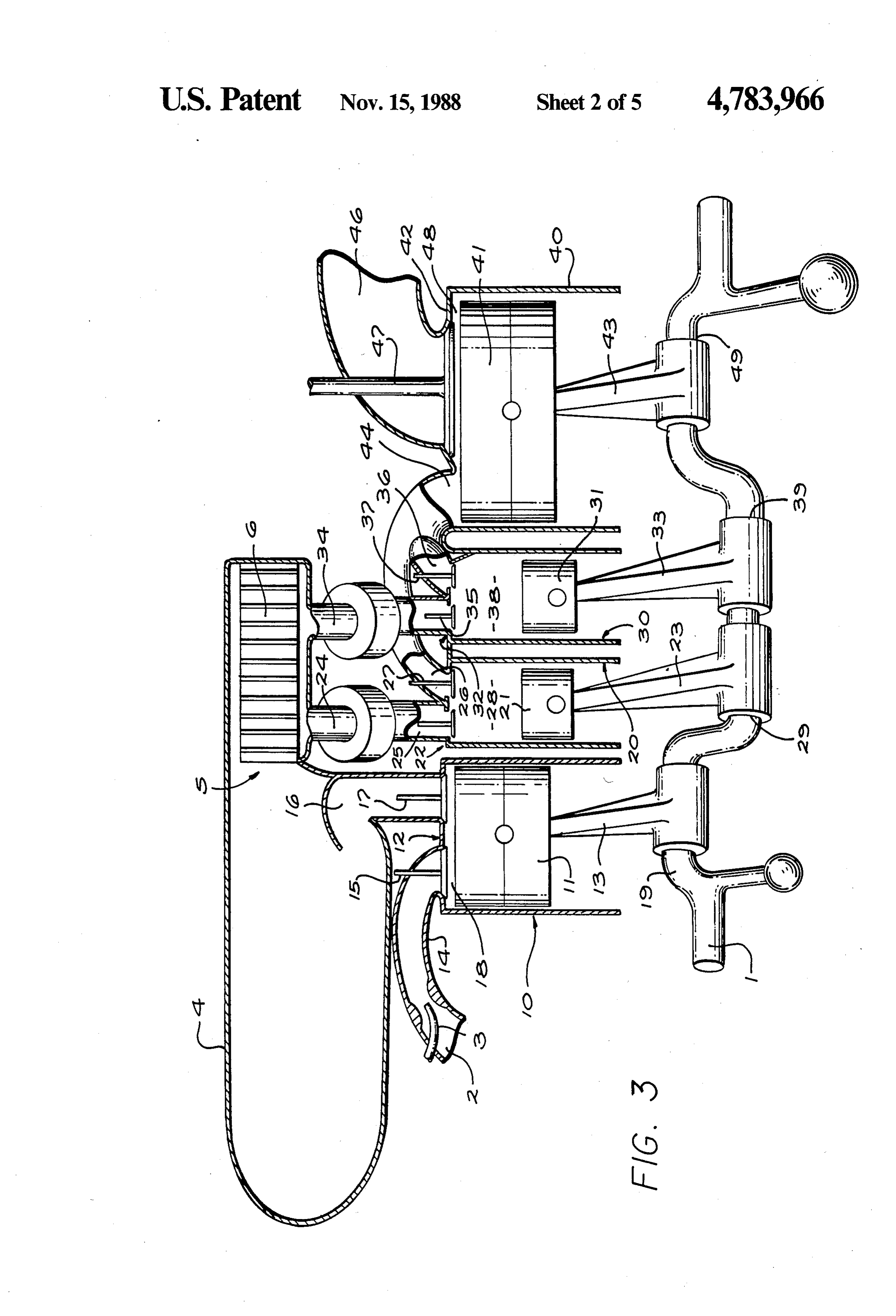
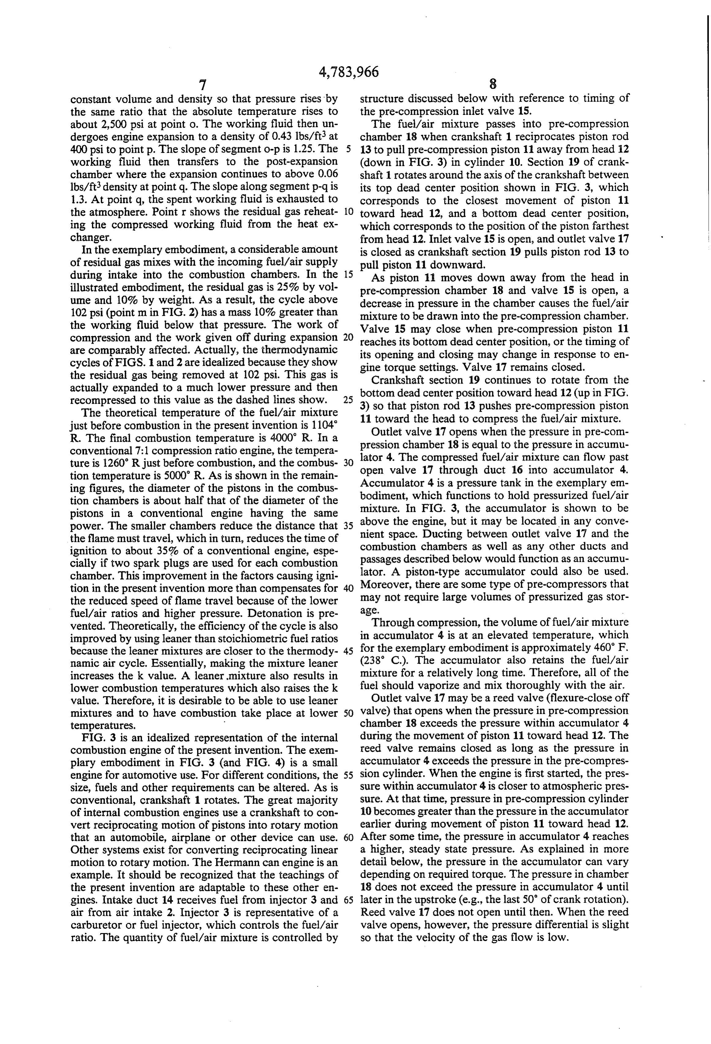
FIG. 1 is a log-log graph of the relationship of the mixture intakes at 0.0765 lbs/ft density and 14.7 psi density and the temperature of the working fluid in the pressure, point j. The working fluid is then pre-com exemplary embodiment of the multi-stage engine of the 60 pressed to 0.306 lbs/ft3 density to 102 psi at point k. The present invention. slope of segment j-k equals 1.4. The heat exchanger FIG. 2 is a log-log graph of the relationship of the cools the working fluid at constant pressure to 0.53 density and pressure of the working fluid in the exem lbs/ft3. The working fluid is then mixed with residual plary embodiment of the multi-stage engine of the pres engine gas which reduces the density to 0.43 lbs/ft, still ent invention. 65 at constant pressure to point m. FIG. 3 is an idealized representation of the multi The working fluid then undergoes engine compres staged internal combustion engine of the present inven sion to a density of 1.68 lbs/ft3 at 700 psi to point n. The tion with one pre-compression stage. slope of segment m-n is 1.39. Combustion takes place at
Page 10
constant volume and density so that pressure rises by structure discussed below with reference to timing of the same ratio that the absolute temperature rises to the pre-compression inlet valve 15. about 2,500 psi at point o. The working fluid then un The fuel/air mixture passes into pre-compression dergoes engine expansion to a density of 0.43 lbs/ft at chamber 18 when crankshaft 1 reciprocates piston rod 400 psi to point p. The slope of segment o-p is 1.25. The 13 to pull pre-compression piston 11 away from head 12 working fluid then transfers to the post-expansion (down in FIG. 3) in cylinder 10. Section 19 of crank chamber where the expansion continues to above 0.06 shaft 1 rotates around the axis of the crankshaft between lbs/ft density at point q. The slope along segment p-q is its top dead center position shown in FIG. 3, which 1.3. At point q, the spent working fluid is exhausted to corresponds to the closest movement of piston 11 the atmosphere. Point r shows the residual gas reheat O toward head 12, and a bottom dead center position, ing the compressed working fluid from the heat ex which corresponds to the position of the piston farthest changer. from head 12. Inlet valve 15 is open, and outlet valve 17 In the exemplary embodiment, a considerable amount is closed as crankshaft section 19 pulls piston rod 13 to of residual gas mixes with the incoming fuel/air supply pull piston 11 downward.
during intake into the combustion chambers. In the 15 As piston 11 moves down away from the head in illustrated embodiment, the residual gas is 25% by vol pre-compression chamber 18 and valve 15 is open, a ume and 10% by weight. As a result, the cycle above decrease in pressure in the chamber causes the fuel/air 102 psi (point m in FIG. 2) has a mass 10% greater than mixture to be drawn into the pre-compression chamber. the working fluid below that pressure. The work of Valve 15 may close when pre-compression piston 11 compression and the work given off during expansion reaches its bottom dead center position, or the timing of are comparably affected. Actually, the thermodynamic its opening and closing may change in response to en cycles of FIGS. 1 and 2 are idealized because they show gine torque settings. Valve 17 remains closed. the residual gas being removed at 102 psi. This gas is Crankshaft section 19 continues to rotate from the actually expanded to a much lower pressure and then bottom dead center position toward head 12 (up in FIG. recompressed to this value as the dashed lines show. 25 3) so that
The theoretical temperature of the fuel/air mixture 11 toward piston the rod 13 pushes pre-compression piston head to compress the fuel/air mixture.
just before combustion in the present invention is 1104 Outlet valve 17 opens when the pressure in pre-com R. The final combustion temperature is 4000 R. In a pression chamber 18 is equal to the pressure in accumu conventional 7:1 compression ratio engine, the tempera lator 4. The compressed fuel/air mixture can flow past ture is 1260 Rjust before combustion, and the combus 30 open valve 17 through duct 16 into accumulator 4. tion temperature is 5000 R. As is shown in the remain ing figures, the diameter of the pistons in the combus Accumulator 4 is a pressure tank in the exemplary em bodiment, which functions to hold pressurized fuel/air tion chambers is about half that of the diameter of the pistons in a conventional engine having the same mixture. In FIG. 3, the accumulator is shown to be power. The smaller chambers reduce the distance that 35 above the engine, but it may be located in any conve the flame must travel, which in turn, reduces the time of nient space. Ducting between outlet valve 17 and the ignition to about 35% of a conventional engine, espe combustion chambers as well as any other ducts and cially if two spark plugs are used for each combustion passages described below would function as an accumu chamber. This improvement in the factors causing igni lator. A piston-type accumulator could also be used. tion in the present invention more than compensates for Moreover, there are some type of pre-compressors that the reduced speed of flame travel because of the lower age.may not require large volumes of pressurized gas stor fuel/air ratios and higher pressure. Detonation is pre vented. Theoretically, the efficiency of the cycle is also Through compression, the volume of fuel/air mixtur improved by usingleaner than stoichiometric fuel ratios in accumulator 4 is at an elevated temperature, which because the leaner mixtures are closer to the thermody 45 for the exemplary embodiment is approximately 460 F. namic air cycle. Essentially, making the mixture leaner (238 C.). The accumulator also retains the fuel/air increases the k value. A leaner mixture also results in mixture for a relatively long time. Therefore, all of the lower combustion temperatures which also raises the k fuel should vaporize and mix thoroughly with the air. value. Therefore, it is desirable to be able to use leaner Outlet valve 17 may be a reed valve (flexure-close off mixtures and to have combustion take place at lower 50 valve) that opens when the pressure in pre-compression temperatures. chamber 18 exceeds the pressure within accumulator 4 FIG. 3 is an idealized representation of the internal during the movement of piston 11 toward head 12. The combustion engine of the present invention. The exem reed valve remains closed as long as the pressure in plary embodiment in FIG. 3 (and FIG. 4) is a small accumulator 4 exceeds the pressure in the pre-compres engine for automotive use. For different conditions, the 55 sion cylinder. When the engine is first started, the pres size, fuels and other requirements can be altered. As is sure within accumulator 4 is closer to atmospheric pres conventional, crankshaft 1 rotates. The great majority sure. At that time, pressure in pre-compression cylinder of internal combustion engines use a crankshaft to con 10 becomes greater than the pressure in the accumulator vert reciprocating motion of pistons into rotary motion earlier during movement of piston 11 toward head 12. that an automobile, airplane or other device can use. 60 After some time, the pressure in accumulator 4 reaches Other systems exist for converting reciprocating linear a higher, steady state pressure. As explained in more motion to rotary motion. The Hermann can engine is an detail below, the pressure in the accumulator can vary example. It should be recognized that the teachings of depending on required torque. The pressure in chamber the present invention are adaptable to these other en 18 does not exceed the pressure in accumulator 4 until gines. Intake duct 14 receives fuel from injector 3 and 65 later in the upstroke (e.g., the last 50 of crank rotation). air from air intake 2. Injector 3 is representative of a Reed valve 17 does not open until then. When the reed carburetor or fuel injector, which controls the fuel/air valve opens, however, the pressure differential is slight ratio. The quantity of fuel/air mixture is controlled by so that the velocity of the gas flow is low.
Page 11
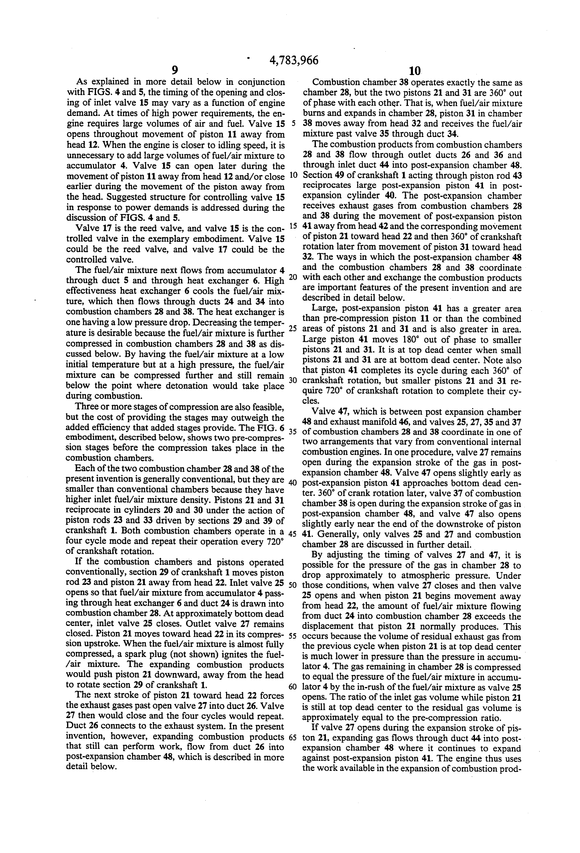
As explained in more detail below in conjunction Combustion chamber 38 operates exactly the same as with FIGS. 4 and 5, the timing of the opening and clos chamber 28, but the two pistons 21 and 31 are 360 out ing of inlet valve 15 may vary as a function of engine of phase with each other. That is, when fuel/air mixture demand. At times of high power requirements, the en burns and expands in chamber 28, piston 31 in chamber gine requires large volumes of air and fuel. Valve 15 38 moves away from head 32 and receives the fuel/air opens throughout movement of piston 11 away from mixture past valve 35 through duct 34.
head 12. When the engine is closer to idling speed, it is The combustion products from combustion chambers unnecessary to add large volumes of fuel/air mixture to 28 and 38 flow through outlet ducts 26 and 36 and accumulator 4. Valve 15 can open later during the through inlet duct 44 into post-expansion chamber 48. movement of piston 11 away from head 12 and/or close 10 Section 49 of crankshaft 1 acting through piston rod 43 earlier during the movement of the piston away from reciprocates large post-expansion piston 41 in post the head. Suggested structure for controlling valve 15 expansion cylinder 40. The post-expansion chamber in response to power demands is addressed during the receives exhaust gases from combustion chambers 28 discussion of FIGS. 4 and 5. and 38 during the movement of post-expansion piston Valve 17 is the reed valve, and valve 15 is the con 15 41 away from head 42 and the corresponding movement trolled valve in the exemplary embodiment. Valve 15 of piston 21 toward head 22 and then 360 of crankshaft could be the reed valve, and valve 17 could be the rotation later from movement of piston 31 toward head controlled valve. 32. The ways in which the post-expansion chamber 48 The fuel/air mixture next flows from accumulator 4 and the combustion chambers 28 and 38 coordinate through duct 5 and through heat exchanger 6. High with each other and exchange the combustion products
are important features of the present invention and are effectiveness heat exchanger 6 cools the fuel/air mix described ture, which then flows through ducts 24 and 34 into in detail below. combustion chambers 28 and 38. The heat exchanger is than Large, post-expansion piston 41 has a greater area one having a low pressure drop. Decreasing the temper pre-compression piston 11 or than the combined ature is desirable because the fuel/air mixture is further 25 areas of pistons 21 and 31 and is also greater in area. compressed in combustion chambers 28 and 38 as dis pistons Large piston 41 moves 180 out of phase to smaller cussed below. By having the fuel/air mixture at a low pistons 21 21 and 31. It is at top dead center when small initial temperature but at a high pressure, the fuel/air that and 31 are at bottom dead center. Note also piston mixture can be compressed further and still remain 30 crankshaft rotation, 41 completes its cycle during each 360 of below the point where detonation would take place quire 720" of crankshaft but smaller pistons 21 and 31 re during combustion. rotation to complete their cy cles.
Three or more stages of compression are also feasible, but the cost of providing the stages may outweigh the 48Valve and 47, which is between post expansion chamber exhaust manifold 46, and valves 25, 27, 35 and 37 added efficiency that added stages provide. The FIG. 6 35 of combustion chambers 28 and 38 coordinate in one of embodiment, described below, shows two pre-compres two arrangements that vary from conventional internal sion stages before the compression takes place in the combustion engines. In one procedure, valve 27 remains combustion chambers. open during the expansion stroke of the gas in post Each of the two combustion chamber 28 and 38 of the expansion chamber 48. Valve 47 opens slightly early as present invention is generally conventional, but they are post-expansion piston 41 approaches bottom dead cen smaller than conventional chambers because they have ter. 360' of crank rotation later, valve 37 of combustion higher inlet fuel/air mixture density. Pistons 21 and 31 chamber 38 is open during the expansion stroke of gas in reciprocate in cylinders 20 and 30 under the action of post-expansion chamber 48, and valve 47 also opens piston rods 23 and 33 driven by sections 29 and 39 of slightly early near the end of the downstroke of piston crankshaft 1. Both combustion chambers operate in a 45 41. Generally, only valves 25 and 27 and combustion four cycle mode and repeat their operation every 720 chamber 28 are discussed in further detail. of crankshaft rotation. By adjusting the timing of valves 27 and 47, it is If the combustion chambers and pistons operated possible for the pressure of the gas in chamber 28 to conventionally, section 29 of crankshaft 1 moves piston drop approximately to atmospheric pressure. Under rod 23 and piston 21 away from head 22. Inlet valve 25 50 those conditions, when valve 27 closes and then valve opens so that fuel/air mixture from accumulator 4 pass 25 opens and when piston 21 begins movement away ing through heat exchanger 6 and duct 24 is drawn into from head 22, the amount of fuel/air mixture flowing combustion chamber 28. At approximately bottom dead from duct 24 into combustion chamber 28 exceeds the center, inlet valve 25 closes. Outlet valve 27 remains displacement that piston 21 normally produces. This closed. Piston 21 moyes toward head 22 in its compres 55 occurs because the volume of residual exhaust gas from sion upstroke. When the fuel/air mixture is almost fully the previous cycle when piston 21 is at top dead center compressed, a spark plug (not shown) ignites the fuel is much lower in pressure than the pressure in accumu /air mixture. The expanding combustion products lator 4. The gas remaining in chamber 28 is compressed would push piston 21 downward, away from the head to equal the pressure of the fuel/air mixture in accumu to rotate section 29 of crankshaft 1. lator 4 by the in-rush of the fuel/air mixture as valve 25 The next stroke of piston 21 toward head 22 forces opens. The ratio of the inlet gas volume while piston 21 the exhaust gases past open valve 27 into duct 26. Valve is still at top dead center to the residual gas volume is 27 then would close and the four cycles would repeat. approximately equal to the pre-compression ratio. Duct 26 connects to the exhaust system. In the present If valve 27 opens during the expansion stroke of pis invention, however, expanding combustion products 65 ton 21, expanding gas flows through duct 44 into post that still can perform work, flow from duct 26 into expansion chamber 48 where it continues to expand post-expansion chamber 48, which is described in more against post-expansion piston 41. The engine thus uses detail below. the work available in the expansion of combustion prod
Page 12
ucts. Valve 27 closes during movement of piston 41 41. Piston 31 operates similarly to piston 21 except that toward head 42. its steps take place 360° later. In the other method of operation, valve 27 closes The main advantage of this design and method is that before the exhaust stroke of piston 21 is completed. it eliminates the highly turbulent gas flow past the With proper timing, valve 27 closes when the gas in valves, which eliminates a very high heat transfer coef combustion chamber 28 will re-compress to the pres ficient and pressure loss. The arrangement described sure of the gas in accumulator 4 at top dead center of has many other advantages. The present invention uses piston 21. At the beginning of piston movement away a heat exchanger 6 to cool the compressed fuel/air from head 22, when valve 25 opens, there is no appre mixture. This arrangement permits overall compression ciable, rapid flow from duct 24 into combustion cham 10 ratios of over 30 without engine detonation and in ber 28 because the pressure in accumulator 4 and cham creases the pressure ratio of combustion to increase the ber 28 is almost equal. The work used to recompress the availability of the energy released by combustion. As gas in combustion chamber 28 is returned to drive pis explained in conjunction with the FIG. 6 embodiment, ton 21 during movement away from head 22. it is also possible to control the temperature output of The volume of fuel/air mixture that flows into con 15 the heat exchanger to set the combustion chamber com bustion chamber 28 during movement of piston 21 away pression temperature. One can cool the engine with from head 22 is approximately equal to the displacement ambient air through the use of an ejector powered by of piston 21. When section 29 of crankshaft 1 returns piston 21 to the top dead center position, the fuel/air exhaust gas from the engine. mixture in combustion chamber 28 is compressed. At an for the fuelof
The use
an accumulator 4 provides sufficient time vaporize completely and mix with the air.
appropriate time, a spark plug (not shown) generates a The volume of the accumulator is large enough that spark to ignite the fuel/air mixture. The temperature there is little reduction in pressure in accumulator 4 and pressure of the gas within combustion chamber 28 during the intake into combustion chambers 28 and 38. rises to approximately 4000 R and 2500 psi, and density Becuase the large piston 41 is moving away from the
The gas acts on the face of piston 21 to rotate crank are head 42 when smaller, conventional pistons 21 and 31 shaft 1. Section f-g in FIG. 1 and section o-p in FIG. 2 expansion moving toward heads 22 and 32, the secondary show thermodynamically the expansion of the combus large chamber of the combustion products takes place in tion products pushing piston 21 away from head 22. If expansion takes48place 180 of crankshaft travel after partial in the conventional combustion the engine did not have post-expansion chamber 48 and chambers 28 and 38. The present engine therefore pro piston 41, available work would be completed at 0.42 vides power uniformities similar to that occurring in a lbs/ft3 (point g in FIG. 1 and point p in FIG. 2). The gas conventional still has available work, which piston 4 uses. four-cylinder engine even though it has Expanding combustion products in chamber 28 can only two combustion chambers. The engine is relatively simple and much more efficient than a conventional be above atmospheric pressure if valve 47 closes before 35 engine.
all of the gas in ducts 26, 36 and 44 and post-expansion chamber 48 reaches atmospheric pressure. The trapped Except when valves 27 and 37 are closed, valve actu gas is compressed so that the pressures in ducts 26, 36 ation forces can remain at conventional levels if the and 44 and post-expansion chamber 48 equals the pres pressure on both sides of the valves is balanced. Closing sure in combustion chamber 28 at about top dead center 47 either combustion chamber valve 27 or 37 and of valve of large piston 41. Thus, when valve 27 opens at about of post-expansion chamber 48 can re-compress dead top dead center of large piston 41, there is no sudden volume gas to the level of the pressure on the other side flow of gas past valve 27, which would cause an energy of the valve. Keeping equal pressure on both sides of loss. When valve 27 opens, duct 44 provides a direct the valves prevents sudden in-rushes of gases when the connection between chambers 28 and 48. Now when 45 valves open and lowers the noise level of the engine. small piston 21 moves toward head 22 and large piston Each actual valve 27 and 37 needs to be pressure bal 41 moves away from head 42, the total volume in two anced because the pressure in ducts 26 or 36 can exceed chambers 28 and 48 above the two pistons 21 and 41 the pressure in combustion chambers 28 or 38 during increases. Somewhat before piston 21 reaches its top part of the cycle otherwise very stiff valve springs dead center position, valve 27 closes. As large piston 41 50 would be required. The pressure could inadvertently continues its movement toward bottom dead center, the open the values if they were not balanced. The design of total volume in ducts 26, 36 and 44 and chamber 48 the pressure balanced valves is discussed with reference continues to increase. to the FIG. 4 embodiment.
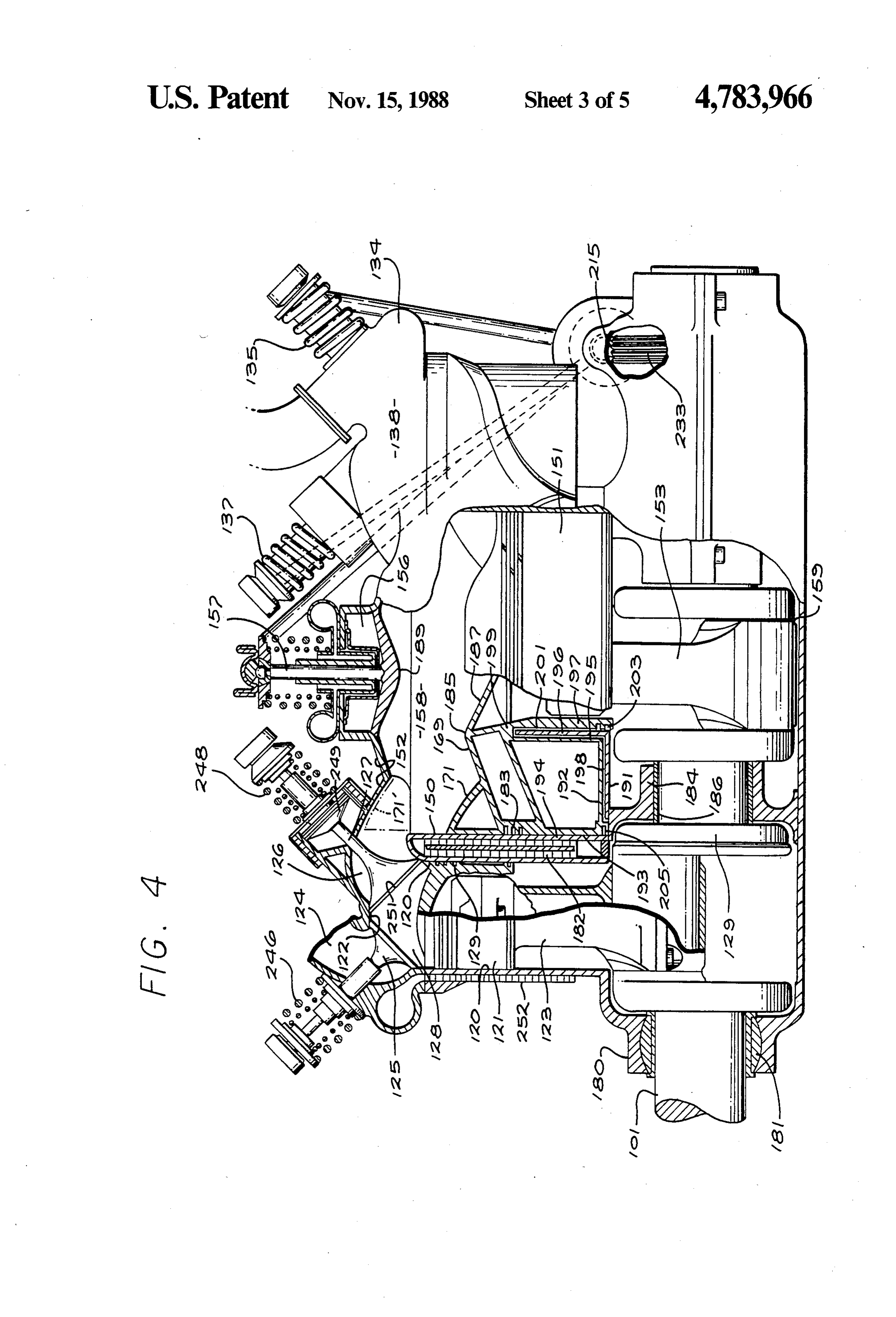
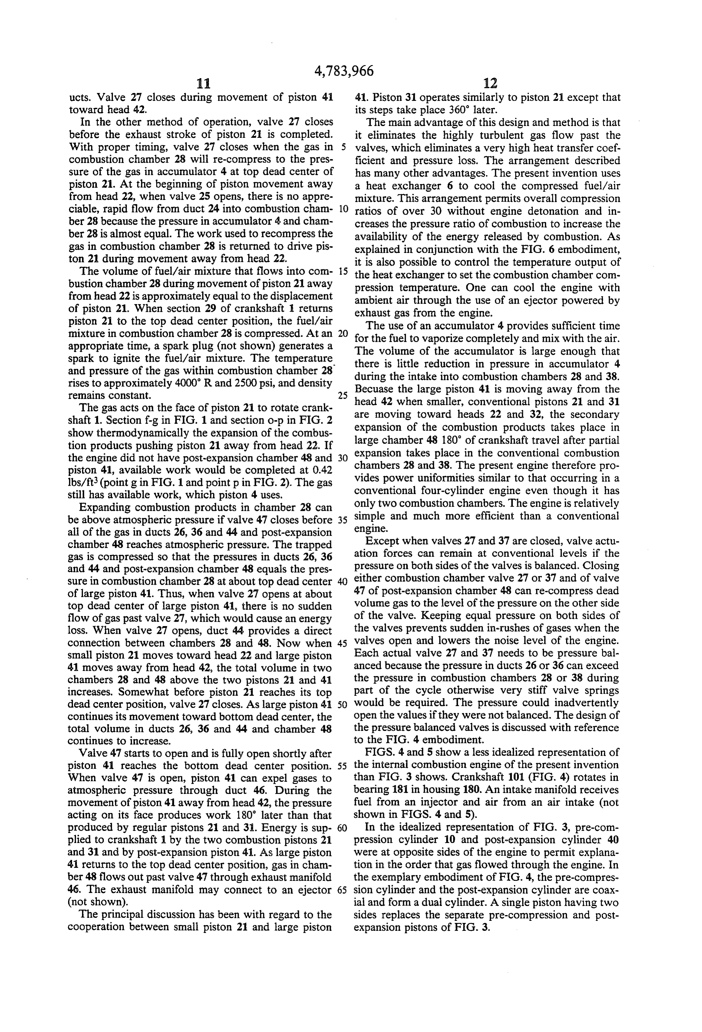
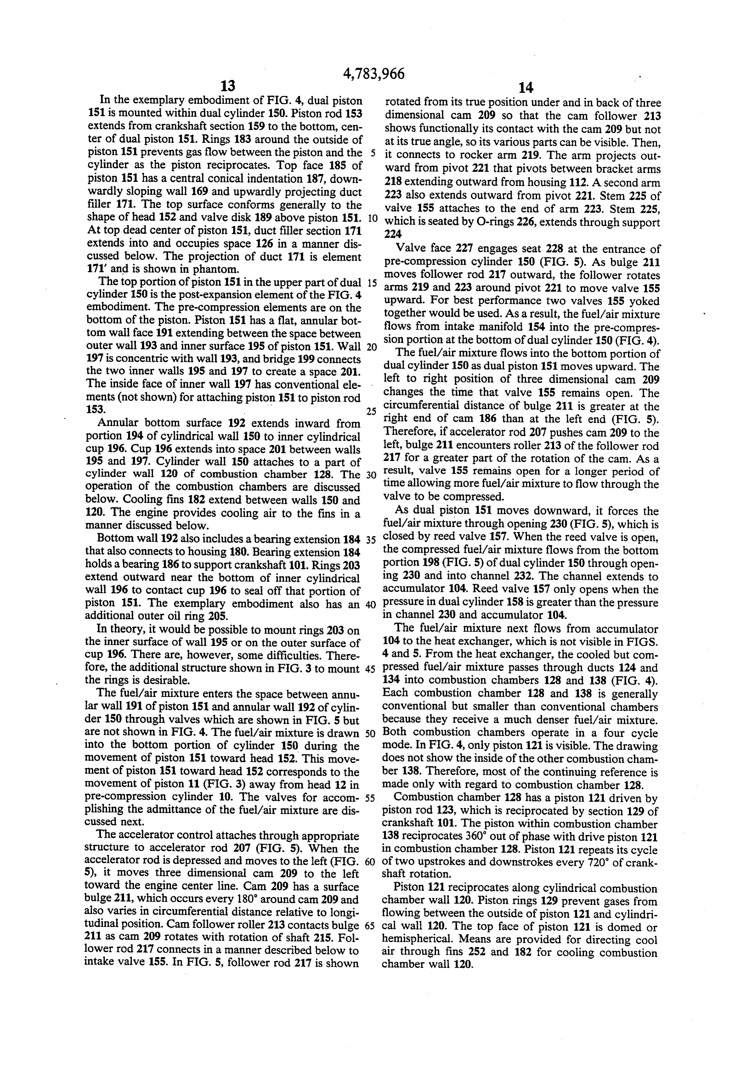
Valve 47 starts to open and is fully open shortly after FIGS. 4 and 5 show a less idealized representation of piston 41 reaches the bottom dead center position. 55 the internal combustion engine of the present invention When valve 47 is open, piston 41 can expel gases to than FIG. 3 shows. Crankshaft 101 (FIG. 4) rotates in atmospheric pressure through duct 46. During the bearing 181 in housing 180. An intake manifold receives movement of piston 41 away from head 42, the pressure fuel from an injector and air from an air intake (not acting on its face produces work 180' later than that shown in FIGS. 4 and 5).
produced by regular pistons 21 and 31. Energy is sup 60 In the idealized representation of FIG. 3, pre-com plied to crankshaft 1 by the two combustion pistons 21 pression cylinder 10 and post-expansion cylinder 40 and 31 and by post-expansion piston 41. As large piston were at opposite sides of the engine to permit explana 41 returns to the top dead center position, gas in cham tion in the order that gas flowed through the engine. In ber 48 flows out past valve 47 through exhaust manifold the exemplary embodiment of FIG. 4, the pre-compres 46. The exhaust manifold may connect to an ejector 65 sion cylinder and the post-expansion cylinder are coax (not shown). ial and form a dual cylinder. A single piston having two The principal discussion has been with regard to the sides replaces the separate pre-compression and post cooperation between small piston 21 and large piston expansion pistons of FIG. 3.
Page 13
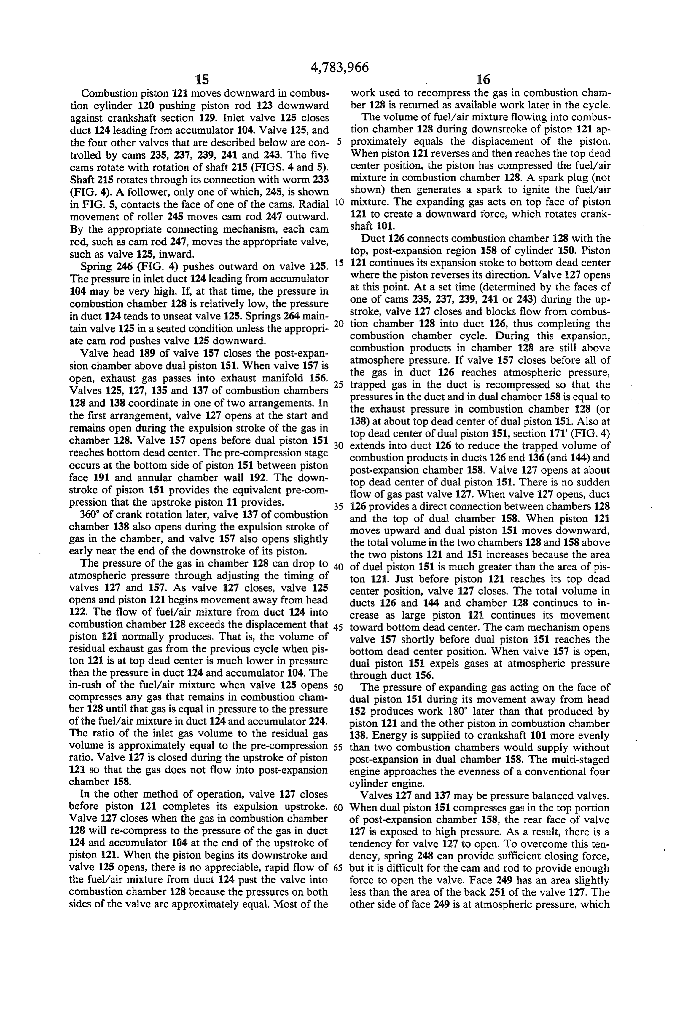
In the exemplary embodiment of FIG. 4, dual piston rotated from its true position under and in back of three 151 is mounted within dual cylinder 150. Piston rod 153 dimensional cam 209 so that the cam follower 213 extends from crankshaft section 159 to the bottom, cen shows functionally its contact with the cam 209 but not ter of dual piston 151. Rings 183 around the outside of at its true angle, so its various parts can be visible. Then, piston 151 prevents gas flow between the piston and the it connects to rocker arm 219. The arm projects out cylinder as the piston reciprocates. Top face 185 of ward from pivot 221 that pivots between bracket arms piston 151 has a central conical indentation 187, down 218 extending outward from housing 112. A second arm wardly sloping wall 169 and upwardly projecting duct filler 171. The top surface conforms generally to the 223 also extends outward from pivot 221. Stem 225 of valve 155 attaches to the end of arm 223. Stem 225, shape of head 152 and valve disk 189 above piston 151. O which is seated by O-rings 226, extends through support At top dead center of piston 151, duct filler section 171 224 extends into and occupies space 126 in a manner dis Valve face 227 engages seat 228 at the entrance of cussed below. The projection of duct 171 is element pre-compression cylinder 150 (FIG. 5). As bulge 211 171' and is shown in phantom. moves follower rod 217 outward, the follower rotates The top portion of piston 151 in the upper part of dual 15 arms 219 and 223 around pivot 221 to move valve 155 cylinder 150 is the post-expansion element of the FIG. 4 upward. For best performance two valves 155 yoked embodiment. The pre-compression elements are on the together bottom of the piston. Piston 151 has a flat, annular bot flows from intake manifold 154 intothethefuel/air would be used. As a result, mixture tom wall face 191 extending between the space between sion portion at the bottom of dual cylinder pre-compres
outer wall 193 and inner surface 195 of piston 151. Wall 20 The fuel/air mixture flows into the bottom portion of 197 is concentric with wall 193, and bridge 199 connects the two inner walls 195 and 197 to create a space 201. dual cylinder 150 as dual piston 151 moves upward. The left to right position of three dimensional cam 209
The inside face of inner wall 197 has conventional ele ments changes the time that valve 155 remains open. The (not shown) for attaching piston 151 to piston rod circumferential 153. 25 distance of bulge 211 is greater at the Annular bottom surface 192 extends inward from right end of cam 186 than at the left end (FIG. 5). portion 194 of cylindrical wall 150 to inner cylindrical Therefore, if accelerator rod 207 pushes cam 209 to the cup 196. Cup 196 extends into space 201 between wallsleft, bulge 211 encounters roller 213 of the follower rod 195 and 197. Cylinder wall 150 attaches to a part of 217 for a greater part of the rotation of the cam. As a cylinder wall 120 of combustion chamber 128. The 30 result, valve 155 remains open for a longer period of operation of the combustion chambers are discussed time allowing more fuel/air mixture to flow through the below. Cooling fins 182 extend between walls 150 and valve to be compressed.
120. The engine provides cooling air to the fins in a As dual piston 151 moves downward, it forces the manner discussed below. fuel/air mixture through opening 230 (FIG. 5), which is Bottom wall 192 also includes a bearing extension 184 35 closed by reed valve 157. When the reed valve is open, that also connects to housing 180. Bearing extension 184 the compressed fuel/air mixture flows from the bottom holds a bearing 186 to support crankshaft 101. Rings 203 portion 198 (FIG. 5) of dual cylinder 150 through open extend outward near the bottom of inner cylindrical ing 230 and into channel 232. The channel extends to wall 196 to contact cup 196 to seal off that portion of accumulator 104. Reed valve 157 only opens when the piston 151. The exemplary embodiment also has an 40 pressure in dual cylinder 158 is greater than the pressure additional outer oil ring 205. in channel 230 and accumulator 104. In theory, it would be possible to mount rings 203 on The fuel/air mixture next flows from accumulator the inner surface of wall 195 or on the outer surface of 104 to the heat exchanger, which is not visible in FIGS. cup 196. There are, however, some difficulties. There 4 and 5. From the heat exchanger, the cooled but com fore, the additional structure shown in FIG. 3 to mount 45 pressed fuel/air mixture passes through ducts 124 and the rings is desirable. 134 into combustion chambers 128 and 138 (FIG. 4). The fuel/air mixture enters the space between annu Each combustion chamber 128 and 138 is generally lar wall 191 of piston 151 and annular wall 192 of cylin conventional but smaller than conventional chambers der 150 through valves which are shown in FIG. 5 but because they receive a much denser fuel/air mixture. are not shown in FIG. 4. The fuel/air mixture is drawn 50 Both combustion chambers operate in a four cycle into the bottom portion of cylinder 150 during the mode. In FIG.4, only piston 121 is visible. The drawing movement of piston 151 toward head 152. This move does not show the inside of the other combustion cham ment of piston 151 toward head 152 corresponds to the ber 138. Therefore, most of the continuing reference is movement of piston 11 (FIG. 3) away from head 12 in made only with regard to combustion chamber 128. pre-compression cylinder 10. The valves for accom 55 Combustion chamber 128 has a piston 121 driven by plishing the admittance of the fuel/air mixture are dis piston rod 123, which is reciprocated by section 129 of cussed next. crankshaft 101. The piston within combustion chamber The accelerator control attaches through appropriate 138 reciprocates 360 out of phase with drive piston 121 structure to accelerator rod 207 (FIG. 5). When the in combustion chamber 128. Piston 121 repeats its cycle accelerator rod is depressed and moves to the left (FIG. 60 of two upstrokes and downstrokes every 720 of crank 5), it moves three dimensional cam 209 to the left shaft rotation.
toward the engine center line. Cam 209 has a surface Piston 121 reciprocates along cylindrical combustion bulge 211, which occurs every 180' around cam 209 and chamber wall 120. Piston rings 129 prevent gases from also varies in circumferential distance relative to longi flowing between the outside of piston 121 and cylindri tudinal position. Cam follower roller 213 contacts bulge 65 cal wall 120. The top face of piston 121 is domed or 211 as can 209 rotates with rotation of shaft 215. Fol hemispherical. Means are provided for directing cool lower rod 217 connects in a manner described below to air through fins 252 and 182 for cooling combustion intake valve 155. In FIG. 5, follower rod 217 is shown chamber wall 120.
Page 14
Combustion piston 121 moves downward in combus work used to recompress the gas in combustion cham tion cylinder 120 pushing piston rod 123 downward ber 128 is returned as available work later in the cycle. against crankshaft section 129. Inlet valve 125 closes The volume of fuel/air mixture flowing into combus duct 124 leading from accumulator 104. Valve 125, and tion chamber 128 during downstroke of piston 121 ap the four other valves that are described below are con proximately equals the displacement of the piston. trolled by cams 235, 237, 239, 241 and 243. The five When piston 121 reverses and then reaches the top dead cams rotate with rotation of shaft 215 (FIGS. 4 and 5). center position, the piston has compressed the fuel/air Shaft 215 rotates through its connection with worm 233 mixture in combustion chamber 128. A spark plug (not (FIG. 4). A follower, only one of which, 245, is shown shown) then generates a spark to ignite the fuel/air in FIG. 5, contacts the face of one of the cams. Radial 10 mixture. The expanding gas acts on top face of piston movement of roller 245 moves can rod 247 outward. 12 to create a downward force, which rotates crank By the appropriate connecting mechanism, each cam shaft 101.
rod, such as cam rod 247, moves the appropriate valve, Duct 126 connects combustion chamber 28 with the such as valve 125, inward. top, post-expansion region 158 of cylinder 150. Piston Spring 246 (FIG. 4) pushes outward on valve 125. 15 121 continues its expansion stoke to bottom dead center The pressure in inlet duct 124 leading from accumulator where the piston reverses its direction. Valve 127 opens 104 may be very high. If, at that time, the pressure in at this point. At a set time (determined by the faces of
combustion chamber 128 is relatively low, the pressure stroke, valve 127 closes and blocks flow from combus in duct 124 tends to unseat valve 125. Springs 264 main tion chamber 128 into duct 126, thus completing the tain valve 125 in a seated condition unless the appropri combustion chamber cycle. During this expansion, ate cam rod pushes valve 125 downward. combustion products in chamber 128 are still above Valve head 189 of valve 157 closes the post-expan atmosphere sion chamber above dual piston 151. When valve 157 is the gas in pressure. If valve 157 closes before all of open, exhaust gas passes into exhaust manifold 156. 25 trapped gas in the ductreaches duct 126 atmospheric pressure,
Valves 125, 127, 135 and 137 of combustion chambers pressures in the duct and in dual chamber 158sois that is recompressed equal the
128 and 138 coordinate in one of two arrangements. In the exhaust pressure in combustion chamber 128 (or the first arrangement, valve 127 opens at the start and 138) at about top dead center of dual piston 151. Also at remains open during the expulsion stroke of the gas in chamber 128. Valve 157 opens before dual piston 151 30 top dead center of dual piston 151, section 171' (FIG. 4) extends into duct 126 to reduce the trapped volume of reaches bottom dead center. The pre-compression stage combustion products inducts 126 and 136 (and 144) and occurs at the bottom side of piston 151 between piston post-expansion chamber 158. Valve 127 opens at about face 191 and annular chamber wall 192. The down top dead center of dual piston 15. There is no sudden stroke of piston 151 provides the equivalent pre-com flow of gas past valve 127. When valve 127 opens, duct pression that the upstroke piston 11 provides. 35 126 provides a direct connection between chambers 128 360 of crank rotation later, valve 137 of combustion chamber 138 also opens during the expulsion stroke of and the top of dual chamber 158. When piston 121 moves upward and dual piston 151 moves downward, gas in the chamber, and valve 157 also opens slightly the total volume in the two chambers 128 and 158 above early near the end of the downstroke of its piston. the two pistons 121 and 151 increases because the area The pressure of the gas in chamber 128 can drop to 40 of duel piston 151 is much greater than the area of pis atmospheric pressure through adjusting the timing of ton 121. Just before piston 121 reaches its top dead valves 127 and 157. As valve 127 closes, valve 125 center position, valve 127 closes. The total volume in opens and piston 121 begins movement away from head ducts 126 and 144 and chamber 128 continues to in 122. The flow of fuel/air mixture from duct 124 into crease as large piston 121 continues its movement combustion chamber 128 exceeds the displacement that 45 toward bottom dead center. The cam mechanism opens piston 21 normally produces. That is, the volume of valve 157 shortly before dual piston 151 reaches the residual exhaust gas from the previous cycle when pis bottom dead center position. When valve 157 is open, ton 121 is at top dead center is much lower in pressure dual piston 151 expels gases at atmospheric pressure than the pressure in duct 124 and accumulator 104. The through duct 156.
in-rush of the fuel/air mixture when valve 125 opens SO The pressure of expanding gas acting on the face of compresses any gas that remains in combustion cham dual piston 151 during its movement away from head ber 128 until that gas is equal in pressure to the pressure 152 produces work 180' later than that produced by of the fuel/air mixture induct 124 and accumulator 224. piston 121 and the other piston in combustion chamber The ratio of the inlet gas volume to the residual gas 138. Energy is supplied to crankshaft 101 more evenly volume is approximately equal to the pre-compression 55 than two combustion chambers would supply without ratio. Valve 127 is closed during the upstroke of piston post-expansion in dual chamber 158. The multi-staged 121 so that the gas does not flow into post-expansion engine approaches the evenness of a conventional four chamber 158. cylinder engine.
In the other method of operation, valve 127 closes Valves 127 and 137 may be pressure balanced valves. before piston 121 completes its expulsion upstroke. 60 When dual piston 151 compresses gas in the top portion Valve 127 closes when the gas in combustion chamber of post-expansion chamber 158, the rear face of valve 128 will re-compress to the pressure of the gas in duct 127 is exposed to high pressure. As a result, there is a 124 and accumulator 104 at the end of the upstroke of tendency for valve 127 to open. To overcome this ten piston 121. When the piston begins its downstroke and dency, spring 248 can provide sufficient closing force, valve 125 opens, there is no appreciable, rapid flow of 65 but it is difficult for the cam and rod to provide enough the fuel/air mixture from duct 124 past the valve into force to open the valve. Face 249 has an area slightly combustion chamber 128 because the pressures on both less than the area of the back 251 of the valve 127. The sides of the valve are approximately equal. Most of the other side of face 249 is at atmospheric pressure, which
Page 15
provides a force that reduces the force that spring 248 376 and into second accumulator 384 when the pressure would have to provide. Pressurized gas passes through in pre-compression chamber 378 exceeds the pressure in opening 250 and pressurizes face 249 to balance approx second accumulator 384. Valves 375 and 377 are similar imately the differential pressure load in the opposite in operation and in related control structure to valves direction. 315 and 317 of the first pre-compression stage, and all of Finned cooling passages, such as passage 252, are them are similar to the respective valves 15 and 17 of provided on the outside of cylindrical walls 120 of the the single pre-compression stage in the FIG. 3 embodi combustion chambers. Finned cooling passage 252 is Inent.
representative. Cooling can be provided at other loca- - The high pressure working fluid them passes through tions where it is necessary. Air for cooling can come 10 heat exchanger 386 where it can then flow to combus from several sources. The exhaust gas in exhaust mani tion chambers 328 and 338. Heat exchanger 386 is fold 156 (FIG. 4) can drive a blower, ejector or other shown in the exemplary embodiment as a recuperator. air flow device. The crankshaft may also be connected The recuperator has a low pressure, hot fluid bypass to an air compressor.
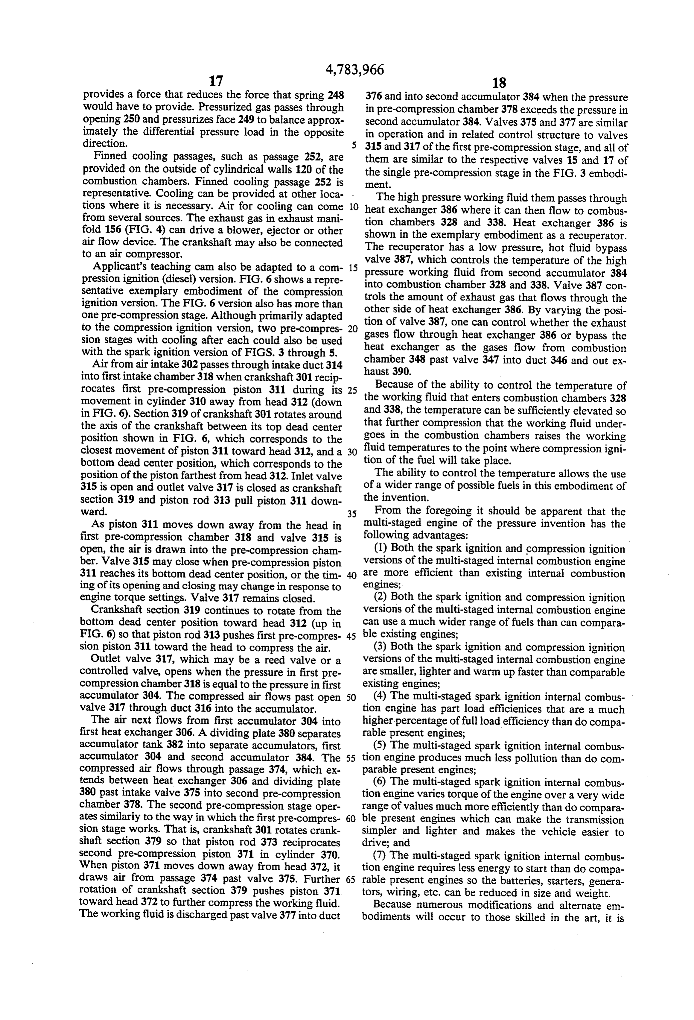
Applicant's teaching cam also be adapted to a com 15 pressure working controls valve 387, which the temperature of the high pression ignition (diesel) version. FIG. 6 shows a repre into combustion chamber 328 second fluid from accumulator 384 and 338. Valve 387 con sentative exemplary embodiment of the compression trols the amount of exhaust gas that flows through the ignition version. The FIG. 6 version also has more than other one pre-compression stage. Although primarily adapted tion ofside of heat exchanger 386. By varying the posi valve 387, one can control whether the exhaust to the compression ignition version, two pre-compres 20 gases flow through heat exchanger 386 or bypass the sion stages with cooling after each could also be used heat exchanger as the gases flow from combustion with the spark ignition version of FIGS. 3 through 5. chamber 348 past valve 347 into duct 346 and out ex Air from air intake 302 passes through intake duct 314 into first intake chamber 318 when crankshaft 301 recip haust 390.
rocates first pre-compression piston 311 during its 25 Because of the ability to control the temperature of movement in cylinder 310 away from head 312 (down the working fluid that enters combustion chambers 328 in FIG. 6). Section 319 of crankshaft 301 rotates around and 338, the temperature can be sufficiently elevated so the axis of the crankshaft between its top dead center that further compression that the working fluid under position shown in FIG. 6, which corresponds to the goes in the combustion chambers raises the working closest movement of piston 311 toward head 312, and a 30 fluid temperatures to the point where compression igni bottom dead center position, which corresponds to the tion of the fuel will take place.
position of the piston farthest from head 312. Inlet valve The ability to control the temperature allows the use 315 is open and outlet valve 317 is closed as crankshaft of a wider range of possible fuels in this embodiment of the invention.
section 319 and piston rod 313 pull piston 311 down ward. 35 From the foregoing it should be apparent that the As piston 311 moves down away from the head in multi-staged engine of the pressure invention has the first pre-compression chamber 318 and valve 315 is following advantages:
open, the air is drawn into the pre-compression cham (1) Both the spark ignition and compression ignition ber. Valve 315 may close when pre-compression piston versions of the multi-staged internal combustion engine 311 reaches its bottom dead center position, or the tim are more efficient than existing internal combustion ing of its opening and closing may change in response to engines;
engine torque settings. Valve 317 remains closed. (2) Both the spark ignition and compression ignition Crankshaft section 319 continues to rotate from the versions of the multi-staged internal combustion engine bottom dead center position toward head 312 (up in can use a much wider range of fuels than can compara FIG. 6) so that piston rod 313 pushes first pre-compres 45 ble existing engines;
sion piston 311 toward the head to compress the air. (3) Both the spark ignition and compression ignition Outlet valve 317, which may be a reed valve or a versions of the multi-staged internal combustion engine controlled valve, opens when the pressure in first pre are smaller, lighter and warm up faster than comparable compression chamber 318 is equal to the pressure in first existing engines;
accumulator 304. The compressed air flows past open 50 (4) The multi-staged spark ignition internal combus valve 317 through duct 316 into the accumulator. tion engine has part load efficienices that are a much The air next flows from first accumulator 304 into higher percentage of full load efficiency than do compa first heat exchanger 306. A dividing plate 380 separates rable present engines;
accumulator tank 382 into separate accumulators, first (5) The multi-staged spark ignition internal combus accumulator 304 and second accumulator 384. The 55 tion engine produces much less pollution than do com compressed air flows through passage 374, which ex parable present engines;
tends between heat exchanger 306 and dividing plate (6) The multi-staged spark ignition internal combus 380 past intake valve 375 into second pre-compression tion engine varies torque of the engine over a very wide chamber 378. The second pre-compression stage oper range of values much more efficiently than do compara ates similarly to the way in which the first pre-compres 60 ble present engines which can make the transmission sion stage works. That is, crankshaft 301 rotates crank simpler and lighter and makes the vehicle easier to shaft section 379 so that piston rod 373 reciprocates drive; and second pre-compression piston 371 in cylinder 370. (7) The multi-staged spark ignition internal combus When piston 371 moves down away from head 372, it tion engine requires less energy to start than do compa draws air from passage 374 past valve 375. Further 65 rable present engines so the batteries, starters, genera rotation of crankshaft section 379 pushes piston 371 tors, wiring, etc. can be reduced in size and weight. toward head 372 to further compress the working fluid. Because numerous modifications and alternate em The working fluid is discharged past valve 377 into duct bodiments will occur to those skilled in the art, it is
Page 16
intended that the invention be limited only in terms of ber is located on opposite sides of the dual cylinder with the appended claims. respect to the other.
I claim: 8. An engine as set forth in claim 1, wherein the 1. A multi-staged internal combustion engine, com working fluid is a fuel/air mixture.
prising: 5 9. A multi-staged internal combustion engine com means for compressing a working fluid; prising:
accumulator means connected to the compressing driven means mounted for rotation in the engine: means for receiving and storing the compressed pre-compression means including a pre-compression working fluid; cylinder and a pre-compression piston in the pre means for cooling the compressed working fluid of 10 compression cylinder, piston connecting means the accumulator means; between the pre-compression piston and the driven means for receiving the cooled working fluid from means, the pre-compression cylinder receiving a the accumulator means, further compressing the fuel/air mixture and compressing the fuel/air mix working fluid, and combusting the working fluid to 15 ture;
drive the engine; and accumulator means connected to the pre-compres means for utilizing exhaust from the combusting sion cylinder for receiving the compressed fuel/air means to drive the engine through expansion of the mixture;
exhaust. heat exchanger means for cooling the fuel/air mixture 2. An engine as set forth in claim 1, wherein the of the accumulator means;
means for utilizing exhaust from the combusting means combustion means including combustion chamber to drive the engine through expansion of the exhaust, means and a combustion piston in the combustion drive the means for compressing the working fluid. chamber means, rod connecting means between the 3. An engine as set forth in claim 1, including drive combustion piston and the driven means, the com means mounted for rotation in the engine, and wherein 25 bustion chamber means being connected to the heat the means for compressing a working fluid includes a exchanger means for receiving the fuel/air mixture, pre-compression cylinder and a pre-compression piston the combustion piston compressing the fuel/air in the pre-compression cylinder, and connecting means mixture which is then ignited to create combustion between the pre-compression cylinder and the driven products which expand to drive the combustion means, wherein the pre-compression cylinder receives 30 piston and thereby rotate the driven means; and the working fluid which is compressed therein by the post-expansion means including a post-expansion cyl pre-compression piston. inder and a post-expansion piston in the post expan 4. An engine as set forth in claim 3, wherein the sion cylinder, and means for attaching the post means for utilizing exhaust from the combustion means expansion piston to the driven means, the post to drive the engine through expansion of the exhaust, is expansion cylinder receiving combustion products includes a post-expansion cylinder and a post-expansion at elevated pressure from the combustion chamber piston in the post-expansion cylinder, and means for means, wherein the pressure of the combustion attaching the post-expansion piston to the driven means, products pushes the post-expansion piston to drive the post-expansion cylinder receiving combustion prod the driven means.
ucts at elevated pressure from the combusting means, 40 10. An engine as set forth in claim 9, wherein the wherein the pressure of the combustion products pushes surface area of a combustion piston is a small fraction of the post-expansion piston to drive the driven means. the surface area of the post-expansion piston. 5. An engine as set forth in claim 1, including driven 11. An engine as set forth in claim 9, further compris means mounted for rotation in the engine, and wherein ing an intake valve between the heat exchanger means the combusting means includes combustion chamber 45 and the combustion chamber means, an outlet valve means including a combustion chamber and a combus between the combustion chamber means and the post tion piston in the combustion chamber, and rod con expansion cylinder, and a first can means operably necting means between the combustion piston and the connected to the driven means for opening the outlet driven means, wherein the combustion piston com valve during a portion of the movement of the combus presses the working fluid which is then ignited to create 50 tion piston.
combustion products which expand to drive the com 12. An engine as set forth in claim 11, further con bustion piston and thereby drive the driven means. prising a post-expansion valve in the post-expansion 6. An engine as set forth in claim 5, wherein the cylinder alternatively closing and opening the post means for compressing the working fluid includes a expansion cylinder to the exhaust, and a second can pre-compression cylinder and a pre-compression piston 55 means operably connected to the post-expansion valve in the pre-compression cylinder, and wherein the means for opening the post-expansion valve means during a for utilizing exhaust from the combusting means to portion of the movement of the post-expansion piston. drive the engine through expansion of the exhaust in 13. An engine as set forth in claim 9, further compris cludes a post-expansion cylinder and a post-expansion ing an intake valve between the heat exchanger means piston in the post-expansion cylinder, wherein the pre- 60 and the combustion chamber means, an outlet valve compression cylinder and the post-expansion cylinder between the combustion chamber means and the post are co-axial and form a dual cylinder, the pre-compres expansion cylinder, and first cam means operably con sion piston comprising one side of a dual piston within nected to the driven means, the amount of the fuel/air the dual cylinder, the post-expansion piston comprising mixture flowing from the heat exchanger means into the the other side of the dual piston within the dual cylin- 65 combustion chamber means adding to any combustion der. products in the combustion chamber means so that the 7. An engine as set forth in claim 6, including two total amount of the fuel/air mixture and the combustion combustion chambers, wherein each combustion cham products exceeds the displacement that the combustion
Page 17
piston means would normally produce in the combus means to the pre-compression cylinder and an open tion chamber means. condition permitting the fuel/air mixture to flow 14. An engine as set forth in claim 9, wherein the from the intake means to the pre-compression cyl pre-compression cylinder and the post-expansion cylin inder.
der are co-axial and form a dual cylinder, the pre-com 5 21. An engine as set forth in claim 20, further com pression piston comprising one side of a dual piston prising pre-compressor exit valve means between the within the dual cylinder, the post-expansion piston com pre-compression cylinder and the accumulator means prising the other side of the dual piston within the dual for alternately blocking the fuel/air mixture from flow cylinder. ing from the pre-compression cylinder to the accumula 15. An engine as set forth in claim 14, wherein the O tor means and permitting the fuel/air mixture to flow combustion chamber means comprises a pair of combus from the pre-compression cylinder to the accumulator tion chambers, each combustion chamber being on op means, wherein the exit valve means is a flexure-close posite sides of the dual cylinder, wherein the piston in off valve for causing the fuel/air mixture to flow into the dual cylinder moves in the opposite direction to the the accumulator means only when the pressure in the pistons in the combustion chambers. 15 pre-compression cylinder exceeds the pressure in the 16. An engine as set forth in claim 15, wherein the accumulator means.
fuel/air mixture in each of the combustion chambers is 22. An engine as set forth in claim 20, wherein the ignited during every 720 of rotation of the driven intake valve means is a flexure-close off valve. means, each combustion piston being 360 out-of-phase 23. An engine as set forth in claim 9, further compris with each other. 20 1ng:
17. An engine as set forth in claim 9, further compris fuel/air mixing means connected to the pre-compres ing a duct extending between the combustion chamber sion cylinder;
means and the post-expansion cylinder through which intake means between the fuel/air mixing means and gas can flow, outlet valve means closing the duct to the pre-compression cylinder for conveying fuel prevent flow between the combustion chamber means 25 /air mixture from the fuel/air mixing means to the and the post-expansion cylinder, and valve cam means pre-compression cylinder; for opening the outlet valve, the outlet valve having a intake valve means between the intake means and the pressure balancing surface responding to the pressure in pre-compression cylinder for alternately blocking the duct to compensate for pressure on other parts of fuel/air mixture from flowing from the intake the outlet valve tending to open the outlet valve. 30 means to the pre-compression cylinder and permit 18. An engine as set forth in claim 9, further compris ting the fuel/air mixture to flow from the intake ing a duct extending between the combustion chamber means to the pre-compression cylinder; and means and the post-expansion cylinder through which adjustable cam means and follower means extending gas can flow, outlet valve means closing the duct to between the adjustable cam means and the intake prevent flow between the combustion chamber means 35 valve means for adjusting the timing that the intake and the post-expansion cylinder, and valve cam means valve means is in its open condition, wherein the for opening the outlet valve, the driven means driving adjustable cam means is connected to an accelera the combustion piston through a first of two movements tor means to adjust the timing that the intake valve to exhaust combustion products into the duct, the valve means is in the open condition in response to cam means closing the outlet valve during the second of 40 changes in the setting of the accelerator means. the two movements of the combustion piston to recom 24. A multi-staged internal combustion engine, com press combustion products to approximately the pres prising:
sure of the fuel/air mixture in the accumulator means. means for compressing a working fluid, including a 19. An engine as set forth in claim 18, further com pre-compression cylinder and a pre-compression prising an exhaust duct exhausting the combustion 45 piston in the pre-compression cylinder; products from the post-expansion means, post-expan means for cooling the working fluid which has exited sion outlet valve means closing the exhaust duct to the compressing means;
prevent flow from the post-expansion means, and an combustion chamber means for receiving working exhaust valve cam means for opening the post-expan fluid previously conditioned by the compressing sion outlet valve at each engine rotation, the exhaust 50 means and cooling means, further compressing the valve can means closing the post-expansion outlet working fluid, and combusting the working fluid to valve to permit recompression of the combustion prod drive the engine;
lucts within the post-expansion means to approximately means for utilizing exhaust from the combustion the pressure of the combustion products in the combus chamber means to drive the engine through expan tion chamber at the time the outlet valve means be 55 sion of the exhaust, including a post-expansion tween the combustion chamber and post-expansion cylinder and a post-expansion piston in the post means opens. expansion cylinder, wherein the pre-compression 20. An engine as set forth in claim 9, further compris cylinder and the post-expansion cylinder are co ing: axial and form a dual cylinder, the pre-compression fuel/air mixing means; 60 piston comprising one side of a dual piston within intake means between the fuel/air mixing means and the dual cylinder, the post-expansion piston com the pre-compression cylinder for conveying the prising the other side of the dual piston within the fuel/air mixture from the fuel/air mixing means to dual cylinder; and the pre-compression cylinder; and driven means mounted for rotation in the engine, intake valve means between the intake means and the 65 wherein the combustion chamber means includes a pre-compression cylinder, the intake valve means combustion chamber and a combustion piston in alternating between a blocking condition for block the combustion chamber, and rod connecting ing fuel/air mixture from flowing from the intake means between the combustion piston and the
Page 18
driven means, wherein the combustion piston con a heat exchanger connected by passage means to the presses the working fluid which is then ignited to pre-compression cylinder for cooling the fuel/air create combustion products which expand to drive mixture;
the combustion piston and thereby drive the driven intake duct means extending from the heat exchanger e2S. to the combustion chambers;
25. An engine as set forth in claim 24, including two a post-expansion piston mounted for reciprocation in combustion chambers, wherein each combustion cham a post-expansion cylinder, third connecting means ber is located on opposite sides of the dual cylinder with for connecting the post-expansion piston to the respect to the other. drive means for reciprocating the post-expansion 26. An internal combustion engine, comprising: 10 piston 180° out-of-phase with the combustion pis a pre-compression cylinder including a pre-compres tons;
sion cylinder head and having a pre-compression post-expansion duct means connecting the combus piston therein; tion chambers with the post-expansion cylinder; drive means connected to the pre-compression piston 15 outlet and for reciprocating the pre-compression piston be valve means for each combustion chamber in tween movement toward and away from the pre the post-expansion duct means for alternatively compression cylinder head, the pre-compression closing or opening the post-expansion duct means cylinder receiving a fuel/air mixture during the and, control means for opening the outlet valve movement of the pre-compression piston away means when the combustion products are still ex from pre-compression cylinder head, the pre-com 20 panding in the combustion chamber so that some of pression piston compressing the fuel/air mixture; the expansion of the combustion products takes an accumulator connected to the pre-compression place in the post-expansion cylinder to move the cylinder and receiving the compressed fuel/air post-expansion piston against its connecting means to drive the drive means.
mixture from the pre-compression cylinder; 25 28. An internal combustion engine as set forth in a heat exchanger attached to the accumulator for claim 27, wherein there are two combustion chambers, cooling the fuel/air mixture from the accumulator; each combustion chamber being located on opposite a plurality of combustion chambers each including a sides of the post-expansion chamber. combustion chamber head, and a combustion pis 29. An internal combustion engine as set forth in ton in each combustion chamber connected to the 30 claim 27, wherein the pre-compression cylinder and the drive means, each combustion piston reciprocating post-expansion cylinder are co-axial and form a dual between movement toward and away from the cylinder, the pre-compression piston comprising one respective combustion chamber head, each com side of a dual piston within the dual cylinder, the post bustion chamber being connected to the heat ex expansion piston comprising the other side of the dual changer for receiving the fuel/air mixture during a 35 piston within the dual cylinder.
movement of the respective combustion piston 30. A multi-stage internal combustion engine, com away from the combustion chamber head, the com prising:
bustion piston compression the fuel/air mixture combustion chamber means including at least two which is subsequently ignited to create combustion combustion chambers each having a combustion products which expand to drive the combustion piston reciprocating within a respective combus piston from the combustion chamber head to drive tion cylinder, wherein fuel is injected into the com the drive means; and bustion chambers;
a post-expansion cylinder, and a post-expansion pis drive means in the engine connected to the combus ton connected to the drive means and positioned 45 tion pistons for converting reciprocating motion of for reciprocating movement within the post-expan the pistons into rotary motion of the drive means; sion cylinder, wherein the post-expansion cylinder first pre-compression means driven by the drive receives exhaust gases from the combustion cham means for compressing air prior to its being drawn bers to drive the drive means. into the combustion chamber means; 27. An internal combustion engine, comprising: first accumulator means connected to the first pre at least two combustion chambers each having a com 50 compression means by first duct means, the first bustion piston reciprocating toward and away from accumulator means storing compressed air at an a closed off end; elevated pressure;
drive means in the engine and connecting means be first heat exchanger means for cooling the air exiting tween the combustion pistons and the drive means 55 the first accumulator means; for converting reciprocating motion of the pistons second pre-compression means connected by second into rotary motion of the drive means; pre-compression intake means to the first accumu a pre-compression piston mounted for reciprocation lator means, the second pre-compression means in a pre-compression cylinder, the pre-compression being driven by the drive means for further com pressing the air;
cylinder having a closed head end, second connect 60 second accumulator means connected by second duct ing means between the pre-compression piston and means to the second pre-compression means, the the drive means for reciprocating the pre-compres second accumulator means storing the further sion piston in the pre-compression cylinder compressed air at an elevated pressure; whereby the piston draws a fuel/air mixture into second heat exchanger means connected by second the pre-compression cylinder when the pre-com 65 passage means to the second accumulator means, pression piston moves away from the head and the second heat exchanger means heating the air; compresses the fuel/air mixture when it moves intake duct means extending from the second heat toward the head; exchanger means to the combustion chamber
Page 19
means for introducing the further compressed air connected to engine drive output means, each com into the combustion chambers; and bustion piston reciprocating between movement post-expansion means connected by post-expansion toward and away from the respective combustion duct means to the combustion chamber means, the chamber head, each combustion chamber being post expansion means utilizing exhaust from the fluidly connected with the cooling means for re combustion chamber means to drive the drive ceiving the working fluid during a movement of means through expansion of the exhaust; the respective combustion piston away from the wherein the exhaust from the post-expansion means combustion chamber head, the combustion piston provides means for heating the air of the second compressing the working fluid which is subse heat exchanger means. 10 quently ignited to create combustion products 31. An engine as set forth in claim 30, including ad which expand to drive the combustion piston from justable valve means for controlling the flow of exhaust the combustion chamber head to drive the engine from the post-expansion means through the second heat drive output means; and exchanger means. means for utilizing exhaust from the combustion 32. A method of operation of an internal combustion 5 chamber means to drive the engine through expan engine, the steps comprising: sion of the exhaust.
compressing a working fluid; 38. A multi-staged internal combustion engine, com temporarily storing the working fluid that was com prising:
pressed; means for compressing a working fluid; cooling the temporarily stored, compressed working 20 means for cooling the working fluid which has exited fluid; the compressing means;
further compressing the working fluid within a com combustion chamber means for receiving working bustion chamber, igniting the further compressed fluid previously conditioned by the compressing working fluid and expanding the products of com means and cooling means, further compressing the bustion against a piston in the combustion chamber 25 working fluid, and combusting the working fluid to to drive the engine; and drive the engine, including a plurality of combus transferring a portion of the expanding combustion tion chambers each including a combustion cham products to a post-expansion cylinder to expand ber head, and a combustion piston in each combus against a post-expansion piston in the post-expan tion chamber connected to engine drive output sion cylinder to further drive the engine. 30 means, each combustion piston reciprocating be 33. The method of claim 32, including the step of tween movement toward and away from the re recompressing some of the products of combustion in spective combustion chamber head, each combus the post-expansion chamber to a pressure approximately tion chamber being fluidly connected with the equal to the pressure in the combustion chamber before cooling means for receiving the working fluid dur causing combustion products to flow from the combus 35 ing a movement of the respective combustion pis tion chamber to the post-expansion chamber to mini ton away from the combustion chamber head, the mize the initial flow from the combustion chamber to combustion piston compressing the working fluid the post-expansion chamber. which is subsequently ignited to create combustion 34. The method of claim 32, including the step of products which expand to drive the combustion controlling the amount of working fluid entering the 40 piston from the combustion chamber head to drive pre-compression cylinder to control the output of the the engine drive output means; and engine. means for utilizing exhaust from the combustion 35. The method of claim 32, wherein the working chamber means to drive the engine through expan fluid is compressed in at least two stages prior to further sion of the exhaust;
compression within the combustion chamber, and 45 wherein the compressing means includes a pre-com wherein the working fluid is cooled following each pression cylinder and a pre-compression piston stage of compression. positioned for reciprocating movement therein, 36. The method of claim 32, wherein the initial step of wherein the means for utilizing exhaust from the compressing the working fluid is directly effected combustion chamber means to drive the engine through expansion of combustion products against the 50 through expansion of the exhaust includes a post post-expansion piston. expansion cylinder, a post-expansion piston con 37. A multi-staged internal combustion engine, com nected to the drive means and positioned for recip prising: rocating movement within the post-expansion cyl means for compressing a working fluid; inder, wherein the post-expansion cylinder re means for cooling the working fluid which has exited 55 ceives exhaust gasses from the combustion cham the compressing means; bers to drive the engine drive output means, and accumulator means connected to the compressing wherein the working fluid in each of the combus means for receiving and storing the compressed tion chambers is ignited every 720 degrees of rota working fluid prior to its being conditioned by the tion of the engine drive output means, each com cooling means; 60 bustion piston being 360 degrees out-of-phase with combustion chamber means for receiving working the other.
fluid previously conditioned by the compressing 39. A multi-staged internal combustion engine, com means and cooling means, further compressing the prising:
working fluid, and combusting the working fluid to means for compressing a working fluid, including a drive the engine, wherein the combustion chamber 65 pre-compression cylinder and a pre-compression means includes a plurality of combustion chambers piston in the pre-compression cylinder; each including a combustion chamber head, and a means for cooling the working fluid which has exited combustion piston in each combustion chamber the compressing means;
Page 20
combustion chamber means for receiving working driven means mounted for rotation in the engine; fluid previously conditioned by the compressing pre-compression means including a pre-compression means and cooling means, and raising the tempera cylinder and a pre-compression piston in the pre ture of the working fluid by means of combustion compression cylinder, piston connecting means to drive the engine, wherein the combustion cham between the pre-compression piston and the driven ber means comprises two cylinders which undergo means, the pre-compression cylinder receiving a Successively an intake, a compression, a combus fuel/air mixture and compressing the fuel/air mix tion, an expansion and an exhaust in 720 degrees of ture;
engine rotation; and heat exchanger means for cooling the compressed means for utilizing exhaust from the combustion 10 fuel/air mixture;
chamber means to drive the engine through expan accumulator means connected to the pre-compres sion of the exhaust, including a post-expansion sion cylinder for receiving the compressed fuel/air cylinder and a post-expansion piston in the post mixture;
expansion cylinder, wherein the pre-compression combustion means including combustion chamber cylinder and the post-expansion cylinder are co 15 means and a combustion piston in the combustion axial and form a dual cylinder, the pre-compression chamber means, rod connecting means between the piston comprising one side of a dual piston within combustion piston and the driven means, the corn the dual cylinder, the post-expansion piston com bustion chamber means being connected to the prising the other side of the dual piston within the 20 accumulator means for receiving the fuel/air mix dual cylinder. ture, the combustion piston compressing the fuel 40. An engine as set forth in claim 39, including two /air mixture which is then ignited to create com combustion chambers, wherein each combustion cham bustion products which expand to drive the com ber is located on an opposite side of the dual cylinder bustion piston and thereby rotate the driven means; and with respect to the other, and wherein the working fluid 25 post-expansion means including a post-expansion cyl in each of the combustion chambers is ignited every 720 inder and a post-expansion piston in the post expan degrees of engine rotation, each combustion piston sion cylinder, and means for attaching the post being 360 degrees out-of-phase with the other. expansion piston to the driven means, the post 41. An engine as set forth in claim 39, including accu expansion cylinder receiving combustion products mulator means connected between the compression 30 at elevated pressure from the combustion chamber means and the combustion cylinders for receiving and means, wherein the pressure of the combustion storing compressed working fluid. products pushes the post-expansion piston to drive 42. A multi-staged internal combustion engine, com the driven means.
prising: k ce s :
Page 21
UNITED STATES PATENT AND TRADEMARK OFFICE
CERTIFICATE OF CORRECTION
PATENT NO. : 4,783,966 Page 1 of 3
INVENTOR(S) : Clare A. Aldrich
It is certified that error appears in the above-identified patent and that said Letters Patent is hereby Corrected as shown below:
In Column 1 line 43, insert "..." between the Words "altitude" and "Multi-staging."
In Column 1, line 60, delete the word "the." In Column 4, line 50, delete the word "acumulators" and insert therefor -- accumulators--.
In Column 4 line 60 delete the word "heaters" and insert therefor --headers--.
In Column 5, line 32, delete the word "were" and insert there for --Where--.
In Column 5, line 60, delete the word "multi-stage" and insert therefor --multi-staged--.
In Column 5, line 64, delete the word "multi-stage" and insert therefor --multi-staged--.
In Column 7, line 62, delete the word "can" and insert therefor -- Cam--.
Page 22
UNITED STATES PATENT AND TRADEMARK OFFICE
CERTIFICATE OF CORRECTION
PATENT NO. : 4,783,966 Page 2 of 3
INVENTOR (S) : Clare A. Aldrich
It is certified that error appears in the above-identified patent and that said Letters Patent is hereby corrected as shown below:
In Column 9 line 39, delete the word "chamber" and insert therefor -- chambers--.
In Column 11, line 12, delete the word "recompress" and insert therefor --re-compress--.
In Column 12, line 24, delete the word "Beculase" and insert therefor --Because--.
In Column 14 line 10, delete the word "seated" and insert there for -- sealed--.
In Column 16, line 23, delete the word "atmosphere" and insert therefor --atmospheric--.
In Column 17 line 15, delete the word "cam" and insert there for --can--.
In Column 18 line 9, delete the word "them" and insert therefor --then--.
In Column 19 line 22, delete the word "drive" and insert therefor --drives--.
Page 23
UNITED STATES PATENT AND TRADEMARK OFFICE
CERTIFICATE OF CORRECTION
PATENT NO. : 4,783,966 Page 3 of 3
INVENTOR (S) : Clare A. Aldrich
It is certified that error appears in the above-identified patent and that said Letters Patent is hereby Corrected as shown below:
In Column 19, line 23, delete the Word "drive" and insert therefor --driven -- .
In Column 19, line 34, delete the Word "combustion" and insert therefor -- combusting -- .
In Column 24, line 16, delete the Word "alternatively" and insert there for -- alternately . In Column 27, line 30, delete the Word "compression" and insert therefor -- compressing .
Signed and Sealed this
Second Day of May, 1989
Attest:
DONALD J. QUIGG
Attesting Officer Commissioner of Patents and Trademarks
Provenance
- Collection
- Cited prior art
- Original PDF
- patentimages.storage.googleapis.com →
- Filed
- 1987-09-01
- Pages
- 23
- Method
- pdftotext (the PDF's own text layer) + pdftoppm 300dpi page scans
- Source
- Google Patents bibliographic record
- Granted
- 1988-11-15
- Inventors
- Clare A. Aldrich
- Transcribed from
- patentimages.storage.googleapis.com →