patent · US3941113
Multicylinder heat engines
2 March 1976
Page 1 — bibliographic record
United States Patent (19) [11] 3,941,113 Baguelin (45) Mar. 2, 1976 54) MULTICYLINDER HEAT ENGINES 3,756,205 9, 1973 Frost............................... 1231198 F 3,776,207 12/1973 Simko............................. 12311 19 A 75) Inventor: Yves Baguelin, Louveciennes, 3,779,013 12/1973 Faber et al...................... 2311 19 A France 3,785,355 1/1974 Toepel............................ 12311 19 A 73 Assignee: Societe Anonyme de Vehicules 3,800,772 4/1974 Gospodar........................ 1231198 F Industriels et d’Equipement 3,805,752 4/1974 Cataldo........................... 12311 19 A 3,842,814 10/1974 Beir................................ 12311 19 A
Mecaniques Saviem, Suresnes,
France FOREIGN PATENTS OR APPLICATIONS 22 Filed: Nov. 11, 1974 941,532 11/1963 United Kingdom............. 12311 19 A 21 Appl. No.: 522,532 Primary Examiner-Charles J. Myhre Assistant Examiner-James D. Liles 30) Foreign Application Priority Data Attorney, Agent, or Firm-Bucknam and Archer
52 U.S. Ct...... 123/179 R; 123/179 E; 123/179 H; A heat engine comprises at least one recycling cylin 123/180 EH; 12311 19 A; 123/198 F; 601278 der having a relatively high compression ratio, at least (51 Int. Cl'.......................................... F02N 17700 one motive cylinder having a relatively low compres
123/179 L, 180 EH, 97 B, 59 EC, 119A, 198 sion ratio and means for passing exhaust gases from F, 139 ST; 601278,698-700 said at least one motive cylinder to said at least one recycling cylinder, said at least one recycling cylinder 56) References Cited providing motive power only during starting operation UNITED STATES PATENTS of the engine.
1,332,803 3/1920 Chorlton......................... 12311 19 A 8 Claims, 5 Drawing Figures 2,126,483 8/1938 L'Orange.............................. 123/27
Page 2
Drawing sheet — no readable text.
Page 3
Drawing sheet — no readable text.
Page 4
Drawing sheet — no readable text.
Page 5
Drawing sheet — no readable text.
Page 6
- 1. 2
The transfer in the opposite direction into the cylin (, MULTICYLINDER HEAT ENGINES der C6 is obtained by means of a different setting of the exhaust and inlet cams as compared to the other cylin
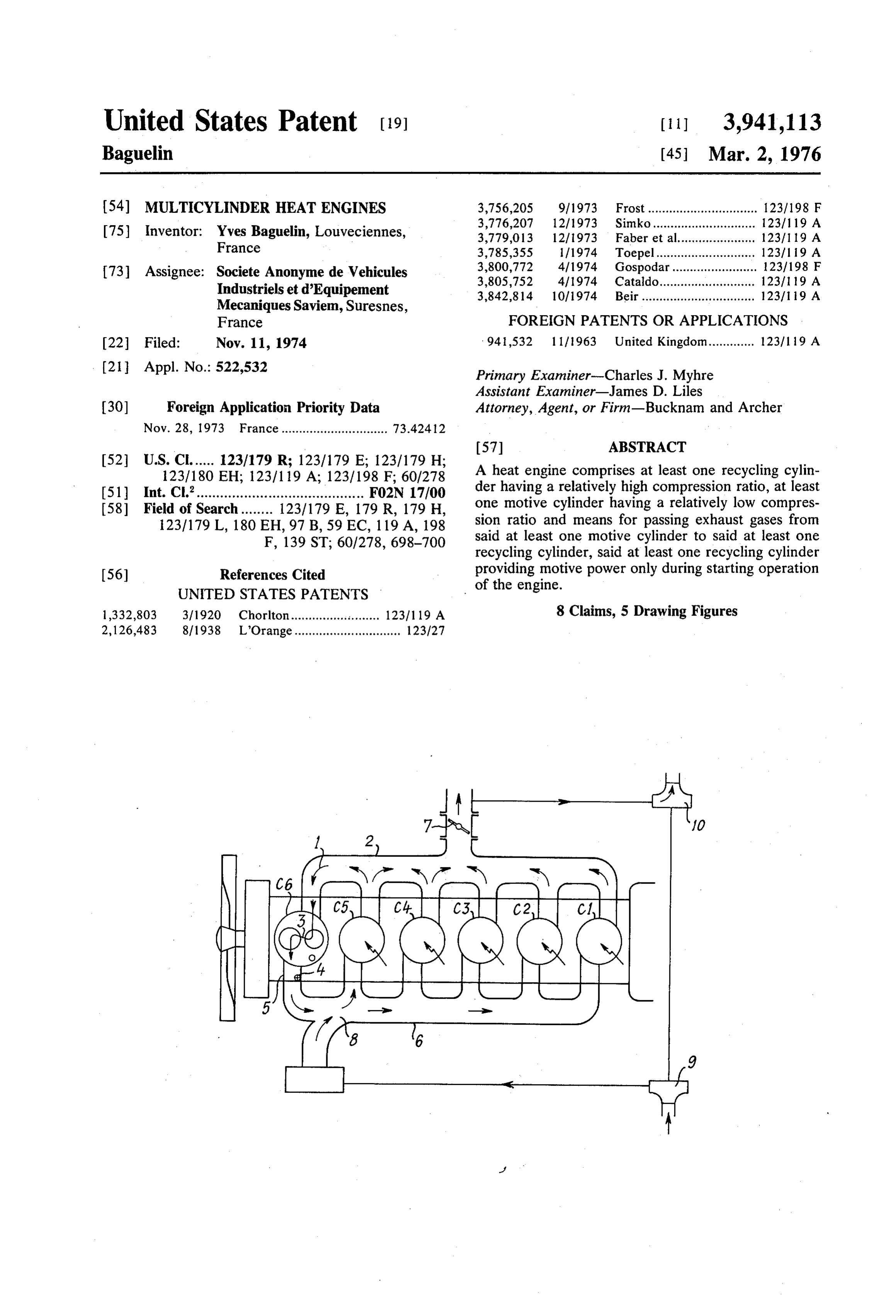
The present invention relates to multicylinder heat 5 ders C to Cs.
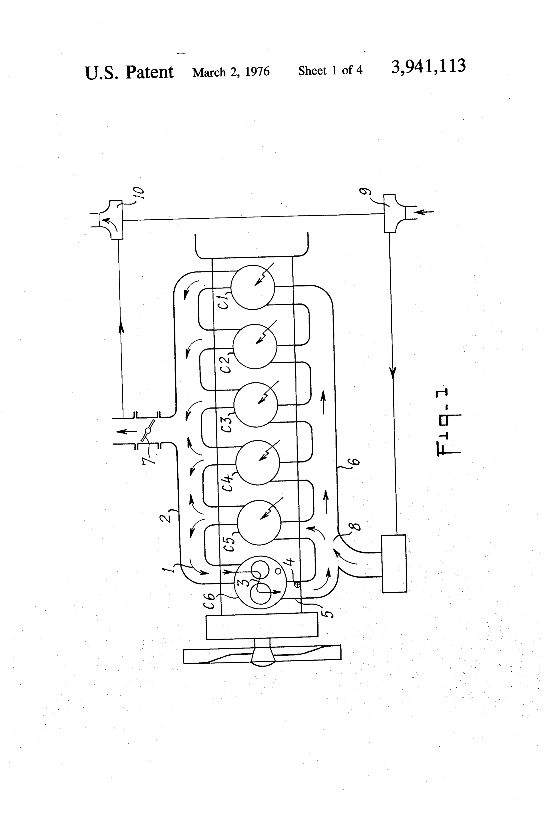
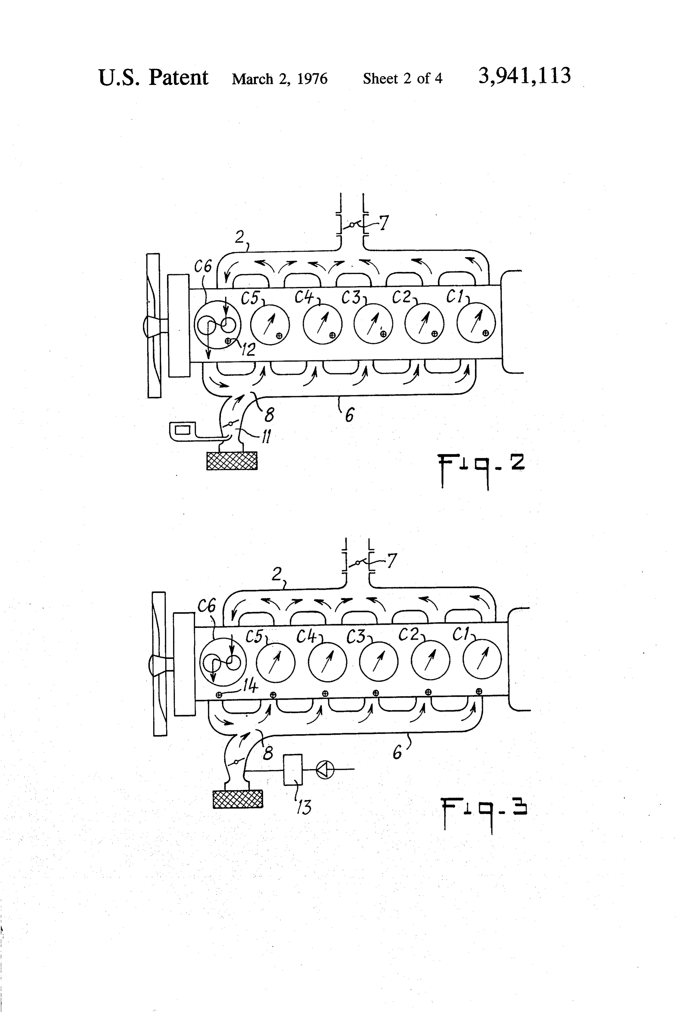
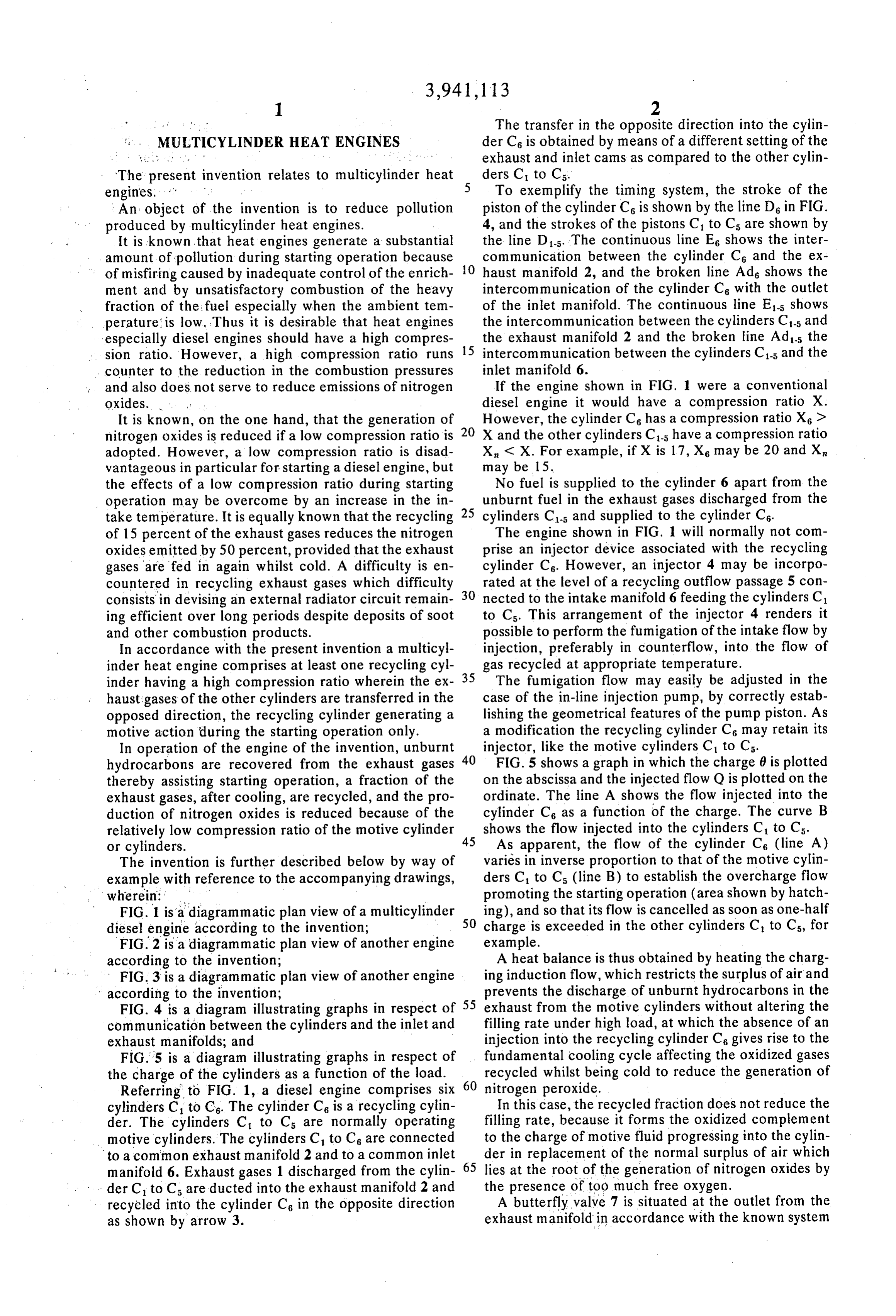
engines. To exemplify the timing system, the stroke of the An object of the invention is to reduce pollution piston of the cylinder C6 is shown by the line D in FIG. produced by multicylinder heat engines. 4, and the strokes of the pistons C to Cs are shown by It is known that heat engines generate a substantial the line D1-5. The continuous line Es shows the inter amount of pollution during starting operation because O communication between the cylinder C6 and the ex of misfiring caused by inadequate control of the enrich haust manifold 2, and the broken line Ad shows the ment and by unsatisfactory combustion of the heavy intercommunication of the cylinder Cs with the outlet fraction of the fuel especially when the ambient tem of the inlet manifold. The continuous line E-5 shows perature is low. Thus it is desirable that heat engines the intercommunication between the cylinders C-5 and especially diesel engines should have a high compres the exhaust manifold 2 and the broken line Ads the sion ratio. However, a high compression ratio runs 15 intercommunication between the cylinders C-5 and the counter to the reduction in the combustion pressures inlet manifold 6.
and also does not serve to reduce emissions of nitrogen If the engine shown in FIG. 1 were a conventional oxides. . . . diesel engine it would have a compression ratio X. It is known, on the one hand, that the generation of 20 However, the cylinder C6 has a compression ratio X > nitrogen oxides is reduced if a low compression ratio is X and the other cylinders C-5 have a compression ratio adopted. However, a low compression ratio is disad X, < X. For example, if X is 17, Xs may be 20 and X, vantageous in particular for starting a diesel engine, but may be 15.
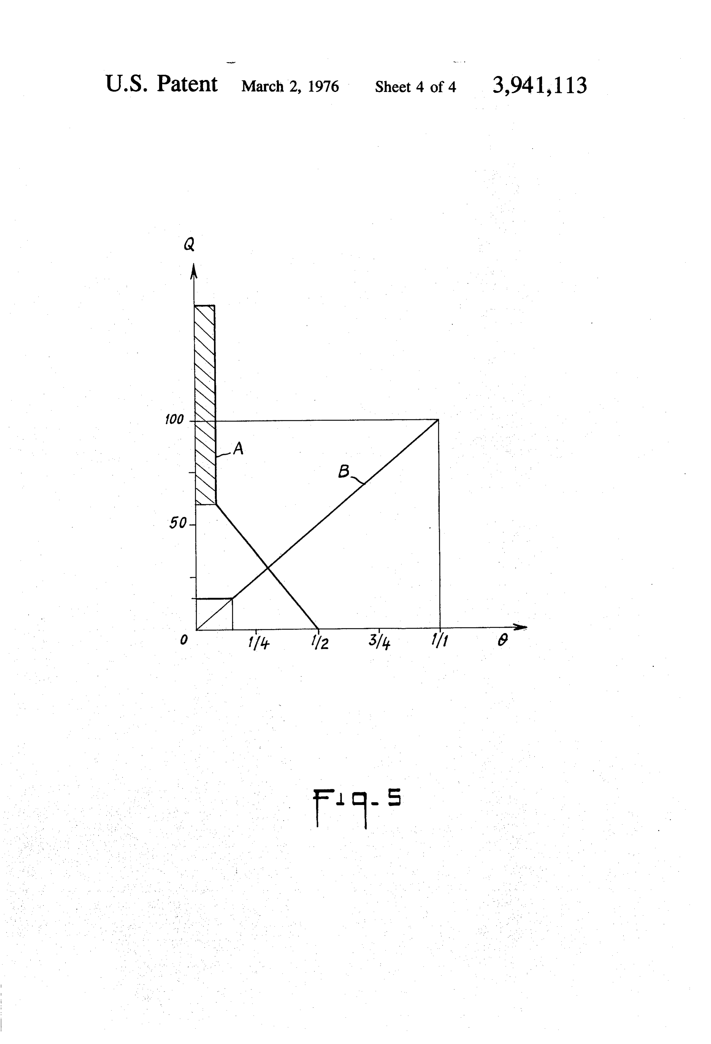
the effects of a low compression ratio during starting No fuel is supplied to the cylinder 6 apart from the operation may be overcome by an increase in the in 25 unburnt fuel in the exhaust gases discharged from the take temperature. It is equally known that the recycling cylinders C-5 and supplied to the cylinder Cs. of 15 percent of the exhaust gases reduces the nitrogen The engine shown in FIG. 1 will normally not com oxides emitted by 50 percent, provided that the exhaust prise an injector device associated with the recycling gases are fed in again whilst cold. A difficulty is en cylinder Cs. However, an injector 4 may be incorpo countered in recycling exhaust gases which difficulty 30 rated at the level of a recycling outflow passage 5 con consists in devising an external radiator circuit remain nected to the intake manifold 6 feeding the cylinders C1 ing efficient over long periods despite deposits of soot to Cs. This arrangement of the injector 4 renders it and other combustion products. possible to perform the fumigation of the intake flow by In accordance with the present invention a multicyl injection, preferably in counterflow, into the flow of inder heat engine comprises at least one recycling cyl 35 gas recycled at appropriate temperature. inder having a high compression ratio wherein the ex The fumigation flow may easily be adjusted in the haust gases of the other cylinders are transferred in the case of the in-line injection pump, by correctly estab opposed direction, the recycling cylinder generating a lishing the geometrical features of the pump piston. As motive action during the starting operation only. a modification the recycling cylinder C6 may retain its In operation of the engine of the invention, unburnt 40 injector, like the motive cylinders C to Cs. hydrocarbons are recovered from the exhaust gases FIG. 5 shows a graph in which the charge 0 is plotted thereby assisting starting operation, a fraction of the on the abscissa and the injected flow Q is plotted on the exhaust gases, after cooling, are recycled, and the pro ordinate. The line A shows the flow injected into the duction of nitrogen oxides is reduced because of the cylinder C6 as a function of the charge. The curve B relatively low compression ratio of the motive cylinder 45 shows the flow injected into the cylinders C to Cs. or cylinders. As apparent, the flow of the cylinder Cs (line A) The invention is further described below by way of varies in inverse proportion to that of the motive cylin example with reference to the accompanying drawings, ders C to Cs (line B) to establish the overcharge flow wherein: promoting the starting operation (area shown by hatch FIG. 1 is a diagrammatic plan view of a multicylinder 50 ing), and so that its flow is cancelled as soon as one-half diesel engine according to the invention; charge is exceeded in the other cylinders C to Cs, for FIG. 2 is a diagrammatic plan view of another engine example.
according to the invention; A heat balance is thus obtained by heating the charg FIG. 3 is a diagrammatic plan view of another engine ing induction flow, which restricts the surplus of air and according to the invention; prevents the discharge of unburnt hydrocarbons in the FIG. 4 is a diagram illustrating graphs in respect of 55 exhaust from the motive cylinders without altering the communication between the cylinders and the inlet and filling rate under high load, at which the absence of an exhaust manifolds; and injection into the recycling cylinder Cs gives rise to the FIG. 5 is a diagram illustrating graphs in respect of fundamental cooling cycle affecting the oxidized gases the charge of the cylinders as a function of the load. 60 recycled whilst being cold to reduce the generation of Referring to FIG. 1, a diesel engine comprises six nitrogen peroxide.
cylinders C to Cs. The cylinder C6 is a recycling cylin In this case, the recycled fraction does not reduce the der. The cylinders C to Cs are normally operating filling rate, because it forms the oxidized complement motive cylinders. The cylinders C to Cs are connected to the charge of motive fluid progressing into the cylin to a common exhaust manifold 2 and to a common inlet der in replacement of the normal surplus of air which manifold 6. Exhaust gases 1 discharged from the cylin 65 lies at the root of the generation of nitrogen oxides by der C to C are ducted into the exhaust manifold 2 and the presence of too much free oxygen. recycled into the cylinder Cs in the opposite direction A butterfly valve 7 is situated at the outlet from the as shown by arrow 3. exhaust manifold in accordance with the known system
Page 7
for increasing the engine-braking action. In the case of the diesel engine, it is apparent that the Upstream of the points of supply to the normally low compression ratio of the motive cylinders which is operating cylinders C to Cs, the inlet manifold 6 has a rendered possible allows of an improvement in durabil node 8 at which the mixing of fresh and of the recycled ity and in a reduction in the generation of nitrogen exhaust gas is performed, with or without fumigation. oxides. Moreover, the starting operation is assisted and The engine may be supercharged by means of a com the wastage of hydrocarbons is reduced. The cooled pressor 9 driven by a turbine 10 which is itself driven by gases discharged from the cylinder Cs, irrespective of means of the exhaust gases. The recycling system does the purity of the exhaust, serve as an automatically not affect the external supercharging circuit, since it is 10 metered charge of inert gas which restricts the genera internal to the engine. tion of nitrogen oxides without altering the filling rate In the case of the supercharged diesel engine, the of the motive cylinders C-5.
elimination of one motive cylinder which provides a The elimination of one motive cylinder in the case of recycling cylinder Cs, may be made up in respect of the the six cylinder engine may be made up by a high de rated performance figures of the engine by a higher gree of supercharging, more easily acceptable by mo degree of supercharge rendered acceptable by the 15 tive cylinders having a low compression ratio. lower volumetric compression ratio of the power cylin The recycling cylinder Cs cannot be taken into ac ders C to Cs, the ease of starting being safeguarded by count in the calculation of the swept volume of the the initial action of the recycling cylinder having a high engine. The cylinder Cs may even be deducted by vir compression ratio. tue of its reversed flow.
The exhaust throttle 7 is closed when starting, so that 20 It should be noted that the mass fraction of recycled the cylinder Cs receives the exhaust from the cylinders gas is approximately equal to:
C-5. The initial misfires exhausted from the cylinders
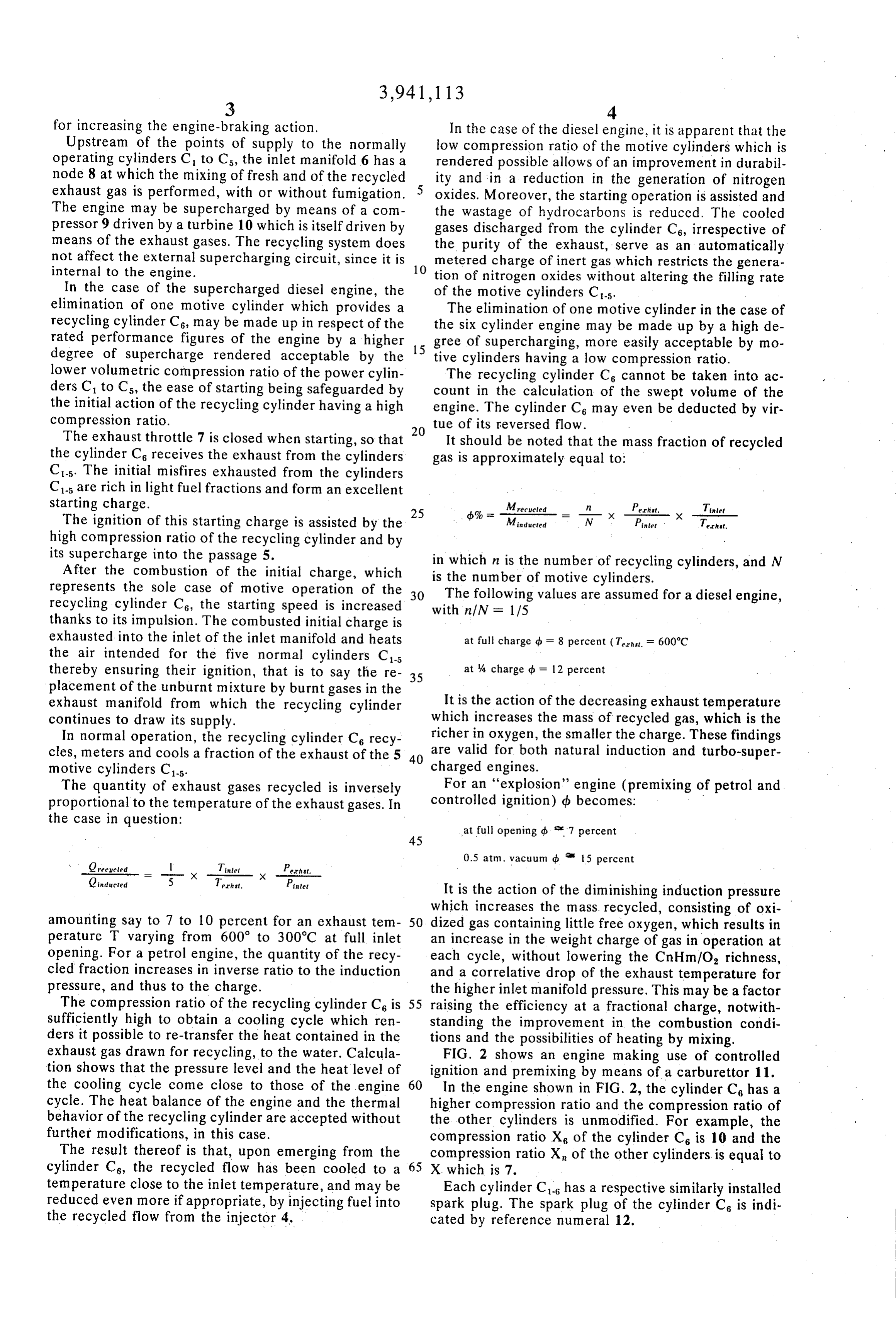
C-5 are rich in light fuel fractions and form an excellent starting charge. Mrerueled Perht, Tinlet The ignition of this starting charge is assisted by the 25 Minducted = W Pintet Ternst. high compression ratio of the recycling cylinder and by its supercharge into the passage 5. in which n is the number of recycling cylinders, and N After the combustion of the initial charge, which is the number of motive cylinders.
represents the sole case of motive operation of the The following values are assumed for a diesel engine, recycling cylinder Cs, the starting speed is increased 30 with n/N = 1/5 thanks to its impulsion. The combusted initial charge is exhausted into the inlet of the inlet manifold and heats at full charge d = 8 percent (T. = 600°C the air intended for the five normal cylinders C-5 thereby ensuring their ignition, that is to say the re 35 at % charge d = 12 percent placement of the unburnt mixture by burnt gases in the exhaust manifold from which the recycling cylinder It is the action of the decreasing exhaust temperature continues to draw its supply. which increases the mass of recycled gas, which is the In normal operation, the recycling cylinder Cs recy richer in oxygen, the smaller the charge. These findings cles, meters and cools a fraction of the exhaust of the 5 40 are valid for both natural induction and turbo-super motive cylinders Cs. charged engines.
The quantity of exhaust gases recycled is inversely For an “explosion' engine (premixing of petrol and proportional to the temperature of the exhaust gases. In controlled ignition) db becomes: the case in question: at full opening db 7 percent
Tinlet 0.5 atm. vacuum db 15 percent
Qinducted 5 Terhit. Pintet
It is the action of the diminishing induction pressure which increases the mass recycled, consisting of oxi amounting say to 7 to 10 percent for an exhaust tem 50 dized gas containing little free oxygen, which results in perature T varying from 600 to 300°C at full inlet an increase in the weight charge of gas in operation at opening. For a petrol engine, the quantity of the recy each cycle, without lowering the CnHm/O, richness, cled fraction increases in inverse ratio to the induction and a correlative drop of the exhaust temperature for pressure, and thus to the charge. the higher inlet manifold pressure. This may be a factor The compression ratio of the recycling cylinder C6 is 55 raising the efficiency at a fractional charge, notwith sufficiently high to obtain a cooling cycle which ren standing the improvement in the combustion condi ders it possible to re-transfer the heat contained in the tions and the possibilities of heating by mixing. exhaust gas drawn for recycling, to the water. Calcula FIG. 2 shows an engine making use of controlled tion shows that the pressure level and the heat level of ignition and premixing by means of a carburettor 11. the cooling cycle come close to those of the engine 60 In the engine shown in FIG. 2, the cylinder C6 has a cycle. The heat balance of the engine and the thermal higher compression ratio and the compression ratio of behavior of the recycling cylinder are accepted without the other cylinders is unmodified. For example, the further modifications, in this case. compression ratio X of the cylinder C6 is 10 and the The result thereof is that, upon emerging from the compression ratio X of the other cylinders is equal to cylinder Cs, the recycled flow has been cooled to a 65 X which is 7.
temperature close to the inlet temperature, and may be Each cylinder C has a respective similarly installed reduced even more if appropriate, by injecting fuel into spark plug. The spark plug of the cylinder C6 is indi the recycled flow from the injector 4. cated by reference numeral 12.
Page 8
FIG. 3 shows an engine making use of indirect petrol 3. An engine according to claim 1, wherein the num injection. The engine comprises an injection assembly ber of motive cylinders is equal to 4 or 5 times the 13 like that of a similar, but conventional engine with number of recycling cylinders.
out a recycling cylinder and wherein may be retained 4. An engine according to claim 1, wherein an ex the branch associated with the recycling cylinder Cs. haust manifold is connected to said motive cylinder, a An injector 14 is associated with the recycling cylin region of the exhaust manifold, which in operation of der Cs. The injector 14 injects in counterflow at the the engine is the coolest region of the exhaust manifold, side of the inlet duct into the emergent flow, which is connected to said recycling cylinder, and the exhaust contributes to the infeed of atomized fuel the emergent 10 manifold is provided with a shut-off member for caus flow bears and if possible preheats before it is mixed to ing exhaust gas from said motive cylinder to be passed with the inducted air flow whereof the temperature is thesaid recycling cylinder during starting operation of raised by being mixed with the recycled oxidized gases. brake duringthenormal engine, shut-off member acting as an exhaust operation of the engine.
The compression ratio of the recycling cylinder C 5. A heat engine according to claim 1, comprising may be selected in such manner that the outflow tem 15 means for passing exhaust gas from said recycling cylin perature of the recycled gas undergoing the cooling der to said motive cylinder. cycle is such that a reheating action of adequate magni 6. A heat engine according to claim 5, wherein said tude is obtained in the inlet manifold 6.
I claim: exhaust gas passing means comprises an exhaust duct 1. A heat engine comprising at least one recycling connected is connected to said recycling cylinder, an inlet manifold to said motive cylinder and the exhaust cylinder having a given compression ratio, at least one motive cylinder having a compression ratio less than duct opens into the exhaust manifold at its upstream end in such manner as to promote mixing of gas recy that of said recycling cylinder and means for passing cled from said recycling cylinder with fresh gas sup exhaust gases from said motive cylinder to said recy plied to said inlet manifold.
cling cylinder, said recycling cylinder being operable to 25 7. An engine according to claim 1, wherein a fumiga provide motive power only during starting operation of tion injector is situated in a recycling duct at the outlet the engine. of said recycling cylinder.
2. A heat engine according to claim 1, wherein the 8. An engine according to claim 7, wherein said fumi engine is a diesel engine and the compression ratio of gation injector has a jet directed towards the recycling said motive cylinder is optimum for operation when the 30 cylinder.
engine is hot. sk sk : ck
Provenance
- Collection
- Cited prior art
- Original PDF
- patentimages.storage.googleapis.com →
- Filed
- 1974-11-11
- Pages
- 8
- Method
- pdftotext (the PDF's own text layer) + pdftoppm 300dpi page scans
- Source
- Google Patents bibliographic record
- Granted
- 1976-03-02
- Inventors
- Yves Baguelin; VEHICULES INDUSTRIELS ET D EQUIPEMENT MECHANIQUE SA
- Transcribed from
- patentimages.storage.googleapis.com →