patent · US4159700
Internal combustion compound engines
3 July 1979
Page 1 — bibliographic record
United States Patent (19) 11) 4,159,700 McCrum 45 Jul. 3, 1979
54 NTERNAL COMBUST ON COMPOUND
FOREIGN PATENT DOCUMENTS
ENGINES
0466528 11/1951 Italy ........................................... 60/622 (76) Inventor: William H. McCrum, Candlewood
Mountain Rd., New Milford, Conn. Primary Examiner-Charles J. Myhre 06776 Assistant Examiner-C. R. Feinberg
Attorney, Agent, or Firm-E. Seward Stevens (21) Appl. No.: 901,646 57 ABSTRACT (22) Filed: May 1, 1978 This invention relates to improving the internal com bustion and internal use of fuel in reciprocating engines,
Related U.S. Application Data and more particularly to reciprocating engines which 63 Continuation-in-part of Ser. No. 734,638, Oct. 18, 1976, are compounded in order to effect extension of the Pat. No. 4,086,882. expansion event of the four-event work cycle of such engines and which are enabled especially thereby to (51) Int. C.’.............................................. FO2B 75/20 receive and use, for prolonging and substantially im (52) U.S. C. ........................... ...... 123/59 EC; 60/619; proving the combustion process, secondary air inducted 60/620; 123/1 R and compressed by secondary cylinders of such en (58) Field of Search ................ 123/59 EC, 53 A, 1 R, gines, said air being subsequently applied directly to and 123/37, 59 BM, 64; 60/622,619, 620, 623 into the engine's working medium after the original (56) References Cited ignition of each fuel/air charge or any equivalent thereof, and during the power-producing period in
2,196,228 4/1940 Prescott ............................. 123/53. A cylinders.
3,789,807 2/1974 Pinkerton .. 123/59 EC 4,075,980 2/1978 Anger ............................. 123/59 EC 3 Claims, 8 Drawing Figures
SECONDARY
NTAKE-ul TERMINA
Í 38
Page 2
Drawing sheet — no readable text.
Page 3
Drawing sheet — no readable text.
Page 4
Drawing sheet — no readable text.
Page 5
Drawing sheet — no readable text.
Page 6
The engines of the other three inventions are of the
INTERNAL COMBUST ON COMPOUND two-stage-combustion type, rather than the compound
In such engine, the working medium ceases working
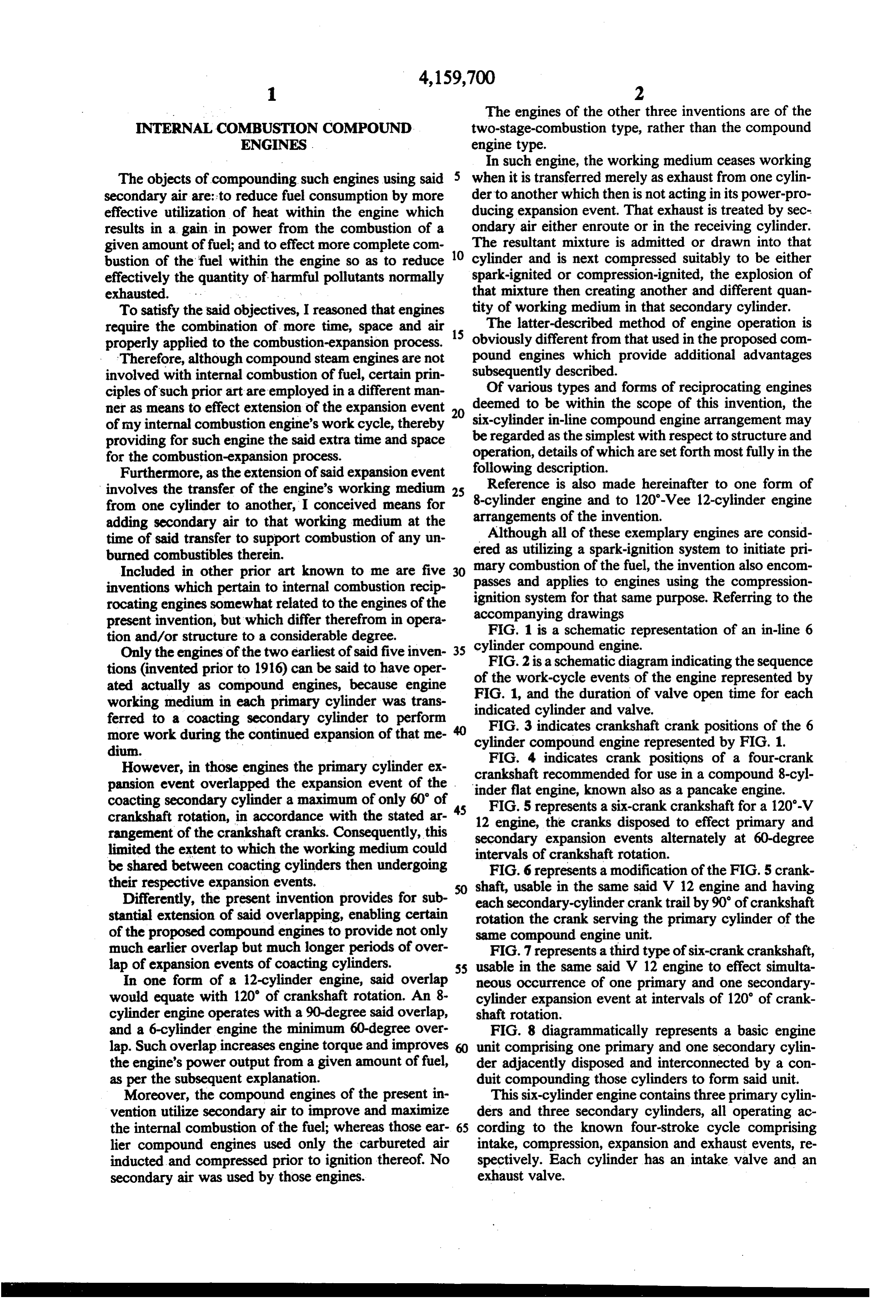
The objects of compounding such engines using said when it is transferred merely as exhaust from one cylin secondary air are: to reduce fuel consumption by more der to another which then is not acting in its power-pro effective utilization of heat within the engine which ducing expansion event. That exhaust is treated by sec results in a gain in power from the combustion of a ondary air either enroute or in the receiving cylinder. given amount of fuel; and to effect more complete com 10 The resultant mixture is admitted or drawn into that bustion of the fuel within the engine so as to reduce cylinder and is next compressed suitably to be either effectively the quantity of harmful pollutants normally spark-ignited or compression-ignited, the explosion of exhausted. that mixture then creating another and different quan To satisfy the said objectives, I reasoned that engines tity of working medium in that secondary cylinder. require the combination of more time, space and air 15 The latter-described method of engine operation is properly applied to the combustion-expansion process. obviously different from that used in the proposed com Therefore, although compound steam engines are not pound engines which provide additional advantages involved with internal combustion of fuel, certain prin subsequently described.
ciples of such prior art are employed in a different man Of various types and forms of reciprocating engines deemed to be within the scope of this invention, the ner as means to effect extension of the expansion event 20 six-cylinder of my internal combustion engine's work cycle, thereby be regarded as in-line compound engine arrangement may providing for such engine the said extra time and space the simplest with respect to structure and for the combustion-expansion process. operation, details of which are set forth most fully in the Furthermore, as the extension of said expansion event following description.
involves the transfer of the engine's working medium 25 Reference is also made hereinafter to one form of 8-cylinder engine and to 120'-Vee 12-cylinder engine from one cylinder to another, I conceived means for arrangements adding secondary air to that working medium at the of the invention. time of said transfer to support combustion of any un ered Although all of these exemplary engines are consid burned combustibles therein. as utilizing a spark-ignition system to initiate pri mary combustion of the fuel, the invention also encom
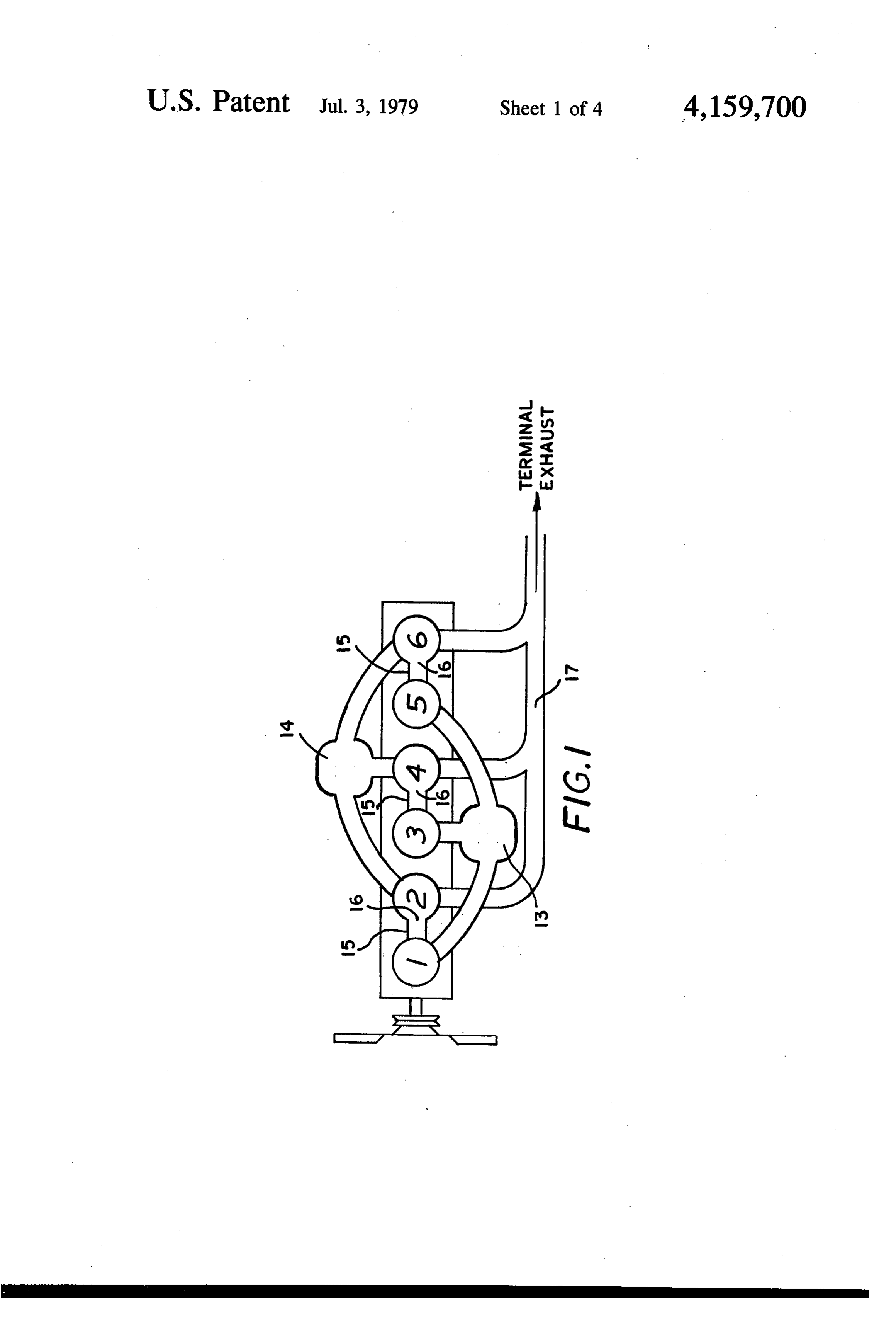
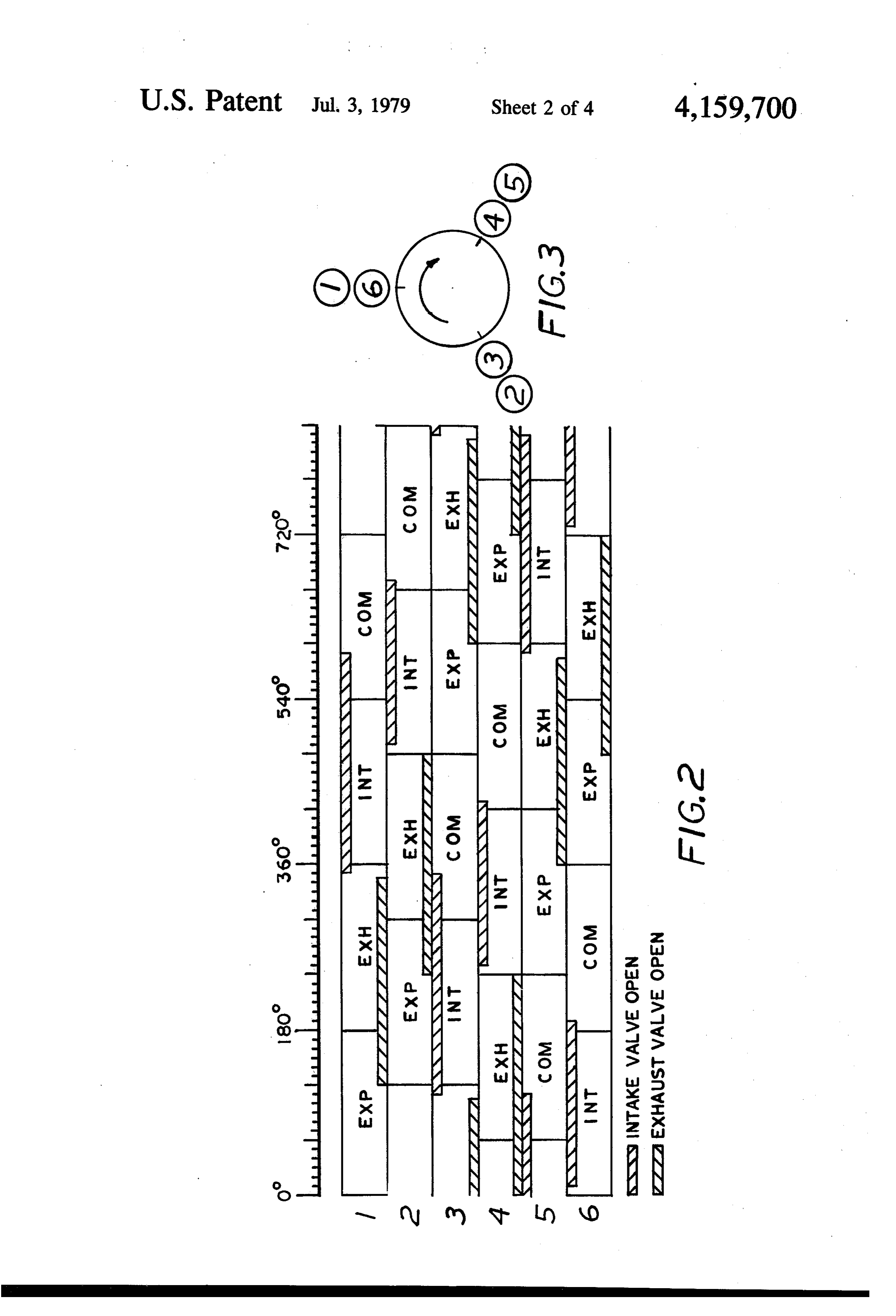
Included in other prior art known to me are five 30 passes inventions which pertain to internal combustion recip ignitionand applies to engines using the compression system for that same purpose. Referring to the rocating engines somewhat related to the engines of the accompanying drawings present invention, but which differ therefrom in opera FIG. 1 is a schematic representation of an in-line 6 tion and/or structure to a considerable degree. cylinder compound engine.
Only the engines of the two earliest of said five inven FIG. 2 is a schematic diagram indicating the sequence tions (invented prior to 1916) can be said to have oper of the work-cycle events of the engine represented by ated actually as compound engines, because engine FIG. 1, and the duration of valve open time for each working medium in each primary cylinder was trans indicated cylinder and valve. ferred to a coacting secondary cylinder to perform FIG. 3 indicates crankshaft crank positions of the 6 more work during the continued expansion of that me cylinder compound engine represented by FIG. 1. dium.
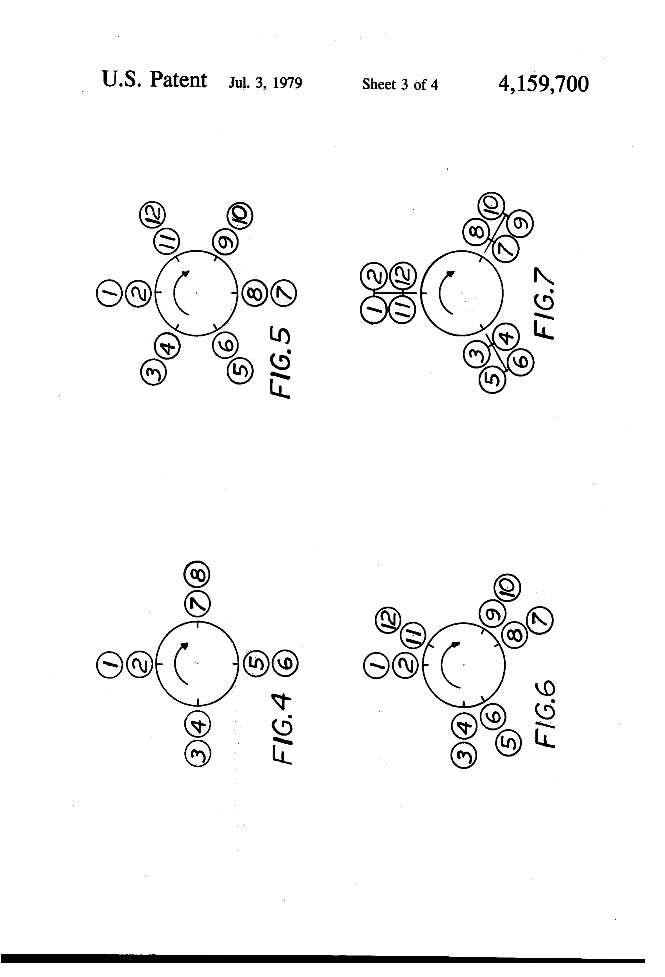
However, in those engines the primary cylinder ex FIG. 4 indicates crank positions of a four-crank pansion event overlapped the expansion event of the . crankshaft recommended for use in a compound 8-cyl coacting secondary cylinder a maximum of only 60' of inder flat engine, known also as a pancake engine. FIG. 5 represents a six-crank crankshaft for a 120-V crankshaft rotation, in accordance with the stated ar 12 engine, the cranks disposed to effect primary and rangement of the crankshaft cranks. Consequently, this secondary expansion events alternately at 60-degree limited the extent to which the working medium could be shared between coacting cylinders then undergoing intervalsFIG. 6 of crankshaft rotation.
represents a modification of the FIG. 5 crank their respective expansion events. shaft, usable in the same said V12 engine and having Differently, the present invention provides for sub each secondary-cylinder crank trail by 90' of crankshaft stantial extension of said overlapping, enabling certain rotation the crank serving the primary cylinder of the of the proposed compound engines to provide not only same compound engine unit.
much earlier overlap but much longer periods of over FIG. 7 represents a third type of six-crank crankshaft, lap of expansion events of coacting cylinders. 55 usable in the same said V12 engine to effect simulta In one form of a 12-cylinder engine, said overlap neous occurrence of one primary and one secondary would equate with 120' of crankshaft rotation. An 8 cylinder expansion event at intervals of 120' of crank cylinder engine operates with a 90-degree said overlap, shaft rotation.
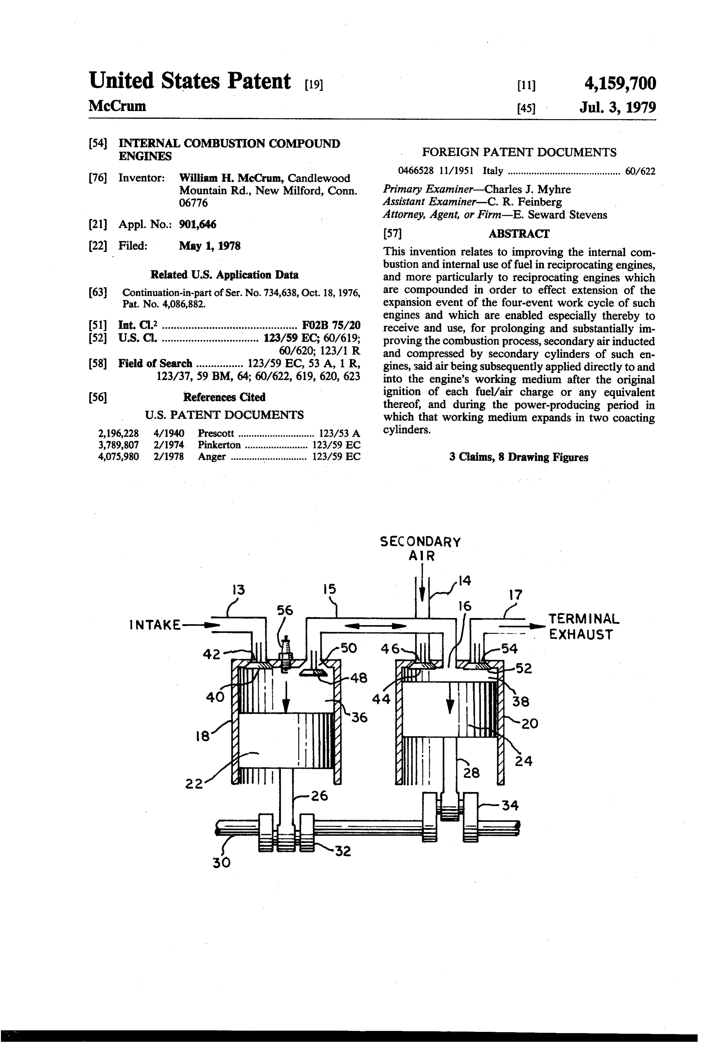
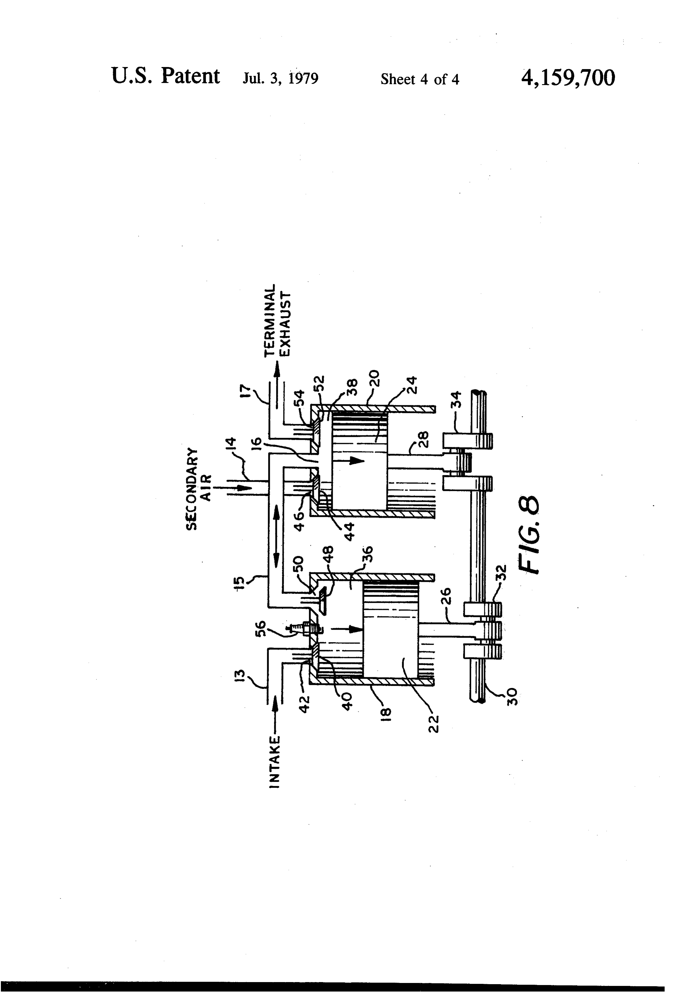
and a 6-cylinder engine the minimum 60-degree over FIG. 8 diagrammatically represents a basic engine lap. Such overlap increases engine torque and improves unit comprising one primary and one secondary cylin the engine's power output from a given amount of fuel, der adjacently disposed and interconnected by a con as per the subsequent explanation. duit compounding those cylinders to form said unit. Moreover, the compound engines of the present in This six-cylinder engine contains three primary cylin vention utilize secondary air to improve and maximize ders and three secondary cylinders, all operating ac the internal combustion of the fuel; whereas those ear 65 cording to the known four-stroke cycle comprising lier compound engines used only the carbureted air intake, compression, expansion and exhaust events, re inducted and compressed prior to ignition thereof. No spectively. Each cylinder has an intake valve and an secondary air was used by those engines. exhaust valve.
Page 7
Only the primary cylinders are provided with a spark The power-producing expansion event follows as ignition system. Those cylinders are numbered 1, 3, 5 on piston 22 undergoes a downstroke, also known as the FIG. 1 and operate in conventional manner. piston's power stroke.
During each intake event, a primary air/fuel charge is It is such a power stroke that is picturized in FIG. 8 inducted by the respective primary cylinder through 5 wherein the working medium, created by the explosion the conventional intake manifold and fuel/air system 13, of said mixture in combustion chamber 36, is expanding which includes a carburetor and air cleaner (not against piston 22 causing same to rotate crankshaft 30 shown). via the force applied to crank 32 through the connect Three conduits of said system 13 are shown connect ing rod 26.
ing the primary cylinders, the point of connection being O It is shown in FIG. 8 that crank 32 is at 60' BBC, the intake port of respective cylinders. having moved 120 from its top dead center (TDC) The intake port of each of the secondary cylinders position in terms of crankshaft rotation. The engine of (2,4,6) is similarly connected to a separate manifold 14 this particular example calls for exhaust valve 48 to be serving as a secondary-air supply system, including an opened 60 BBC as shown.
air filter (not shown). During the intake event of each secondary cylinder, atmospheric air is drawn through four-event cycle 120' later cylinder Meanwhile, secondary 20 commenced its than the start of said primary said system 14 and inducted by that cylinder. cycle. During the intake event in cylinder 20, secondary Three short conduits 15 are shown on FIG. 1, each air was drawn through said manifold 14 and intake port conduit separately connecting, and thereby compound 46 past the then-open intake valve 44 and into the com ing to form an engine unit, one primary and one adja 20 cent secondary cylinder. Preferably, these conduits 15 bustion piston chamber 38 by the down-stroke movement of
are in-cylinder-head conduits, cast as integral parts of Both exhaust valves 48 and 52 were in closed position the cylinder head. Each of these conduits connects the during exhaust port of the respective primary cylinder to the event inboth that intake event and the next compression cylinder 20. Thus, the pressurized secondary combustion chamber of said adjacent secondary cylin 25 air der, whereat the conduit 15 ends as a valveless, (con saidinconstantly-open chamber 38 extended also into said conduit 15 via port 16, up to the then-closed ex stantly-open) port 16.
Such constant opening is schematically picturized on haust valve 48. The higher-pressured gases then in FIG. 1 as the open section or missing part of the "cir chamber 36 prevented valve 48 from becoming un cle' drawn around the cylinder numbers 2, 4, 6. (Where 30 seated by the pressured air in conduit 15. the circle is seen drawn between any cylinder number As shown in FIG. 8, piston 24, crank 34 and connect and any conduit leading to and connecting that cylin ing rod 28 are at TDC position, ready to start the expan der, the presence of a valve is indicated-intake valve sion event in cylinder 20. Exhaust valve 52 is closed. governing the intake manifold, and exhaust valve gov As said exhaust valve 48 opens in the primary cylin erning the exhaust manifold). 35 der 18, the power-producing working medium at high When the exhaust valve of any secondary cylinder temperature and pressure attempts to charge into and opens, the gases in that cylinder are released to the through the pressured secondary air in conduit 15. connected exhaust manifold 17 as final exhaust from the Combustion results as unburned burnables in said me engine. That exhaust passes through a conventional dium contact said secondary air, itself serving then as exhaust system (not shown) to the atmosphere. 40 part of the working medium. Practically simulta It is observed on FIG. 1 that this 6-cylinder engine neously, pressures equalize in chambers 36, 38 and in comprises three compound engine units consisting of conduit 15, the expansive force of said medium then paired cylinders. Cylinders 1 and 2 represent one engine being applied against both pistons 22 and 24 which unit; cylinders 3 and 4 form a second unit; and cylinders participate further in rotating crankshaft 30. 5 and 6 the third unit. To effect the subsequently 45 A novel feature of this invention is illustrated by the described coaction between the two cylinders of each double-headed arrow shown in conduit 15 of FIG. 8 to said unit, the primary-cylinder exhaust valves in this indicate flow of said fluids in either direction whenever engine are timed to open 60' BBC. the primary exhaust valve (such as valve 48) is open. As FIG. 8 schematically typifies one of such compound will be explained subsequently, the direction of said engine units as would apply to certain spark-ignition SO flow depends upon the direction of piston travel and the engines of this invention. speed of either piston over that of the other at any given Cylinder 18 is the primary cylinder of that engine moment. Advantages resulting therefrom will also be unit, operating as a four-stroke prime mover in conven explained later, along with other advantages offered by tional manner and according to the said cycle of four this invention.
eVents. 55 Exhaust-to-atmosphere is delayed some 120' of During the intake event, piston 22 commences its crankshaft rotation per this unit in FIG. 8, thus allowing downstroke, exhaust valve 48 being closed and intake that air-treated working medium a greatly-increased valve 40 open. Primary air/fuel mixture is drawn amount of time to perform its useful work. When crank through said manifold 13 until the intake port 42 is 34 reaches 60 BBC, exhaust valve 52 will open to allow timely closed by valve 40. fluids from chambers 36 and 38 to flow through exhaust The mixture is next compressed during the subse port 54 and the said exhaust manifold 17. quent upstroke of piston 22. At or near the end of that One advantage among other advantages of this inven compression event, said mixture is ignited by a spark tion would make it possible for a manufacturer of 6-cyl from spark plug 56 and a conventional ignition system inder in-line engines to convert and transform those normally connected thereto. (In other engines accord engines into compound engines according to FIG. 1 ing to this invention, fuel would be injected rather than while still retaining much of their original structure. inducted; and in still other engines compression ignition Hence, manufacturing costs should not be unduly in would replace the spark ignition system). creased as a result of the changeover.
Page 8
The operation of such a 6-cylinder in-line compound Therefore, the combined leverages considerably in engine is described first, together with certain of the crease the engine's torque output while only one charge structural details. Other details will be added concern is exploded.
ing the conversion of the conventional to the compound During the period between 120 and 150 per said engine and the differences between same. scale, the speed of piston 1 is greater than that of piston This compound engine's operation is perceived easily 2. This produces the effect of drawing more secondary by referring to FIG. 2 while reading the following air from cylinder 2 into cylinder 1, combustion therein explanation. improving accordingly.
At the top of FIG. 2, a scale is shown to indicate Piston speed becomes equal in both cylinders at 150 rotation of the crankshaft in intervals of 10 degrees, O per scale, when the crank for cylinder 1 reaches 30 drawn to reasonable accuracy for checking description BBC with crank for cylinder 2 then at 30 ATC. content therewith where desired. Numbers 1 to 6 at the Throughout the next 90 of crankshaft rotation (150° to left of FIG. 2 represent the respective cylinders, the 240 on scale), piston speed is faster in cylinder 2 and four events of each being shown to the right of said the crank serving same provides comparatively greater numbers. 5 leverage. This enables the working medium to enter Legends are shown on FIG. 2 to indicate the respec cylinder 2 more rapidly and become exposed more to tive intake and exhaust valves of the engine, and serve residual secondary air to again further the combustion to picturize the described timing of the valves with process and power output.
respect to their opening, closing and open-time dura An uncommon effect occurs during the said 90 per tion. 20 iod. Even though piston 1 moves into its upward stroke As the engine operates, the expansion event in cylin at the 180 mark to transfer the exhaust of cylinder 1 der 1 is seen starting at 0 on said scale, and effected by through the exhaust port thereof to cylinder 2, the faster the ignition of the compressed fuel-air charge in that speed of piston 2 offsets the effects of the opposing cylinder. directions of the two pistons, whereby cylinder 2 is At 120 of crank travel per the scale, exhaust valve of 25 favored in its expansion event. cylinder 1 opens to share then the expansion event and At the scale's 240 mark, the following important the working medium with cylinder 2, said medium pass occurrences take place: the expansion event starts simi ing through said conduit to cylinder 2 which is then larly in primary cylinder 5 to effect the work output of commencing its expansion event, thus directly making the compounded cylinders 5 and 6; the exhaust port of said event common to both cylinders which then coact. 30 cylinder 2 opens (60 BBC as in all secondary cylinders Simultaneously, cylinder 2 coacts by sharing its in this engine); and the speed of pistons 1 and 2 is the previously-inducted, compressed, and heated secondary S8, air with cylinder 1 via the conduit. The very hot work Between 240 and 330 on the scale, the speed of ing medium then coming into contact with the hot sec piston 1 is greater than that of piston 2. Thus, piston 1 ondary air enables leftover combustibles in said medium 35 rapidly ejects the cylinder 1 exhaust gases into the ex to be burned, said air supporting the burning thereof. haust system by way of cylinder 2 and the exhaust port According to this invention, each primary cylinder thereof. Although in decreasing amount, piston 2 still exhaust valve governs the period during which actual produces positive and useful work until reaching the coaction occurs between compounded cylinders form 300 mark. Thereafer, piston 2 has an upstroke to ex ing a particular engine unit, the duration of that valve's haust cylinder 2, such event ending at the 480 scale open time being the measure of said period. mark whereat the cylinder 2 exhaust valve closes with At this point it is worthwhile to read the explanation piston 2 at TDC as cylinder 3 fires its charge. slowly and visualize, in slow-motion manner, other It is deemed inadvisable to provide “valve overlap' uncommon effects presumed to occur within this un in any cylinder for two reasons. First, the pressure of usual engine. 45 exhaust gases in compounded cylinders will be some When cylinder 1 exhaust valve opens, a portion of the what higher than that of conventional engines at the hot higher-pressured working medium in cylinder 1 end of the primary cylinder's exhaust event. Overlap spurts into cylinder 2 and into the lower-pressured sec would allow said higher pressure to prevent proper ondary air therein, so that gas pressures in both said induction of the next primary charge, particularly at cylinders may be made equal. 50 slow engine speeds. Hence it is recommended that pri Instantly and practically simultaneously the follow mary exhaust valves close at 15 BTC at which point ing occurrences take place: the spurt creates great tur coaction between compounded cylinders ceases. bulence in cylinder 2; unburned combustibles in said Each primary intake valve opens at 10 BTC and portion of working medium contact the secondary air, closes at 50 ABC, such timing being regarded as con whereby combustion is effected in cylinder 2; this com 55 ventional and suitable especially for cruising and higher bustion creates a momentary increase of gas pressure in engine speeds. At slow speeds under heavy load condi cylinder 2 above that in cylinder 1; that pressure in tions, the late closing at said 50' is said to tend to reduce crease and said turbulence tend to force some of the the amount of fuel-air charge inducted, thereby lessen secondary air out of cylinder 2 and into cylinder 1 to ing the possibility of detonation occurring in primary equalize the gas pressure; this extends the combustion cylinders under said conditions.
process in cylinder 1 wherein combustion of unburned The second reason for eliminating valve overlap con combustibles is supported by said secondary air. cerns secondary cylinders wherein little or nothing Pressures in both cylinders are rapidly equalized as could be gained from said overlap. Sufficient and ample they act on the doubled piston-head area. Additionally, secondary air will be inducted by secondary cylinders and importantly, crank leverage is simultaneously im 65 at any engine speeds whatever, by having secondary proved; because while one of the combined cranks is intake valves open at 10 ATC and close 10 ABC. losing its effective leverage angle during the power Such early closing time is particularly recommended stroke, the other crank's leverage angle is improving. to prevent said air from being expelled from secondary
Page 9
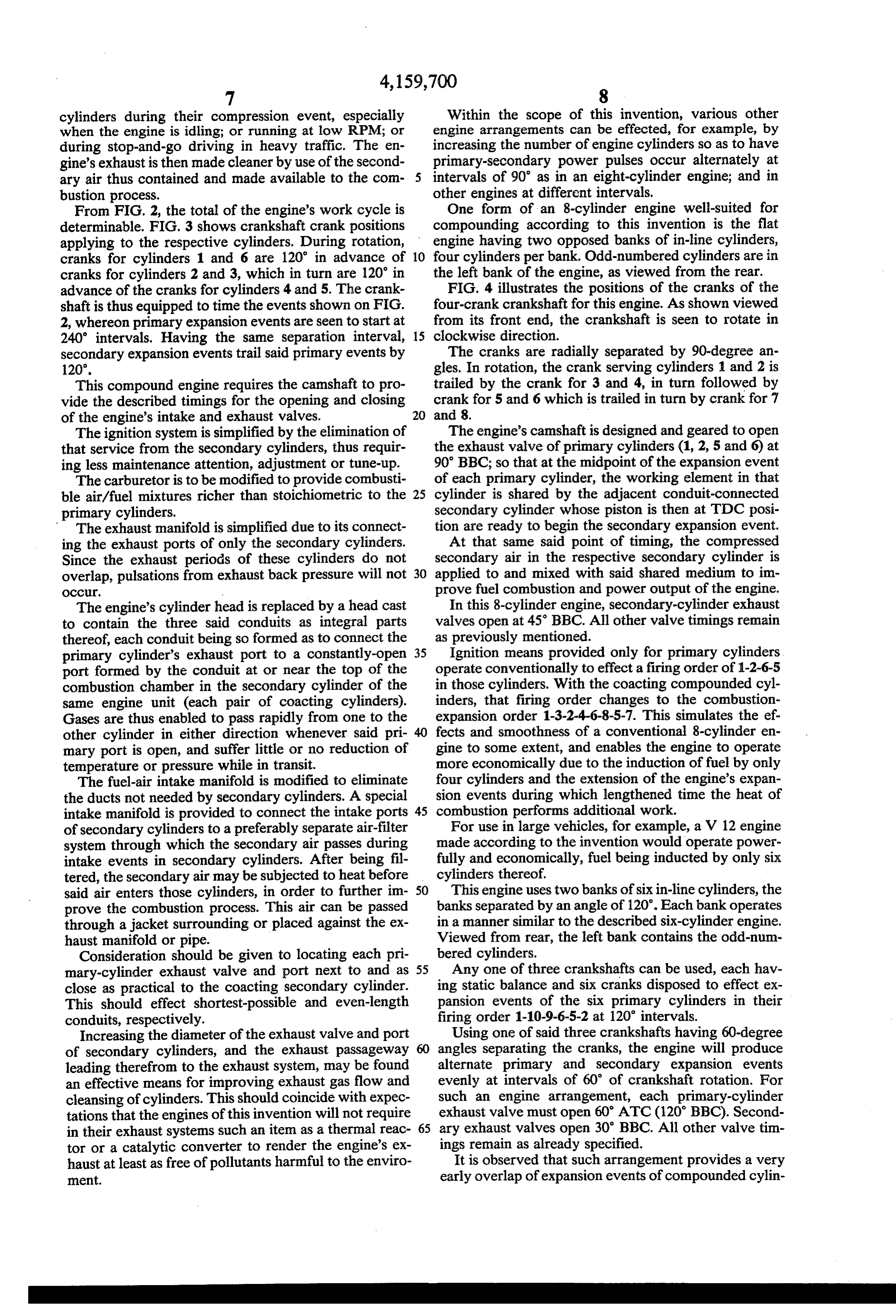
cylinders during their compression event, especially Within the scope of this invention, various other when the engine is idling; or running at low RPM; or engine arrangements can be effected, for example, by during stop-and-go driving in heavy traffic. The en increasing the number of engine cylinders so as to have gine's exhaust is then made cleaner by use of the second primary-secondary power pulses occur alternately at ary air thus contained and made available to the com intervals of 90 as in an eight-cylinder engine; and in bustion process. other engines at different intervals. From FIG. 2, the total of the engine's work cycle is One form of an 8-cylinder engine well-suited for determinable. FIG. 3 shows crankshaft crank positions compounding according to this invention is the flat applying to the respective cylinders. During rotation, engine having two opposed banks of in-line cylinders, cranks for cylinders 1 and 6 are 120 in advance of 10 four cylinders per bank. Odd-numbered cylinders are in cranks for cylinders 2 and 3, which in turn are 120 in the left bank of the engine, as viewed from the rear. advance of the cranks for cylinders 4 and 5. The crank FIG. 4 illustrates the positions of the cranks of the shaft is thus equipped to time the events shown on FIG. four-crank crankshaft for this engine. As shown viewed 2, whereon primary expansion events are seen to start at from its front end, the crankshaft is seen to rotate in 240 intervals. Having the same separation interval, 15 clockwise direction.
secondary expansion events trail said primary events by The cranks are radially separated by 90-degree an 120. gles. In rotation, the crank serving cylinders 1 and 2 is This compound engine requires the camshaft to pro trailed by the crank for 3 and 4, in turn followed by vide the described timings for the opening and closing crank for 5 and 6 which is trailed in turn by crank for 7 of the engine's intake and exhaust valves. 20 and 8.
The ignition system is simplified by the elimination of The engine's camshaft is designed and geared to open that service from the secondary cylinders, thus requir the exhaust valve of primary cylinders (1, 2, 5 and 6) at ing less maintenance attention, adjustment or tune-up. 90 BBC; so that at the midpoint of the expansion event The carburetor is to be modified to provide combusti of each primary cylinder, the working element in that ble air/fuel mixtures richer than stoichiometric to the 25 cylinder is shared by the adjacent conduit-connected primary cylinders. secondary cylinder whose piston is then at TDC posi The exhaust manifold is simplified due to its connect tion are ready to begin the secondary expansion event. ing the exhaust ports of only the secondary cylinders. At that same said point of timing, the compressed Since the exhaust periods of these cylinders do not secondary air in the respective secondary cylinder is overlap, pulsations from exhaust back pressure will not 30 applied to and mixed with said shared medium to im OCC. prove fuel combustion and power output of the engine. The engine's cylinder head is replaced by a head cast In this 8-cylinder engine, secondary-cylinder exhaust to contain the three said conduits as integral parts valves open at 45 BBC. All other valve timings remain thereof, each conduit being so formed as to connect the as previously mentioned.
primary cylinder's exhaust port to a constantly-open 35 Ignition means provided only for primary cylinders port formed by the conduit at or near the top of the operate conventionally to effect a firing order of 1-2-6-5 combustion chamber in the secondary cylinder of the in those cylinders. With the coacting compounded cyl same engine unit (each pair of coacting cylinders). inders, that firing order changes to the combustion Gases are thus enabled to pass rapidly from one to the expansion order 1-3-2-4-6-8-5-7. This simulates the ef. other cylinder in either direction whenever said pri 40 fects and smoothness of a conventional 8-cylinder en mary port is open, and suffer little or no reduction of gine to some extent, and enables the engine to operate temperature or pressure while in transit. more economically due to the induction of fuel by only The fuel-air intake manifold is modified to eliminate four cylinders and the extension of the engine's expan the ducts not needed by secondary cylinders. A special sion events during which lengthened time the heat of intake manifold is provided to connect the intake ports 45 combustion performs additional work. of secondary cylinders to a preferably separate air-filter For use in large vehicles, for example, a V 12 engine system through which the secondary air passes during made according to the invention would operate power intake events in secondary cylinders. After being fil fully and economically, fuel being inducted by only six tered, the secondary air may be subjected to heat before cylinders thereof.
said air enters those cylinders, in order to further im 50 This engine uses two banks of six in-line cylinders, the prove the combustion process. This air can be passed banks separated by an angle of 120°. Each bank operates through a jacket surrounding or placed against the ex in a manner similar to the described six-cylinder engine. haust manifold or pipe. Viewed from rear, the left bank contains the odd-num Consideration should be given to locating each pri bered cylinders.
mary-cylinder exhaust valve and port next to and as 55 Any one of three crankshafts can be used, each hav close as practical to the coacting secondary cylinder. ing static balance and six cranks disposed to effect ex This should effect shortest-possible and even-length pansion events of the six primary cylinders in their conduits, respectively. firing order 1-10-9-6-5-2 at 120' intervals. Increasing the diameter of the exhaust valve and port Using one of said three crankshafts having 60-degree of secondary cylinders, and the exhaust passageway angles separating the cranks, the engine will produce leading therefrom to the exhaust system, may be found alternate primary and secondary expansion events an effective means for improving exhaust gas flow and evenly at intervals of 60 of crankshaft rotation. For cleansing of cylinders. This should coincide with expec such an engine arrangement, each primary-cylinder tations that the engines of this invention will not require exhaust valve must open 60 ATC (120 BBC). Second in their exhaust systems such an item as a thermal reac 65 ary exhaust valves open 30 BBC. All other valve tim tor or a catalytic converter to render the engine's ex ings remain as already specified.
haust at least as free of pollutants harmful to the enviro It is observed that such arrangement provides a very ment. early overlap of expansion events of compounded cylin
Page 10
ders, thus enabling the secondarty-air-treated working the presence of the secondary air copiously supplied by medium to act on and drive two pistons in their power these engines.
producing direction for a lengthy period of 120 of The invention is not to be construed as limited to the crankshaft rotation. As previously explained, an im particular engines and forms disclosed herein, since provement in engine torque is obtained thereby from these are to be regarded as illustrative rather then re the burning of each fuel/air charge. strictive, any limitation being to the claimed process FIG. 5 shows the positions of the crankshaft cranks and structure and reasonable equivalents. for this engine which provide then a combustion-expan What I claim is:
sion order as 1-3-10-12-9-11-6-8-5-7-2-4. 1. An internal combustion compound reciprocating This latter combustion-expansion order is obtained 10 engine of the type operating according to the known also by using another crankshaft arrangement which four-stroke cycle and comprising in combination: effects even intervals between primary expansion (a) primary cylinders and secondary cylinders ar events, but uneven intervals between the alternating ranged alternately in a bank of in-line cylinders, primary and secondary expansion events. each primary cylinder distinguished from second FIG. 6 shows the crank positions of said shaft ary cylinders by serving as a prime mover in con whereon it is seen that each secondary-cylinder crank ventional manner, and initiating a combustion trails by 90' the crank serving the primary cylinder of phase of the engine's operating cycle as an expan the same compound unit. sion event;
Therefore, when the exhaust valve opens 90 BBC in 20 (b) means including a reciprocable piston in each each primary cylinder effecting the sharing of the work cylinder, a crankshaft, and connecting rods con ing medium and the secondary air between the coacting ventionally connecting the respective pistons to primary and secondary cylinders, the teamed cranks for scid crankshaft for coverting the effects of fuel those cylinders provide maximum-possible crank lever combustion into propulsive mechanical force as age during the second half of each primary expansion 25 engine output;
event. Additionally, primary exhaust valves are open (c) means for supplying primary air and fuel only to approximately no longer than those of conventional said primary cylinders and in quantities effecting engines. It is expected that said uneven events will pro the equivalent of ignitable fuel-rich mixtures; duce no undesirable effects, such as annoying engine (d) means for timely igniting said mixtures in primary vibrations. For this engine arrangement, it is recom cylinders to effect engine working medium; mended that secondary exhaust valves open 50 BBC. (e) means including an intake and an exhaust port and Each primary exhaust valve opens 60 BBC as re valve in each cylinder for effecting and controlling quired by a third crankshaft arrangement designed to admission, discharge and transfer of gases to, from produce uncommonly effective and desirable results. and between the cylinders, respectively; Having 120-degree angles separating pairs of cranks, 35 (f) gas transfer conduits, each compounding one pri this crankshaft provides paired primary and secondary mary and an adjacent secondary cylinder to form expansion events evenly at intervals of 120, those si one of the engine's compound units, and particu multaneous events alternating between cylinder banks larly connecting the exhaust port of that primary every. 120" of crankshaft rotation. cylinder to a valveless port at and forming part of This creates an unusual combustion-expansion order the combustion chamber of that secondary cylin such as der, whereby means are provided to which gases are shared between those cylinders during their 1-3 9-15-7 coaction caused by the conduit-controlling exhaust
valve in said primary cylinder via opening said exhaust valve early during the expansion event of which maintains the smoothness of six cylinder engine that cylinder, and specifically as the secondary-cyl operation while also balancing the primary-charge ex inder expansion event commences, so as to effect plosions alternately between said banks. Moreover, an early sharing, overlapping, and compounding of each primary explosion is reinforced by the simulta those expansion events and a substantial extension neous sharing of working medium occurring between of the expansion phase of the engine's operating coacting cylinders in the opposite cylinder bank, which cycle;
also tends to maintain smoothness of the engine's opera (g) each primary-cylinder exhaust valve serving as tion. FIG. 7 shows the alignment of cranks for this means for effecting coaction between compounded engine arrangement. 55 cylinders and for controlling the transfer and shar The intake of secondary air in such large quantities by ing of gases between said cylinders, the open-time these engines, and the unusual manner by which that air duration of said valve being the total period during is directly exposed to the working medium as it expands which those compounded cylinders coact; during its actual work and power-producing phase, is (h) a separate manifold connecting intake valve ports expected to contribute greatly toward cleansing the of secondary cylinders to a conventional air filter exhaust before it leaves the engine and effect a substan system through which secondary air is inducted tial improvement in the engine's use of fuel. Thus, fuel during respective intake events of those cylinders, is conserved and the engine produces greater output compressed during successive compression events, from a given amount of fuel consumed. respectively, and subsequently mixed with said Rich, ignitable fuel-air mixtures exploded in primary 65 working medium to support burning of combusti cylinders will effect lower high-peak combustion tem bles in that medium as it is shared between coacting peratures, whereby less nitrogen oxides are produced. compounded cylinders during their combined ex Clean burning of leftover fuel in the engine is assured by pansion events;
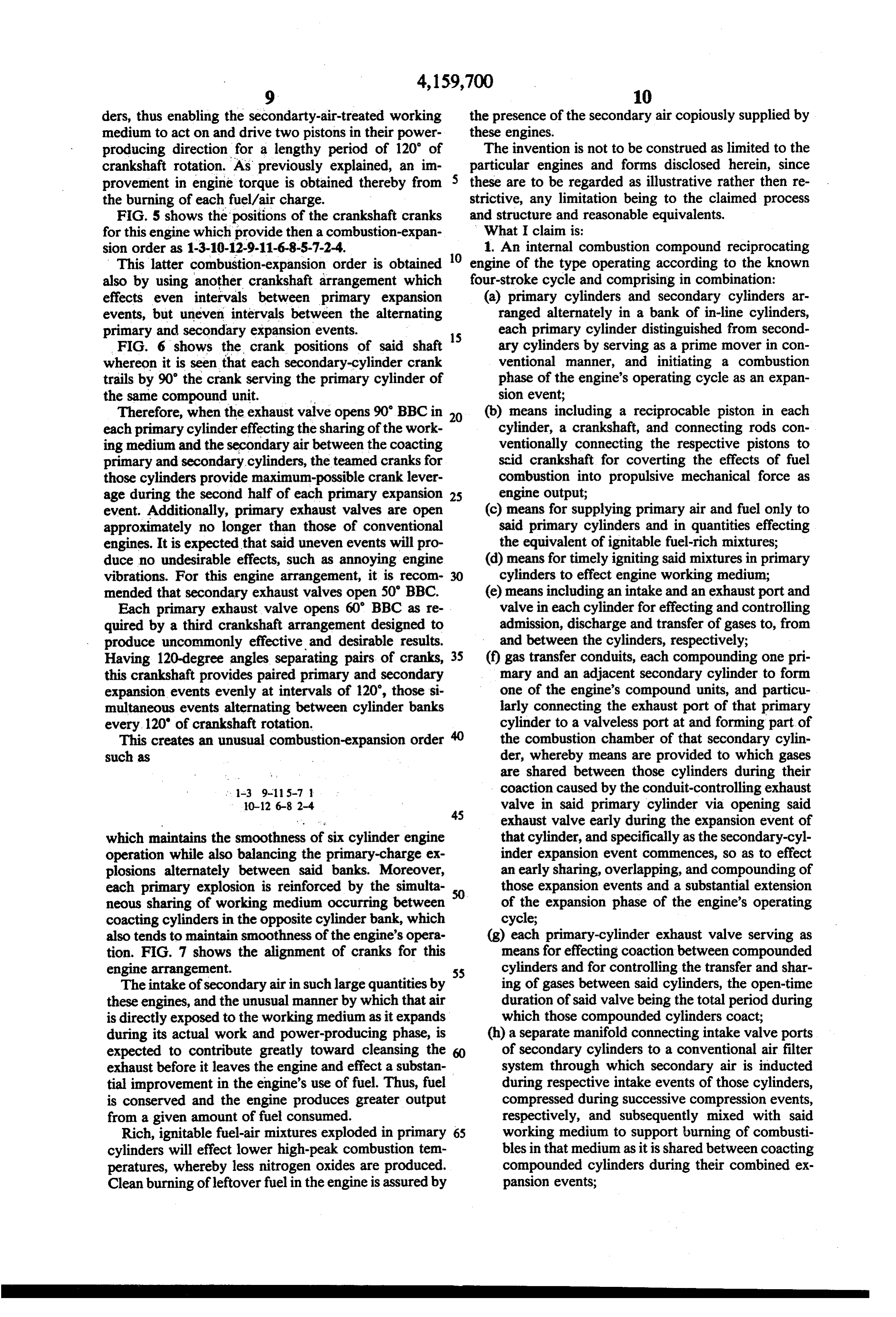
Page 11
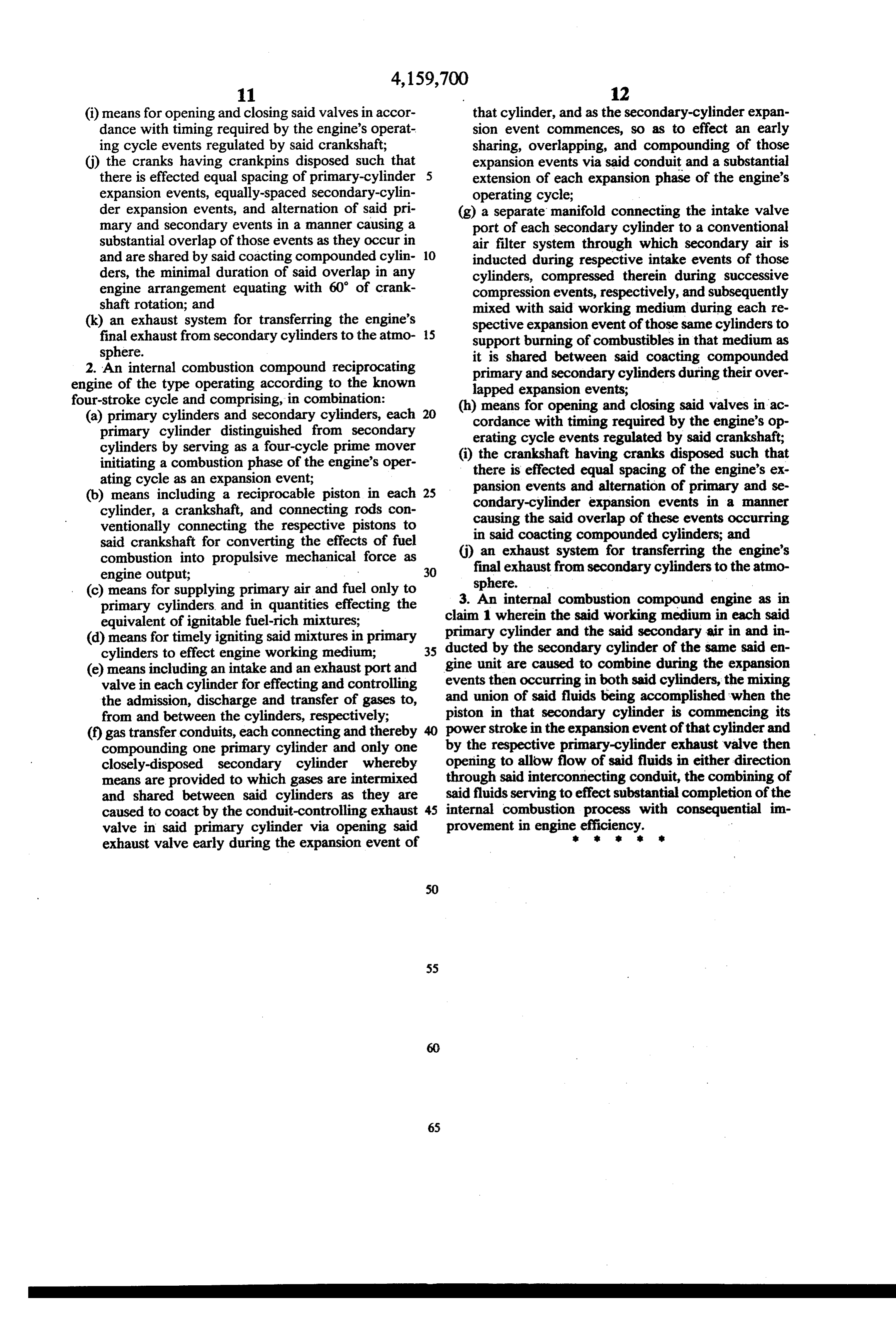
(i) means for opening and closing said valves in accor that cylinder, and as the secondary-cylinder expan dance with timing required by the engine's operat sion event commences, so as to effect an early ing cycle events regulated by said crankshaft; sharing, overlapping, and compounding of those (j) the cranks having crankpins disposed such that expansion events via said conduit and a substantial there is effected equal spacing of primary-cylinder extension of each expansion phase of the engine's expansion events, equally-spaced secondary-cylin operating cycle;
der expansion events, and alternation of said pri- (g) a separate manifold connecting the intake valve mary and secondary events in a manner causing a port of each secondary cylinder to a conventional substantial overlap of those events as they occur in air filter system through which secondary air is and are shared by said coacting compounded cylin- 10 inducted during respective intake events of those ders, the minimal duration of said overlap in any cylinders, compressed therein during successive engine arrangement equating with 60 of crank- compression events, respectively, and subsequently shaft rotation; and mixed with said working medium during each re (k) an exhaust system for transferring the engine's spective expansion event of those same cylinders to final exhaust from secondary cylinders to the atmo- 15 support burning of combustibles in that medium as sphere. it is shared between said coacting compounded 2. An internal combustion compound reciprocating primary and secondary cylinders during their over engine of the type operating according to the known lapped expansion events; four-stroke cycle and comprising, in combination: a in ar (a) primary cylinders and secondary cylinders, each 20 (ISEE. E. E. primary cylinder distinguished from secondary erating cycle event ted sd cranksh cylinders by serving as a four-cycle prime mover (i) the iaft in crani i. C such that initiating a combustion phase of the engine's oper- there is effected equal spacing of E. . exis ating cycle as an expansion event; ts and alternation of pri d (b) means including a reciprocable piston in each 25 pansion events andexpansion condary-cylinder rnationevents of primary and se in a manner cylinder, a crankshaft, and connecting rods con- o he said fth ventionally connecting the respective pistons to causing the said overlap of these events occurring said crankshaft for converting the effects of fuel in said coacting compounded cylinders; and s combustion into propulsive mechanical force as (j) an exhaust system for transferring the engine's engine output; 30 final exhaust from secondary cylinders to the atmo (c) means for supplying primary air and fuel only to sphere. . primary cylinders and in quantities effecting the 3. An internal combustion compound engine, as in equivalent of ignitable fuel-rich mixtures; claim 1 wherein the said working medium in each said (d) means for timely igniting said mixtures in primary primary cylinder and the said secondary air in and in cylinders to effect engine working medium; 35 ducted by the secondary cylinder of the same said en (e) means including an intake and an exhaust port and gine unit are caused to combine during the expansion valve in each cylinder for effecting and controlling events then occurring in both said cylinders, the mixing the admission, discharge and transfer of gases to, and union of said fluids being accomplished when the from and between the cylinders, respectively; piston in that secondary cylinder is commencing its (f) gas transfer conduits, each connecting and thereby 40 power stroke in the expansion event of that cylinder and compounding one primary cylinder and only one by the respective primary-cylinder exhaust valve then closely-disposed secondary cylinder whereby opening to allow flow of said fluids in either direction means are provided to which gases are intermixed through said interconnecting conduit, the combining of and shared between said cylinders as they are said fluids serving to effect substantial completion of the caused to coact by the conduit-controlling exhaust 45 internal combustion process with consequential im valve in said primary cylinder via opening said provement in engine efficiency.
exhaust valve early during the expansion event of
Page 12
- UNITED STATES PATENT AND TRADEMARK OFFICE
CERTIFICATE OF CORRECTION
INVENTOR(S) : William H. McCrum it is Certified that error appears in the above-identified patent and that said Letters Patent are hereby Corrected as shown below:
From the front-page section headed "Related U.S. Application Data," delete "Continuation-in-part of Ser. No. 734, 638, Oct. 18, 1976, Pat. No. 4,086,882' and insert -- Continuation in-part of Ser. No. 846,579, Oct. 28, 1977, Pat. No. 4,159,699,
Column 8, line 24, 'element' should read -- medium -- . Column 8, 1ine 27, 'are' should read -- and r - . Column 10, line 22, "coverting" should rewd -- converting --. Column 11, 1ine 4, in paragraph (j), 'the cranks having crankpins' should read -- the crankshaft having cranks -- . signed and Sealed this
Twenty-seventh D 2 y of Nopenber 1979
SEAL
Attest:
LUTRELLE F. PARKER
RUTH C. MASON
Attesting Officer Acting Commissioner of Patents and Trademarks
Provenance
- Collection
- Cited prior art
- Original PDF
- patentimages.storage.googleapis.com →
- Filed
- 1978-05-01
- Pages
- 12
- Method
- pdftotext (the PDF's own text layer) + pdftoppm 300dpi page scans
- Source
- Google Patents bibliographic record
- Granted
- 1979-07-03
- Inventors
- William H. McCrum
- Transcribed from
- patentimages.storage.googleapis.com →