patent · US4570578
Method and device for operating a hydrogen motor
18 February 1986
Page 1 — bibliographic record
United States Patent (19) 11 Patent Number: 4,570,578 Peschka et al. 45 Date of Patent: Feb. 18, 1986 (54) METHOD AND DEVICE FOR OPERATING A 4,276,749 7/1981 Crowley ................................. 62/S1 HYDROGEN MOTOR 4,406,129 9/1983 Mills .......................................... 62/7
FOREIGN PATENT DOCUMENTS
75) Inventors: Walter Peschka, Sindelfingen;
Gottfried Schneider; Willi 2443815 4/1976 Fed. Rep. of Germany . Nieratschker, both of Stuttgart, all of 2717761 11/1977 Fed. Rep. of Germany . Fed. Rep. of Germany 2133480 7/1984 United Kingdom .................. 417/32 73) Assignee: Deutsche Forschungs- und Primary Examiner-E. Rollins Cross Versuchsanstalt fir Luft- und Attorney, Agent, or Firm-Kenway & Jenney
Raumfahrt e.V., Bonn, Fed. Rep. of
Germany (57) ABSTRACT 21 Appl. No.: 673,997 A method and apparatus is provided for propelling a hydrogen engine with cryogenically stored hydrogen, 22 Filed: Nov. 21, 1984 wherein a pump, cooled down to an operating tempera 30 Foreign Application Priority Data ture close to the hydrogen boiling point, feeds hydro Nov. 25, 1983 IDE Fed. Rep. of Germany ....... 3342582 gen to the fuel-injection hydrogen engine. In order to improve the method and the apparatus so that the pump 51) Int. Cl. .............................................. F02B 75/12 need not be maintained constantly at the operating ten 52 U.S. C. ........................... 123/1 A; 123/DIG. 12; perature, it is proposed that the pump, when its temper 123/27 GE; 62/51 ature exceeds its operating temperature level, be purged 58) Field of Search ......... 123/1 A, DIG. 12, 27 GE; with cold hydrogen gas and thus cooled down until its 62/7, 51,514 R; 417/366, 368, 32 temperature drops to the operating level, and that the 56) References Cited hydrogen gas that has been passed through the pump be
range.
2,518,597 8/1950 Brooks .................................. 417/32 3,565,201 2/1971 Petsinger .... ... 62/7 4,080,800 3/1978 Spaulding et al. ...................... 62/51 9 Claims, 1 Drawing Figure
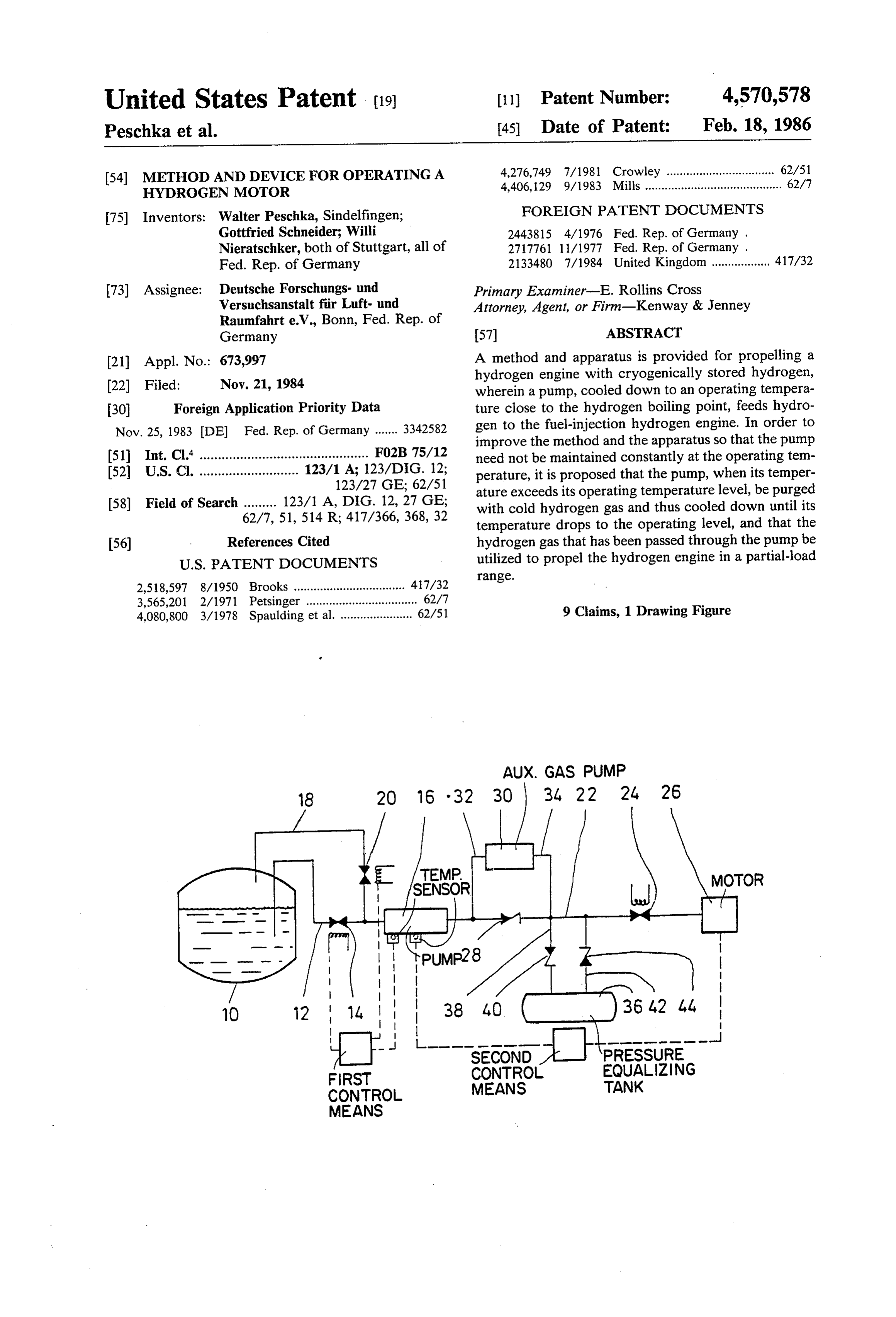
AUX. GAS PUMP
18 2O 16 - 32 30 34 22 24, 26
TEMP
1N F 55. ) MOTOR
10 12 4 40 ( )3642 44
FIRST CONTROL EQUALIZING
CONTROL MEANS TANK
MEANS
Page 2
Drawing sheet — no readable text.
Page 3
pump and the pump cooled thereby to operating tem
METHOD AND DEVICE FOR OPERATING A perature.
HYDROGEN MOTOR This object is solved in accordance with the inven tion with a method of the above described type in such
This invention relates to a method for operating a 5 a way that the pump, at a higher temperature than its hydrogen motor with cryogenically stored hydrogen, operating temperature, is passed through (purged) by whereby hydrogen is fed to the hydrogen motor, driven cold hydrogen gas and thereby cooled until its operat by fuel injection, by means of a pump which is cooled to ing temperature is attained, and that the hydrogen operating temperature which is in the range of the boil motor is driven with the hydrogen gas, which has ing point of hydrogen. 10 passed through the pump, in a partial-load range. Furthermore, the invention relates to a device for The advantage of this method is in that the motor can carrying out the method with a cryotank for liquid also be driven or started when the pump is warm and, at hydrogen and a pump, having an inlet and an outlet the same time, the pump can be cooled to operating opening, whose inlet opening is connected with the temperature, so that it is no longer necessary to main liquid hydrogen in the cryotank and whose outlet open 15 tain the pump at operating temperature even when the ing is provided with a feed pipe leading to a hydrogen hydrogen motor is shut off.
motor. With one embodiment of the invention, it is advanta With hydrogen motors, mixture formation can take geous when the hydrogen gas is pumped through the place in various ways. The simplest possibility is carbu pump to the hydrogen motor by means of an auxiliary retion whereby, as with a conventional carburetor en 20 gas pump. The auxiliary gas pump makes it possible to gine, a mixture of air and fuel, that is, in this case, air and easily pump hydrogen to the hydrogen motor, driven in hydrogen, is drawn in, compressed and subsequently the partial-load range, and to compress it to the required burned. To accomplish this, hydrogen must be fed to pressure.
the motor at a pressure of approximately 1 to 2 bar. Moreover, it can be advantageous with an embodi Another possibility is low-pressure fuel injection, ment of the method, if, in the event the pump is at a whereby the motor draws in air and whereby, at the temperature start of a compression phase in the vicinity of a bottom drogen motorabove its operating temperature, the hy dead center, hydrogen is injected. This requires injec that, when the operatingwith is driven advanced injection and temperature of the pump is tion pressure in the range of approximately 5 to 10 bar. attained, the hydrogen motor is switched to fuel injec Compared to the above-noted methods, a greater motor 30 tion. With this method, the hydrogen output is attained with high-pressure fuel injection. In motor does not have to be compressedgastofor driving the this case, hydrogen is only injected toward the end of a sures necessary for fuel injection while thehigh the pres pump is compression cycle, that is, in the area of the top dead being cooled. This considerably facilitates the pumping center. With this injection, which is similar to a diesel operation, injection pressures in the range of 30 to 100 35 of the hydrogen. Thus, for example, when using an auxiliary gas pump, it no longer has to be a high-pres bar and more are required.
To drive a hydrogen motor with fuel injection, a sure pump, instead, a considerably simpler and less method and a device are known with which liquid hy expensive low model is sufficient which can produce the drogen stored in the cryotank is conveyed by means of necessary pressure.
a pump which has been cooled to a temperature in the high-pressure pump,possible 40 It is, moreover, to use the liquid hydrogen which is at a temperature above its range of the liquid hydrogen, in this case, a liquid hy operating temperature, to produce the required pres drogen high-pressure pump, so that the hydrogen, sure, which, indeed, which is under high pressure, can be fed to the hydro pressure due to sealing problems, cannot compress hydrogen to high gen motor for fuel injection. however, is able to The disadvantage of the known method is in that the 45 produce the pressure required for advanced injection. pump, even when the hydrogen motor is shut off, is With a further embodiment of the method, it is advan constantly maintained at operating temperature, i.e. at tageous that, in the event the pump is at a temperature temperatures in the range of the boiling point of liquid above its operating temperature, the hydrogen motor is hydrogen. driven with carburetion and that, when the operating With the device for carrying out the known method, 50 temperature motor is of the pump is attained, the hydrogen switched to fuel injection. Driving the hydro the pump is located directly in the cryotank for liquid hydrogen, so that it is constantly at operating tempera gen motor with carburetion during the cooling phase of ture. The result of this is that, due to the required large the pump enables the use of the liquid hydrogen high openings in the cryotank for inserting the pump, install pressure pump functioning above operating tempera ing of heat insulation of the cryotank becomes more 55 ture, a very simple and inexpensive auxiliary gas pump difficult and that, due to the required feed lines for or no pump at all to produce the necessary low hydro driving and controlling the pump, additional thermal gen pressure, whereby, in the latter instance, the re bridges, which lead into the liquid hydrogen, result. quired pressure is produced by the liquid hydrogen This results in a relatively high evaporation rate of the evaporating in the cryotank.
cryotank. 60 Further, it is the object of the invention to create a Moreover, when the pump is built into the cryotank, device for carrying out the method.
adjustments during operation are considerably more This object is solved according to the invention with difficult and servicing is only possible after the pump a device of the above described type in that the pump is has been removed from the cryotank. located outside of the cryotank and that an intake pipe, It is the object of the invention to improve the ge 65 extending from the inlet opening, separates into a first neric type method in such a way that the pump does not intake pipe for liquid hydrogen and into a second intake have to be constantly maintained at operating tempera pipe, provided with a valve means, for hydrogen gas, ture, so that the motor can also be driven with a warm which both lead into the cryotank.
Page 4
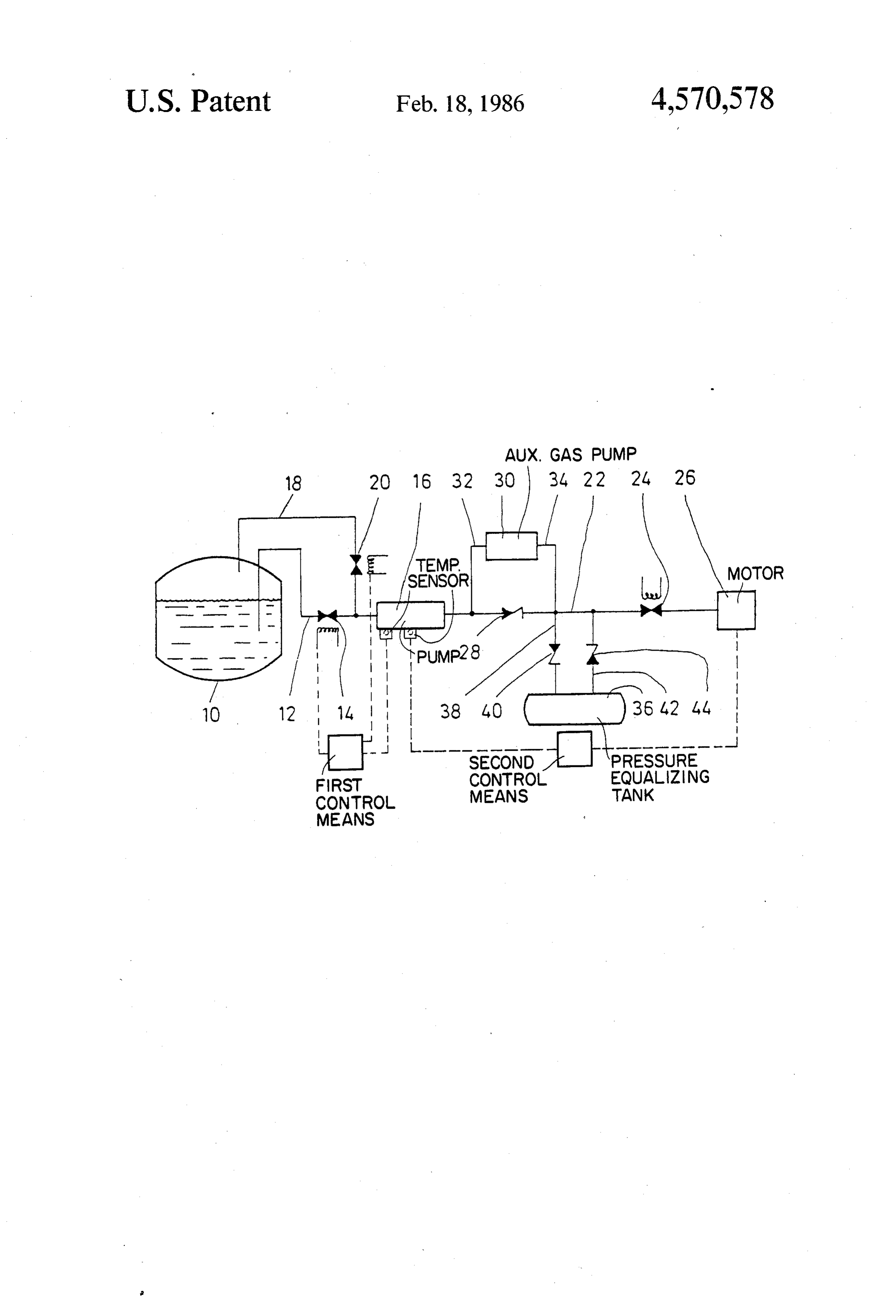
The advantage of this device lies in that, when a tween the liquid hydrogen high-pressure pump 16 and pump is positioned outside the cryotank, the evapora the check valve 28 and the pressure pipe 34 discharges tion rate of the tank is substantially lower due to a better into the feed pipe 22 between the check valve 28 and the insulation of the tank and a smaller number of thermal valve 24. To balance fluctuations of pressure, a pressure bridges leading into the tank. In addition, with this equalizing tank 36 is provided between check valve 28 arrangement, the liquid hydrogen high-pressure pump and valve 24, parallel to the feed pipe 22. This pressure is substantially more easily accessible for adjustments equalizing tank 36 has a feed pipe 38, which branches and servicing. off from the feed pipe 22 and has a check valve 40, as With a preferred embodiment, it is provided that the well as a return pipe 42, which leads to the feed pipe 22 first intake pipe has a valve means. This offers the ad 10 and also has a check valve 44.
vantage that it is ensured, when the hydrogen gas is Several possibilities are conceivable for starting the drawn in for cooling the pump, that no liquid hydrogen liquid hydrogen high-pressure pump 16 and the auxil is drawn in. iary gas pump 30. Thus, for example, a hydraulic drive With a further embodiment, it is advantgeous when a mechanism, driven by the hydrogen motor 26, is pro first control means is provided which, in the event the 15 vided for the liquid hydrogen high-pressure pump 16. It pump is at a temperature above its operating tempera is, however, also possible that the liquid hydrogen high ture, closes the valve in the first intake pipe and opens pressure pump 16 and the auxiliary gas pump 30 are the valve in the second intake pipe, and which, in the electrically driven.
case when the pump is at operating temperature, opens The valve 14 in the first intake pipe 12, valve 20 in the the valve in the first intake pipe and closes the valve in 20 second intake pipe 18, as well as valve 24 in the feed the second intake pipe. This control means guarantees pipe 22 can be operated in various ways. For example, that either only gaseous or only liquid hydrogen is valves 14, 20, 24 can be electromagnetically operable, drawn in from the cryotank. i.e. these are then solenoid valves. It is furthermore advantageous that a second control If the liquid hydrogen high-pressure pump 16 is at a means be provided which, in the case when the pump is 25 temperature above operating temperature, then valve at a temperature above its operating temperature, 14 in the first intake pipe 12 is closed and valve 20 in the switches the hydrogen motor to advanced injection or second intake pipe 18 is opened. By switching the auxil carburetion and, when the operating temperature is iary gas pump 30 on, hydrogen gas is now drawn in attained, switches to fuel injection. from the gas bubble located above the liquid hydrogen With a further embodiment, it is provided that a one 30 in the cryotank 10. It flows through the second intake way circuit with a check valve, pervious only in direc pipe 18, the opened valve 20, the liquid hydrogen high tion of the hydrogen motor, and, parallel thereto, an pressure pump 16, feed pipe 22 and suction pipe 32 to auxiliary gas pump are arranged in the feed pipe. The the auxiliary gas pump 30 and thereby cools the liquid advantage of the auxiliary gas pump lies in that, in the hydrogen high-pressure pump 16.
event the pump is at a temperature above its operating 35 The auxiliary gas pump 30 produces the necessary temperature, the pressure of the hydrogen gas required pressure for the mixture formation which is used in each for operating the hydrogen motor can be easily pro case in the hydrogen motor 26, i.e. with fuel injection, a duced with it. Moreover, the one-way circuit has the pressure of 30 to 100 bar and more, with advanced advantage that, when the working pump is at operating injection, a pressure of 5 to 10 bar and with carburetion temperature, the hydrogen does not flow through the a pressure of 1 to 2 bar. After opening the valve 24 in no longer necessary auxiliary gas pump but, instead, is feed pipe 22, the compressed hydrogen gas can flow led through the one-way circuit past the auxiliary gas through the pressure line 34 via feed pipe 22 to hydro pump to the hydrogen motor. gen motor 26, Possible fluctuations of pressure are bal Additional features and advantages of the invention anced by the pressure equalizing tank 36. become evident from the following description as well 45 The check valve 28, arranged parallel to the auxiliary as from the attached drawing of an embodiment of the gas pump 30 in the feed pipe 22, prevents, with this invention. The drawing is a schematic representation of method of operation, that the auxiliary gas pump 30 is a device according to the invention. short-circuited and not able to produce the required a first intake pipe 12, dipping into the liquid hydrogen pressure.
and having a valve 14, leads from a cryotank containing 50 During the cooling process, the liquid hydrogen liquid hydrogen to an inlet opening of a liquid hydrogen high-pressure pump 16 can be switched on or off. When high-pressure pump 16. A second intake pipe 18 for the liquid hydrogen high-pressure pump 16 is switched gaseous hydrogen, having a valve 20, dips into a gas off, it is, however, necessary that valves and plunger are bubble of hydrogen, which is located above the liquid constructed in such a way that the liquid hydrogen hydrogen in the cryotank 10, and discharges between 55 high-pressure pump 16 has almost no or only a very valve 14 of the first intake pipe 12 and the inlet opening slight resistance to flow in conveying direction and can of the liquid hydrogen high-pressure pump 16 into the thus be purged and cooled by the cold hydrogen gas first intake pipe 12. drawn in through the auxiliary gas pump 30. It is, how A feed pipe 22, extending from an outlet opening of ever, also conceivable that the liquid hydrogen high the liquid hydrogen high-pressure pump 6 and having a 60 pressure pump 16, although it is at a temperature above valve 24, leads to a hydrogen motor 26. its operating temperature, is switched on, however, due Between the outlet opening of the liquid hydrogen to the thermal expansion of plunger and valves, can high-pressure pump 16 and valve 24, a check valve 28, only produce a slight pressure and functions as fore which is pervious only in direction of the hydrogen pump for the auxiliary gas pump 30.
motor 26, and, parallel to this check valve, an auxiliary 65 As soon as the operating temperature of the liquid gas pump 30, having a suction pipe 32 and a pressure hydrogen high-pressure pump 16 is attained, valve 20 in pipe 34 are arranged in the feed pipe 22, whereby the the second intake pipe for gaseous hydrogen is closed, suction pipe 32 branches off from the feed pipe 22 be valve 14 of the first intake pipe 12 is opened, the liquid
Page 5
hydrogen high-pressure pump 16 switched on and the by passing cold hydrogen gas through the pump until auxiliary gas pump 30 switched off. Liquid hydrogen is the operating temperature is attained and driving therewith drawn in by the liquid hydrogen high-pres the hydrogen motor with the hydrogen gas which sure pump 16 from the cryotank 10 via the first intake 5 has passed through the pump, in a partial-load pipe 12 and thus hydrogen under high pressure is pro range.
duced which flows through the feed pipe 22, through the hydrogenaccording 2. Method to claim 1, characterized in that gas is pumped through the pump to the the check valve 28 located in it and valve 24 to the hydrogen motor 26 driven with fuel injection. hydrogen motor by means of an auxiliary gas pump. 3. Method according to claim 1 or 2, characterized in
When the hydrogen motor 26 is shut off, the valve 24 O that, is simultaneously closed, so that hydrogen, which is still aboveinitsthe event that the pump is at a temperature operating temperature, the hydrogen motor is under high pressure, is stored in the pressure equalizing driven with advanced tank 36. This is sufficient in order to, after short stop erating temperature ofinjection the pump and that, when the op is attained, the hydro pages during which the liquid hydrogen high-pressure gen motor is switched over to fuel pump 16 does not warm up, immediately start the hy 15 4. Method according to claim 1 orinjection. 2, characterized in drogen motor 26 with fuel injection and hydrogen feed that, in the event the pump is at a temperature which is ing by means of the liquid hydrogen high-pressure above its operating temperature, the hydrogen motor is pump 16, without the necessity of having to switch the driven with carburetion and that, when the operating auxiliary gas pump 30 on as well. temperature of the pump is attained, the hydrogen In a variation of the embodiment shown in the draw 20 motor is switched to fuel injection. ing, the auxiliary gas pump 30 can be omitted if the 5. Hydrogen motor with cryogenically stored hydro hydrogen motor 26, in the event that the liquid hydro gen conveyed to the motor via a pump which is cooled gen high-pressure pump 16 is at a temperature above its to an operating temperature which is in the range of the operating temperature, is driven with advanced injec boiling point of hydrogen by passage of cold hydrogen tion or carburetion. The hydrogen pressures required 25 gas, a cryotank for liquid hydrogen and a pump having with these two types of mixture formation can also be an inlet and outlet opening, whose inlet opening is con produced by the liquid hydrogen high-pressure pump nected with the liquid hydrogen in the cryotank and 16, operating out of its optimum performance, so that, whose outlet opening is provided with a feed pipe lead after attaining the operating temperature of the liquid ing to a hydrogen motor, characterized in that the pump hydrogen high-pressure pump 16, only switching the 30 (16) is positioned outside the cryotank (10) and that an hydrogen motor 26 from advanced injection or carbure intake pipe, extending from the inlet opening, separates tion to fuel injection and closing valve 20 in the second into a first intake pipe (12) for liquid hydrogen and into intake pipe 18 for gaseous hydrogen, as well as opening a second intake pipe (18), provided with a valve means (20), for hydrogen gas, both intake pipes leading into valve 14 in the first intake pipe 12 for liquid hydrogen, 35 the are required. cryotank (10).
If the hydrogen motor 26, in the event the liquid 6. Device according to claim 5, characterized in that hydrogen high-pressure pump 16 is at a temperature the7.first intake pipe (12) has a valve means (14). Device according to claim 5 further comprising above its operating temperature, is only driven with temperature sensing means characterized in that a first carburetion, then the pressure in the hydrogen gas phase, resulting in the cryotank 10 by evaporating hy control means is provided which, in the event the pump (16) is at a temperature which is above its operating ... drogen, is sufficient to drive the hydrogen motor 26, temperature, without it being necessary to switch the liquid hydro (12) and openscloses the the valve (14) in the first intake pipe valve (20) in the second intake pipe gen high-pressure pump 16 on. In order to accomplish (18), as well as in the case this, it is however necessary to construct the liquid 45 operating temperature, said when the pump (16) is at hydrogen high-pressure pump 16 in such a way that the valve (14) in the first intake pipe (12)means control opens the valves and the plunger have only a slight resistance to valve (20) in the second intake pipe (18). closes the and flow in the switched-off position in conveying direction 8. Device according to claim 5 for carrying out the and permit a flow of gas. After the operating tempera method according to claim 3 or 4, further comprising ture of the liquid hydrogen high-pressure pump 16 is 50 temperature sensing means characterized in that a sec attained, the pump 16 is switched on, valve 20 is closed, ond control means is provided which, in the event the valve 14 is opened and the hydrogen motor 26 is pump (16) is at a temperature above its operating tem switched from carburetion to fuel injection. perature, switches the hydrogen motor (26) to ad We claim: vanced injection or carburetion and, when the operat 1. Method for operating a hydrogen motor with cryo 55 ing temperature is attained, switches to fuel injection. genically stored hydrogen comprising conveying hy 9. Device according to claim 5, characterized in that drogen to the hydrogen motor driven by fuel injection a one-way circuit with a check valve (28), pervious only via a pump which is cooled to an operating temperature in direction of the hydrogen motor (26), and, parallel to which is in the range of the boiling point of hydrogen, it, an auxiliary gas pump (30) are arranged in the feed cooling the pump, at a higher temperature than its oper 60 pipe (22). sk k k k is ating temperature,
Provenance
- Collection
- Cited prior art
- Original PDF
- patentimages.storage.googleapis.com →
- Filed
- 1984-11-21
- Pages
- 5
- Method
- pdftotext (the PDF's own text layer) + pdftoppm 300dpi page scans
- Source
- Google Patents bibliographic record
- Granted
- 1986-02-18
- Inventors
- Walter Peschka; Gottfried Schneider; Willi Nieratschker; Deutsches Zentrum fuer Luft und Raumfahrt eV
- Transcribed from
- patentimages.storage.googleapis.com →