patent · US3896774
Staged internal combustion engine with modulating interstage temperature control
29 July 1975
Page 1 — bibliographic record
United States Patent (19) [11] 3,896,774 Siewert (45) July 29, 1975 54 STAGED INTERNAL COMBUSTION 3,805,752 4/1974 Cataldo.......................... 123/59 EC
ENGINE WITH MODULATING
INTERSTAGE TEMPERATURE CONTROL Primary Examiner-Wendell E. Burns 75 inventor: Robert M. Siewert, Birmingham, Assistant Examiner-David D. Reynolds Mich. Attorney, Agent, or Firm-Robert J. Outland 73) Assignee: General Motors Corporation, (57) ABSTRACT Detroit, Mich.
22 Filed: July 5, 1974 A staged internal combustion engine with a bypass heat exchanger in the interstage manifold and a tem (21) Appl. No.: 485,940 perature control valve arranged to modulate the flow of interstage gases between the heat exchanger and bypass passages so as to control the temperature of in 52 U.S. Cl............. 123/59 EC; 123/1 R; 123/52 R terstage gases delivered to the second stage combus (5ll Int. Cl............................................. F02b 75/20 tion chamber. Automatic control means including in a 58) Field of Search.......... 123/119 E, 59 EC, 52 R, preferred embodiment a plurality of expandable bel 123/37, 1 R, 3; 60/39.17 lows are made responsive to various engine operating 56) References Cited conditions, such as the final interstage gas tempera ture, engine speed and engine load to vary the inter
UNITED STATES PATENTS stage gas temperature in a predetermined manner and 1,362,080 12/1920 Chorlton......................... 1231.59 EC maintain desired conditions for efficient second stage 2, 13,601 4/1938 Pratt................................... 12311 R combustion.
2,113,602 4/1938 Pratt................................... 12311 R 3,717, 130 2/1973 Thornburgh.................... 12311 19 A 4 Claims, 3 Drawing Figures
Page 2
Drawing sheet — no readable text.
Page 3
Drawing sheet — no readable text.
Page 4
STAGED INTERNAL COMBUSTON ENGINE WITH timing of second stage ignition when compression or MoDULATING INTERSTAGE TEMPERATURE auto-ignition is utilized. The use of spark ignition in the CONTROL second stage reduces the criticality but does not elimi
FIELD OF THE INVENTION
nate the need for interstage temperature control; since, 5 if the temperature of gas admitted to the second stage
This invention-relates to internal combustion engines is too low, misfiring may occur; while if the tempera of the staged combustion type and more particularly to ture is too high, pre-ignition will occur, resulting in ove means including an automatically controlled bypass radvanced timing and inefficient operation. In addition, heat exchanger for maintaining desired interstage gas some degree of interstage temperature control is neces temperatures in such engines. 10 sary to prevent inefficient thermal reaction in the inter BACKGROUND OF THE INVENTION stage manifold.
It is known in the art to arrange an internal combus SUMMARY OF THE INVENTION tion engine to perform the combustion of a fresh The present invention provides fast responding charge of fuel in two separate sequential working cy 15 means for controlling interstage gas temperatures in cles having separate stages of combustion and each staged internal combustion engines, in order to main yielding an output of work to the engine output shaft, tain such temperatures within desired ranges under The general method of operation of such engines, varying conditions of engine operation. More specifi which I refer to as staged combustion engines, involves cally, the invention provides for modulating control of the admission of a rich air-fuel charge to an engine 20 interstage gas temperatures by the use of a bypass heat combustion chamber wherein it is passed through a exchanger in the interstage manifold with suitable con first stage working cycle including compression, com trol means for modulating the flow on interstage gases bustion and expansion steps. This cycle results in the between the heat exchanger and the bypass passage. delivery of power to the engine output shaft and leaves One feature of a cooling system according to the in a residual charge of combustion products and incom 25 vention is that it provides a dual pass interstage mani pletely burned combustibles. To this charge, air is fold for a staged combustion engine having a heat ex added to form a second and preferably somewhat lean changer in one path while the other path serves as by combustible mixture heavily diluted with burned gases. pass around the heat exchanger. A modulating valve in This mixture is passed through a second stage cycle of the interstage manifold or passage is provided to con compression, combustion and expansion, again yield 30 trol the flow of gases between the heat exchanger and ing work to the engine output shaft. bypass passages.
Such a process is capable of being performed sequen Another feature of the invention is that automatic tially in the same engine combustion chamber. How control means are provided to regulate the position of ever, it is presently believed preferable to utilize sepa the modulating valve in response to various engine op rate combustion chambers of the same engine for per 35 erating conditions so as to maintain desired tempera formance of the two combustion cycles and to transfer tures of interstage gas supplied to the second stage the products resulting from the first stage combustion combustion chamber.
cycle to the second stage combustion chamber through Still another feature of the invention is that the valve a connecting interstage passage, conduit or manifold in 40 control means includes actuating means responsive to which the necessary secondary combustion air is final interstage gas temperature as modulated by means added. responsive to engine speed and load. Various forms of staged combustion engines have Yet another feature of the invention is that the heat been proposed. Among these are the arrangements dis exchanger serves as means for cooling the interstage closed in U.S. Pat. Nos. 2,113,601 and 2,113,602, both 45 gases. Also, the walls of the interstage manifold, except granted Apr. 12, 1938 to N. P. Pratt. Additional forms for the heat exchanger passage, are insulated to prevent and methods of operation of such engines are disclosed excessive loss of heat from the interstage gases directed in my copending U.S. patent application Ser. No. through the bypass passage.
282,390, filed Aug. 21, 1972 and published Jan. 28, These and other features of the invention will be 1975, as B 282,390. more fully understood from the following description In experimental work with staged combustion en SO of certain preferred embodiments taken together with gines operating with gasoline fuel-air mixtures, I have the accompanying drawings.
preferred to utilize conventional spark ignition for initi BRIEF DESCRIPTION OF THE DRAWINGS ating first stage combustion. However, I have found that satisfactory engine operation may be obtained 55 In the drawings:
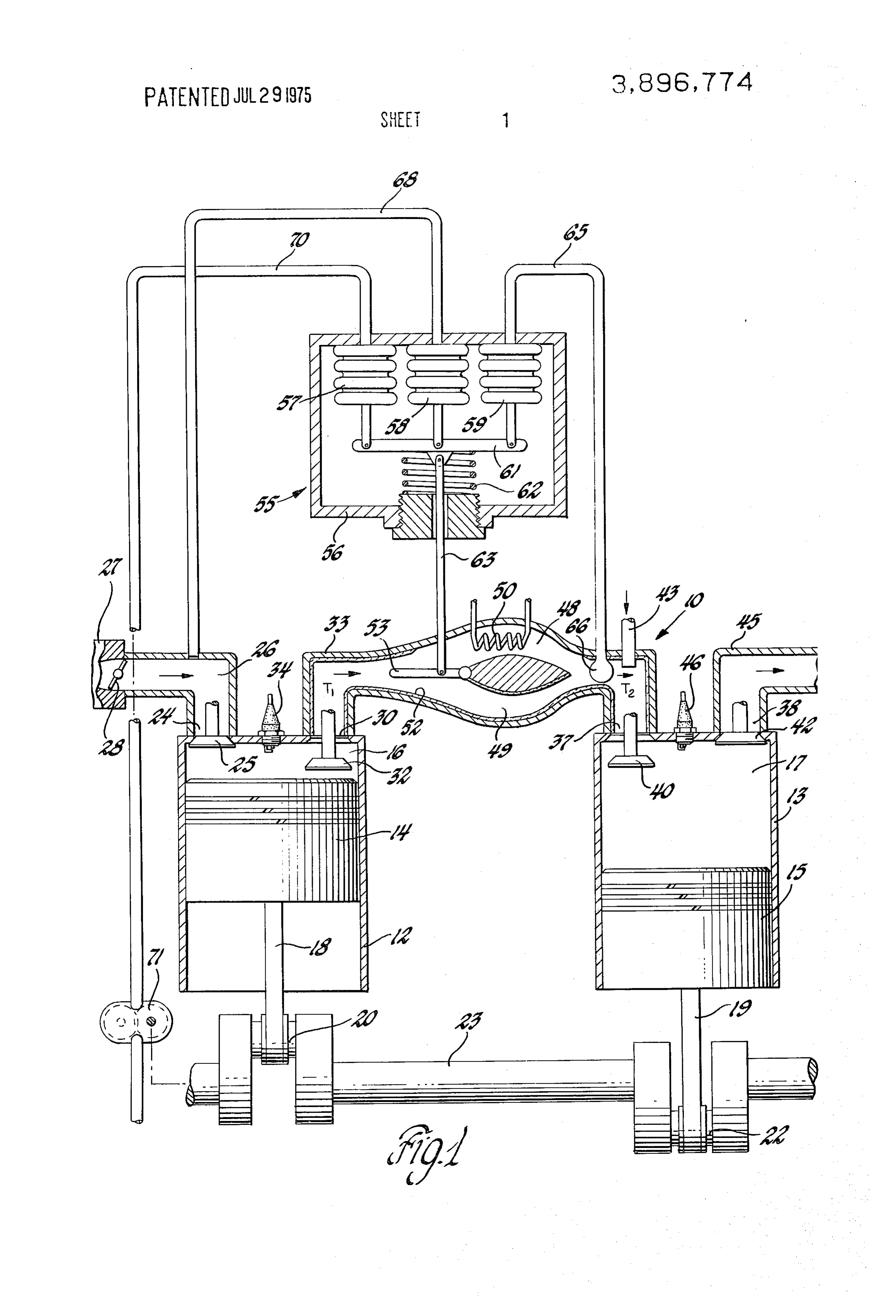
under properly controlled conditions utilizing either FIG. 1 is a diagrammatic view of a staged internal compression ignition or conventional spark ignition for combustion engine having modulating interstage gas initiation of second stage combustion. temperature control means in accordance with the in Both methods of operation have been shown to re vention;
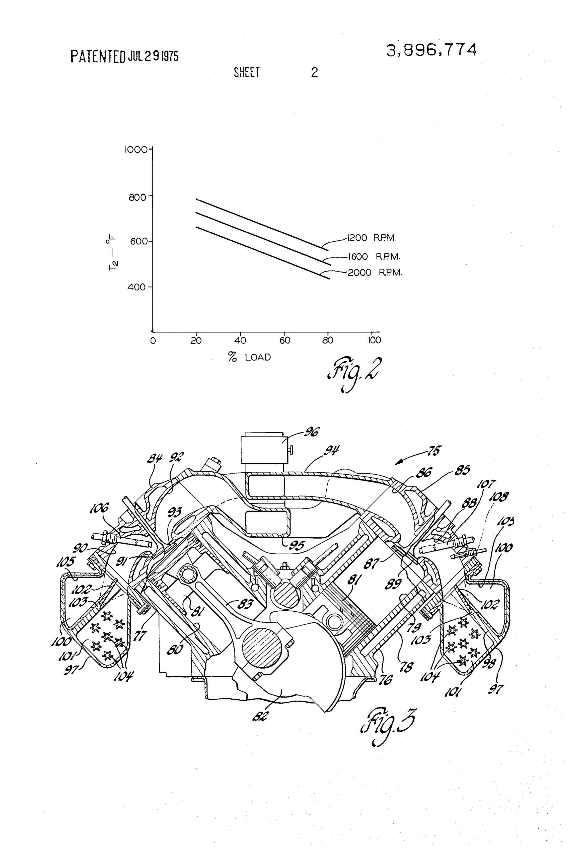
quire some degree of temperature control of the inter FIG. 2 is a graph indicating the relationships of final stage gases in order to maintain engine operation and 60 interstage gas temperature, engine speed and percent efficiency under the varying loads and speeds required of maximum load found desirable for operating a of automotive type engines. For example, my copend staged combustion engine of the type shown in FIG. 1; ing U.S. application Ser. No. 282,390 discloses that in and terstage gas temperatures must be controlled within FIG. 3 is a cross sectional view illustrating a V-8 predetermined ranges which are functions of other en staged combustion engine arrangement including mod gine variables such as engine speed, load and second ulating interstage gas temperature control means in ac stage compression ratio, in order to realize the efficient cordance with the invention.
Page 5
stage combustion chamber 17. Also if desired, both
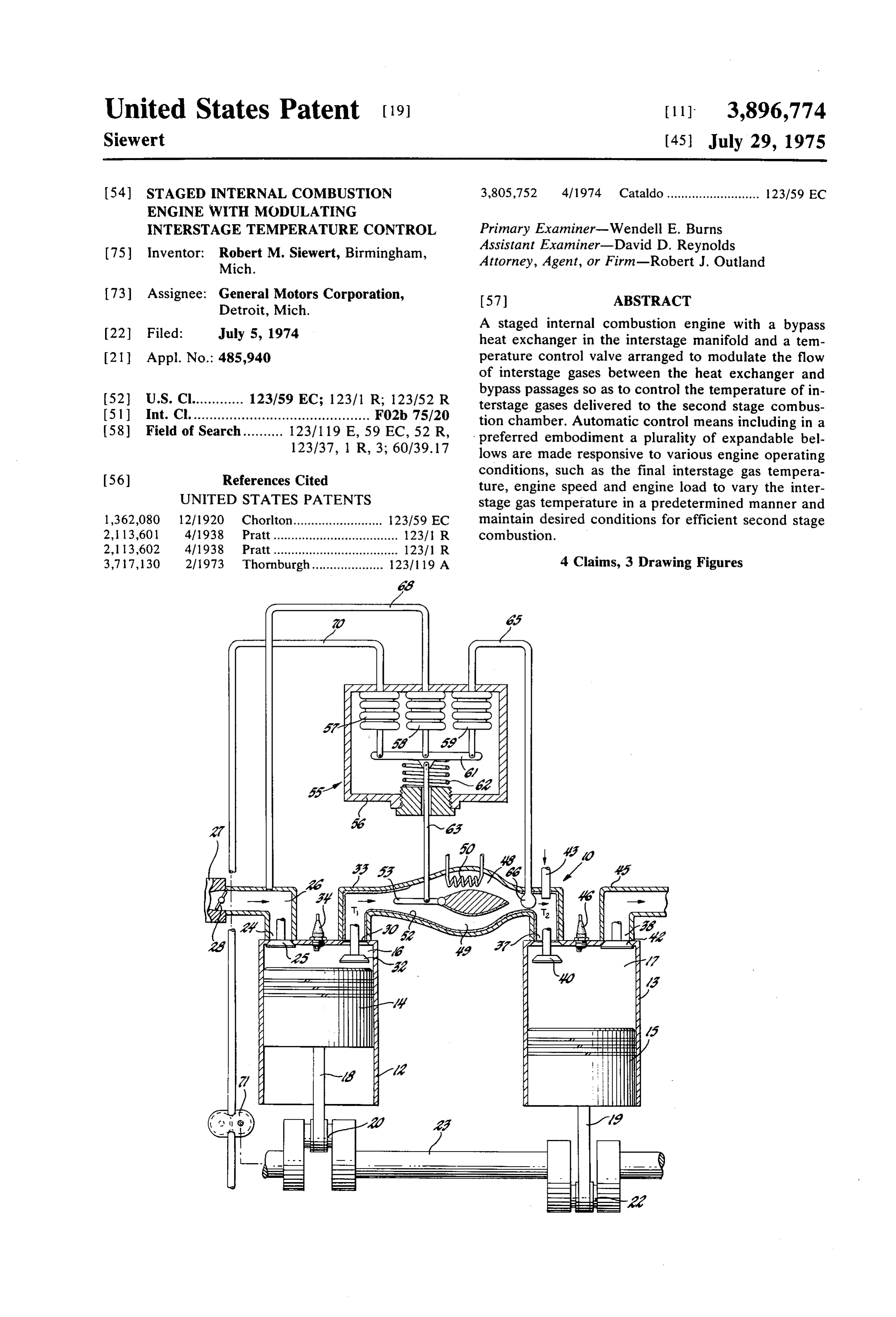
DESCRIPTION OF THE ILLUSTRATED spark and compression ignition could be utilized in the EMBODIMENTS second stage cylinder under varying operating circum Referring first to FIG. 1 of the drawings, numeral 10 stances. If compression ignition is used exclusively, the spark plug 46 could be dispensed with. Further, the generally indicates an internal combustion engine of 5 second stage cylinder could be provided with means, the staged combustion type and having a pair of cylin ders 12, 13 containing reciprocating pistons 14, 15 re such as a movable piston, for varying the compression spectively and defining therewith variable volume ratio of the second stage combustion chamber in order working and combustion chambers 16, 17, respec to assist in controlling the timing of ignition when com tively. Pistons 14, 15 are respectively connected by 10 pression ignition is used.
connecting rods 18, 19 to the oppositely eccentric Also in accordance with my previously mentioned throws 20, 22 of a crankshaft 23. application, suitable means, such as a heat exhanger, Cylinder 12 includes an inlet port 24 controlled by an could be provided in the interstage manifold 33 to con inlet poppet valve 25 and connected through an inlet trol the temperature of the interstage gases in the man manifold or conduit 26 with a source of air and fuel 15 ner required for proper operation of the engine. In gen mixture, such as a carburetor 27, having a throttle 28. eral, such control involves maintaining the temperature Cylinder 12 also includes an exhaust or outlet port 30 of the interstage gases delivered to the second stage controlled by an exhaust poppet valve 32 and connect cylinder within predetermined temperature ranges suit ing with an interstage manifold or conduit 33. A spark able for various engine operating conditions so that plug 34 is provided in the cylinder 12 to ignite combus 20 misfiring due to excessively cold temperatures and pre tible fuel mixtures in the combustion chamber 16. ignition due to excessively high temperatures are both Cylinder 13 includes inlet and exhaust ports 37, 38 avoided. In addition, it is desirable to maintain inter controlled respectively by an inlet poppet valve 40 and stage gas temperatures below a predetermined level to an exhaust poppet valve 42. Inlet port 37 connects 25 avoid undesired reaction of combustibles in he inter through the interstage manifold 33 and exhaust port 30 stage gases with the secondary combustion air added in with the combustion chamber 16 of cylinder 14. An air the interstage manifold.
admission pipe 43 extends into the interstage manifold In accordance with the present invention, control of 33 at a point adjacent the second stage inlet port 37 to interstage gas temperatures may be accomplished by provide secondary combustion air for mixture with the 30 the novel means and methods hereinafter described. interstage gases supplied to the second stage combus The interstage manifold 33 is in part provided with dual tion chamber 17. An exhaust conduit 45 connects with gas flow passages 48, 49 extending in parallel relation the exhaust port 38 to carry away the second stage ex ship and connected intermediate the ends of the mani haust gases. A spark plug 46 is provided in cylinder 13 fold 33. A fluid heat exchanger 50 is disposed within to ignite combustible fuel mixtures in the combustion 35 passage 48 in heat exchange relation with the gases chamber 17. passing therethrough. Heat exchanger 50 may be con The operation of the engine portions so far disclosed nected with any suitable source of coolant, such as air is as follows: from an engine driven air pump, engine cooling water Upon rotation of the crankshaft, pistons 14 and 15 supplied by an engine driven water pump, or another reciprocate in their respective cylinders in timed rela suitable coolant source. Additionally, or alternatively if tion with the valves so as to cause the combustion 40 desired, the heat exchanger 50 may be connected with chambers 16, 17 to cyclically perform four-stroke cy a source of hot fluid for heating the interstage gases cles, including the steps of intake, compression, expan under certain conditions.
sion and exhaust. Carburetor 27 supplies air-fuel mix Passage 49 extending in parallel with the passage 48 tures, preferably rich in fuel, to the inlet manifold 26 45 acts as a bypass around the heat exchanger 50, permit which are admitted in amounts controlled by the throt ting the flow of interstage gases from the first to the tle 28 to the combustion chambers 16 on the intake second stage combustion chambers either through or strokes of piston 14. Here the charges are compressed, around the heat exchanger. The walls of the interstage ignited by the spark plug 34, burned and expanded, de manifold passages may be insulated as at 52 by any suit livering power to the crankshaft. able insulating material. As shown however, the walls The remaining gases consisting of combustion prod 50 of passage 48 need not be insulated when the heat ex ucts and residual combustibles which there was insuffi changer 50 is utilized to cool the interstage gases, since cient air to burn in the first stage are exhausted on the heat loss through the wall of this passage in effect adds exhaust strokes of piston 14 into the interstage mani to the cooling capacity of the heat exchanger. fold 13. Here secondary air is added through air admis 55 Manifold 33 is additionally provided with a pivotally sion pipe 43 which mixes with the first stage exhaust mounted vane 53 which is movable within the manifold gases to form heavily diluted and preferably somewhat between extreme positions, blocking the flow of inter lean combustible mixtures that are admitted to the sec stage gases through one of the flow passages 48, 49. ond stage combustion chamber 17 on the intake The vane 53 thus acts as a modulating valve controlling strokes of piston 15. These charges are then com 60 the amount of gas directed past the heat exchanger 50 pressed, ignited by the spark plug 46, burned and ex and thereby controlling the degree of cooling or other panded in chamber 17, with the resultant delivery of heat transfer applied to the interstage gases. power to the crankshaft. Subsequently, exhaust valve FIG. 2 indicates a desired relationship of final inter 42 is opened and the burned gases are exhausted stage gas temperature, before the addition of supple through exhaust conduit 45. 65 mentary air through pipe 43, to the other operating As disclosed in my previously mentioned application conditions of engine speed and percent of maximum Ser. No. 282,390, the engine may also be operated, uti load which tests indicated were suitable for proper op lizing compression ignition of charges in the second eration of a specific embodiment of an engine of the
Page 6
S 6 type described. While the specific numerical values bellows 57 and further opening valve 53. This has the may vary in particular engine embodiments, the figure effect of lowering the effective control temperature of indicates generally that as engine speed and/or load are the system in the desired degree as indicated by the increased, the final interstage gas temperature must be FIG. 2. In like manner, an increase in engine load reduced in order to maintain the desired operating con caused by opening the throttle 28 reduces the manifold ditions. If the interstage temperature is allowed to ex vacuum, causing an increase in the absolute pressure in ceed the desired levels, pre-ignition of the charge in the bellows 58, thereby causing further opening of the second stage cylinder may occur with resultant loss of valve 53 to increase the cooling of the gases in the de engine efficiency. gree desired.
To maintain the desired interstage gas temperatures 10 In the foregoing manner, the control system senses with the heat exchanger 50 operating as a cooling de the engine operating conditions of final interstage gas vice, the invention provides for the use of automatic temperature, engine speed and engine load and modu control means for modulating the position of the valve lates the interstage gas temperature to maintain the de 53 in accordance with the cooling requirements under sired temperature for proper engine operation. The re the various operating conditions. In the embodiment of 15 sponse of the system is very fast depending mainly on FIG. 1, the control means take the form of a control the ability of the control system to respond to changing unit 55 having a housing 56 containing three expand engine conditions and move the valve 53 accordingly. able bellows members 57, 58 and 59, each having one Movement of the valve immediately changes the rela end mounted on the housing 56. The free ends of the tive amounts of interstage cases passing through and bellows are connected to a reaction bar 61 which is bi 20 around the heat exchanger and thus has an immediate ased by a spring 62 in a direction to compress the bel effect on final interstage gas temperature. The masses lows 57, 58, 59. Bar 61 connects through an actuator of the heat exchanger and the coolant used therein are link 63 with the vane 53 of the modulating control thus eliminated as factors in the response time of the valve in a manner such that the spring 62 biases the system. Accordingly, the invention provides more suit valve 53 in a direction to close off flow to the heat ex 25 able arrangements for varying engine operating condi changer 50. tions than systems wherein the heat exchanger coolant Bellows 59 is connected through a conduit 65 with a temperature is varied to control interstage gas tempera fluid filled bulb 66 located within the interstage mani ture.
fold 33 after the juncture of the passages 48, 49 so as It should be apparent that many other forms of con to be in contact with the mixture of gases passing 30 trol mechanisms could be suitably applied to accom through and bypassing heat exchanger. Bulb 66 may plish essentially the same purposes, and thus the inven contain any suitable temperature responsive fluid tion is not intended to be limited to the specific form which increases in pressure as the temperature is in of mechanism described herein. In addition, as previ creased so as to supply an increasing pressure, tending ously mentioned, the heat exchanger 50 could be uti to expand the bellows 59 upon increasing final inter 35 lized during engine warm-up to provide heat to the in stage gas temperature. terstage gases. However, such action would require a Bellows 58 connects through a conduit 68 with the modification of the control system to permit interstage engine inlet manifold 26 so that as the inlet manifold gas flow through the heat exchanger during the warm pressure increases (vacuum decreases) as occurs on in 40 up period.
creasing engine load, the pressure in the bellows 58 is FIG. 3 shows a staged combustion engine 75 of the increased, tending to expand to the bellows. Bellows 57 eight cylinder V-type having the first and second stage is connected through a conduit 70 with the outlet side cylinders and manifolds arranged in a manner generally of an oil pump 71 which is driven by the engine crank similar to that shown in FIG. 3 of my previously men shaft 23 so that its speed and output pressure vary as 45 tioned U.S. patent application Ser. No. 282,390. En a function of engine speed. Accordingly, increasing en gine 75 includes a cylinder block 76, having two angu gine speed increases the pressure on bellows 57, caus larly disposed banks 77, 78 of cylinders conventionally ing it to tend to expand. arranged in groups of four and including in each bank In operation, the control unit is adjusted so that when two first and two second stage cylinders 79, 80, respec the engine is started the valve 53 is in its bypass posi 50 tively. The cylinders contain conventionally arranged tion, blocking the flow of interstage gases through the pistons 81 connected with a crankshaft 82 by connect heat exchanger 50, as long as the interstage gas temper ing rods 83. The ends of the cylinders are closed by cyl atures are below the desired operating level. In this inder heads 84, 85 containing more or less convention condition, the loss of heat in the interstage manifold is ally arranged ports connecting each cylinder with the minimized by the insulation 52 along the walls of the 55 inner and outer sides of its respective head and con manifold and bypass passage. As the interstage gas tem trolled by a poppet valve. The inwardly opening ports perature increases due to engine operation, the bulb 66 86 connected with each first stage cylinder 79 are uti is heated, causing expansion of the bellows 59 against lized as inlet ports controlled by an inlet valve 87. the force of spring 62 and pivoting the valve 53 down While the outwardly opening ports 88 comprise first wardly in a direction partially opening the passage 48. 60 stage cylinder exhaust ports controlled by exhaust This permits some of the interstage gases to pass valves 89. On the other hand, the outwardly opening through the heat exchanger 50, causing a reduction in ports 90 connected with the second stage cylinders are temperature. Thereafter the valve 53 is positioned by used as second stage inlet ports controlled by inlet operation of the temperature responsive bellows 59 valves 91, while the inwardly opening ports 92 are used and bulb 66 so as to maintain the final interstage gas 65 as second stage exhaust ports controlled by exhaust temperature at the bulb 66 at the desired level. . . . valves 93.
An increase in the engine speed causes an increase in The inlet ports 86 of each first stage cylinder are con the output pressure of oil pump 71, thereby expanding nected with one of the four legs of a single plane inlet
Page 7
manifold 94, while the exhaust ports 92 of each second While the invention has been described by reference stage cylinder likewise connect with one of the four to certain preferred embodiments, it should be under legs of a single plane exhaust manifold 95. A carburetor stood that numerous changes could be made without 96 is mounted atop a central plenum of the inlet mani departing from the inventive concepts disclosed. Ac fold 94 to supply rich air-fuel mixture thereto, while the cordingly, the scope of the invention is intended to be exhaust manifold has a central plenum mounted below defined only by the language of the following claims. and connecting with the inlet manifold plenum to pro What is claimed is:
vide exhaust heat to the intake manifold mixture in 1. A staged combustion engine including means de more or less conventional fashion. fining first and second stage expansible combustion Each cylinder head has an interstage manifold 97 10 chambers each having an inlet port and an exhaust mounted on and extending longitudinally along its port, outer wall and connecting with the outwardly opening means connected with an output shaft to cyclically exhaust and intake ports 88,90 of the first and second expand and contract said chambers and control stage cylinders, respectively. Each interstage manifold 15 said ports whereby to cause consecutive admission contains a longitudinally extending wall 98 separating and combustion of combustible mixtures therein the manifold into upper and lower sections 100 and and subsequent exhaust of burned mixtures from 101, respectively. A valve plate 102 at each port loca said chambers, with a resultant delivery of power tion is mounted on a pivotable axle 103 connecting ex to said output shaft, ternally of each manifold with suitable control mecha 20 an inlet conduit connected with said first stage inlet nism (not shown) permitting movement of the valve port for supplying a rich combustible air-fuel mix plates to modulate the flow of gases into the upper or ture to said first stage combustion chamber, lower sections of the interstage manifold. If desired, the an interstage conduit connecting the exhaust port of valve plates at either the inlet or exhaust port locations ssaid first stage chamber to the inlet port of said may be eliminated. The lower section of each manifold 25 second stage chamber, said interstage conduit in contains a plurality of longitudinally extending coolant cluding a first gas flow path containing a heat ex carrying finned tubes 104, while the upper section of changer and a second gas flow path connected in each manifold has its interior walls covered with insula parallel with said first flow path and bypassing said tion 105. heat exchanger,
Air admission pipes 106 are installed in the second 30 valve means in said interstage conduit and movable stage cylinder inlet ports 90 for supplying secondary between a first position blocking said first flow path combustion air to the second stage cylinders. In addi and a second position blocking said second flow tion, similar air admission pipes 107 and water spray path to proportion the flow of interstage gas nozzles 108 may be installed in the first stage cylinder through and around said heat exchanger, and exhaust ports 88 for purposes to be subsequently de 35 automatic control means connected with said valve scribed. means and responsive to at least one variable con In operation, carburetor 96 supplies rich air-fuel mix dition of engine operation to regulate the position tures through the inlet manifold 94 and inlet ports 86 of said valve means so as to control the flow of to the first stage cylinders 79. After burning, these mix gases through and around said heat exchanger and tures pass out through exhaust ports 88 to the inter 40 thereby the temperature of the interstage gases stage manifolds where they are proportionably directed supplied to said second stage combustion chamber through the upper or lower portions of the manifolds to in a predetermined manner with respect to said at the inlet ports 90 of the second stage cylinders of the least one engine operating condition. same bank. Movement of the modulating valves 102 by 45 2. A staged combustion engine including means de suitable control mechanism (not shown) proportions fining first and second stage expansible combustion the flow either through the insulated upper section or chambers each having an inlet port and an exhaust along the cooling coils of the lower section to control port, the interstage gas temperature in the inlet ports 90 in means connected with an output shaft to cyclically the manner described with respect to the embodiment 50 expand and contract said chambers and control of FIG. 1. Secondary air is supplied to the inlet ports 90 said ports whereby to cause consecutive admission through admission pipes 106, mixing with the inter and combustion of combustible mixtures therein stage gases supplied to the second stage cylinders 80. and subsequent exhaust of burned mixtures from After burning, the second stage exhaust gases are said chambers, with a resultant delivery of power passed through exhaust ports 92 to the exhaust mani 55 to said output shaft, fold 95 and thence to atmosphere through a suitable an inlet conduit connected with said first stage inlet system. port for supplying a rich combustible air-fuel mix If desired, additional control of the interstage gas ture to said first stage combustion chamber, temperature may be provided by adding air or water to an interstage conduit connecting the exhaust port of the first stage exhaust ports 88 through the admission 60 said first stage chamber to the inlet port of said sec pipes 107 and water nozzles 108, respectively, located ond stage chamber, and interstage conduit includ in the first stage exhaust ports. The addition of air at ing a first gas flow path containing a heat ex this point causes reaction with the unburned fuel in the changer and a second gas flow path connected in first stage exhaust gases, thereby tending to raise the parallel with said first flow path and bypassing said interstage gas temperatures while the addition of water 65 heat exchanger, through water nozzles 108 reduces the interstage gas valve means in said interstage conduit and movable temperature through the heating and vaporization of between a first position blocking said first flow path the added water. and a second position blocking said second flow
Page 8
path to proportion the flow of interstage gas indicating condition thereof to modify said prede through and around said heat exchanger, and termined temperatures maintained by said first automatic control means having an actuating mem means and said third condition responsive means ber connected with said valve means and a plurality being connected to a moving portion of said engine of condition responsive means connected with said 5 and responsive to the speed of motion of such mov actuating member, said condition responsive ing portion to further modify said predetermined means being connected with various portions of temperatures maintained by said first means, said engine and responsive to predetermined oper whereby said automatic control means actuates ating conditions of said engine portions to position said valve means to control final interstage gas tem said actuating member and said valve means in a 10 peratures at a predetermined temperature varied as predetermined manner for regulating the flow of a function of engine speed and load. gases through and around said heat exchanger and 4. A staged combustion engine having a cylinder thereby the temperature of the interstage gases block, a plurality of aligned cylinders including both supplied to said second stage combustion chamber. first and second stage cylinders in said cylinder block 3. A staged combustion engine including means de 15 and opening through one end thereof, a cylinder head fining a plurality of first and second stage expansible closing the ends of said cylinders, pistons reciprocably combustion chambers each having an inlet port and an disposed in said cylinders and defining therein variable exhaust port, volume combustion chambers, said pistons being con means connected with an output shaft to cyclically nected with an output shaft for the delivery of power expand and contract said chambers and control 20 thereto, said cylinder head having a pair of valve con said ports whereby to cause consecutive admission trolled ports connecting with each cylinder including and combustion of combustible mixtures therein an inlet port and an exhaust port, the inlet ports of the and subsequent exhaust of burned mixtures from first stage cylinders and the exhaust ports of the second said chambers, with a resultant delivery of power stage cylinders opening through one side of said cylin to said output shaft, 25 der head and the exhaust ports of the first stage cylin a throttled inlet conduit connected with said first ders and the inlet ports of the second stage cylinders stage inlet ports for supplying a rich combustible extending toward another side of said cylinder head air-fuel mixture to said first stage combustion and generally aligned longitudinally thereof, an inlet chambers, manifold connected with the first stage inlet ports for interstage conduit means connecting the exhaust 30 delivering air-fuel mixture thereto, an exhaust manifold ports of said first stage chambers to the inlet ports connected with the second stage exhaust ports for re of said second stage chambers, said interstage con ceiving exhaust gases therefrom, said inlet and exhaust duit means including a first gas flow path contain manifolds having connecting portions in heat exhange ing a cooling device and a second gas flow path relation to transfer exhaust gas heat to the air-fuel mix connected in parallel with said first flow path and 35 ture in the inlet manifold, interstage manifold means bypassing said cooling device, extending longitudinally of said head along said an valve means in said interstage conduit means and other side thereof and defining separate parallel cool movable between a first position blocking said first ing and bypass passages both connecting with said sec flow path and a second position blocking said sec ond stage exhaust ports and said first stage inlet ports ond flow path to proportion the flow of interstage 40 and providing gas flow paths therebetween, said cool gas through and around said cooling device, and ing passage having cooling heat exchange means in the automatic control means having an actuating mem flow path between each of the connected inlet and ex ber connected with said valve means and first sec haust ports, and valve means in said manifold means ond and third condition responsive means con and movable between a first position blocking flow nected with said actuating member, said first con 45 through said cooling passage and a second position dition responsive means being connected with a blocking flow through said bypass passage, whereby portion of said interstage conduit means between movement of said valve means modulates flow through said parallel flow paths and said second stage inlet and around said heat exchange means and thereby reg port and responsive to interstage gas temperatures ulates the temperature of interstage gases supplied to in said conduit means portion to move said actuat 50 said second stage inlet ports, and means for adding sup ing member so as to maintain predetermined tem plemental combustion air to the interstage gases before peratures therein, said second condition responsive their admission to said second stage combustion cham means being connected with an engine load indi bers.
cating signal and responsive to changes in a load k k ck k k
Provenance
- Collection
- Cited prior art
- Original PDF
- patentimages.storage.googleapis.com →
- Filed
- 1974-07-05
- Pages
- 8
- Method
- pdftotext (the PDF's own text layer) + pdftoppm 300dpi page scans
- Source
- Google Patents bibliographic record
- Granted
- 1975-07-29
- Inventors
- Robert M Siewert; General Motors Corp
- Transcribed from
- patentimages.storage.googleapis.com →