patent · US3808818
Dual combustion engine and cycle
7 May 1974
Page 1 — bibliographic record
United States Patent (19)
Cataldo
(54) DUAL COMBUSTION ENGINE AND CYCLE Primary Examiner-Edgar W. Geoghegan 75) Inventor: Roy S. Cataldo, Birmingham, Mich. Assistant Examiner-H. Burks, Sr. Attorney, Agent, or Firm-Robert J. Outland 73) Assignee: General Motors Corporation,
Detroit, Mich.
22 Filed: Aug. 4, 1972 A dual combustion engine and cycle involving sequen (21) Appl. No.: 278,044 tial modes of constant volume and constant pressure combustion. A preferred embodiment includes com 52 U.S. Cl.......................... 60/15, 123/1, 60/39.63 Ibustion, satellite and expansion cylinders with a con stant volume combustion chamber located intermedi
I51) Int. Cl........................ F02b 41/02, F02b 53/08 ate the satellite and expansion cylinders. Compression 58 Field of Search .............. 60/13, 13 N, 15, 39.6, and constant volume combustion take place in the 60/280; 123/1 combustion cylinders followed by partial expansion in 56 References Cited the satellite cylinders, further combustion at constant UNITED STATES PATENTS volume in the combustion chamber and final expan sion in the expansion cylinders. In an alternative em 664,958 1/1901 Linde.................... .................. 60/15 bodiment, the satellite cylinders are eliminated and 854,466 5/1907 Cole........................................ 60/15 the engine operates at a lower pressure ratio with 1,765,716 6/1930 Curtis et al............................. 60/13 complete expansion taking place in the expansion cyl 2, 1 3,601 4/1938 Pratt....................................... 123/1 inders.
2,674,52 4/1954 Houdry................................. 60/301 9 Claims, 6 Drawing Figures
Page 2
Drawing sheet — no readable text.
Page 3
Drawing sheet — no readable text.
Page 4
Drawing sheet — no readable text.
Page 5
DUAL COMBUSTION ENGINE AND CYCLE DESCRIPTION OF THE PREFERRED
EMBODIMENTS
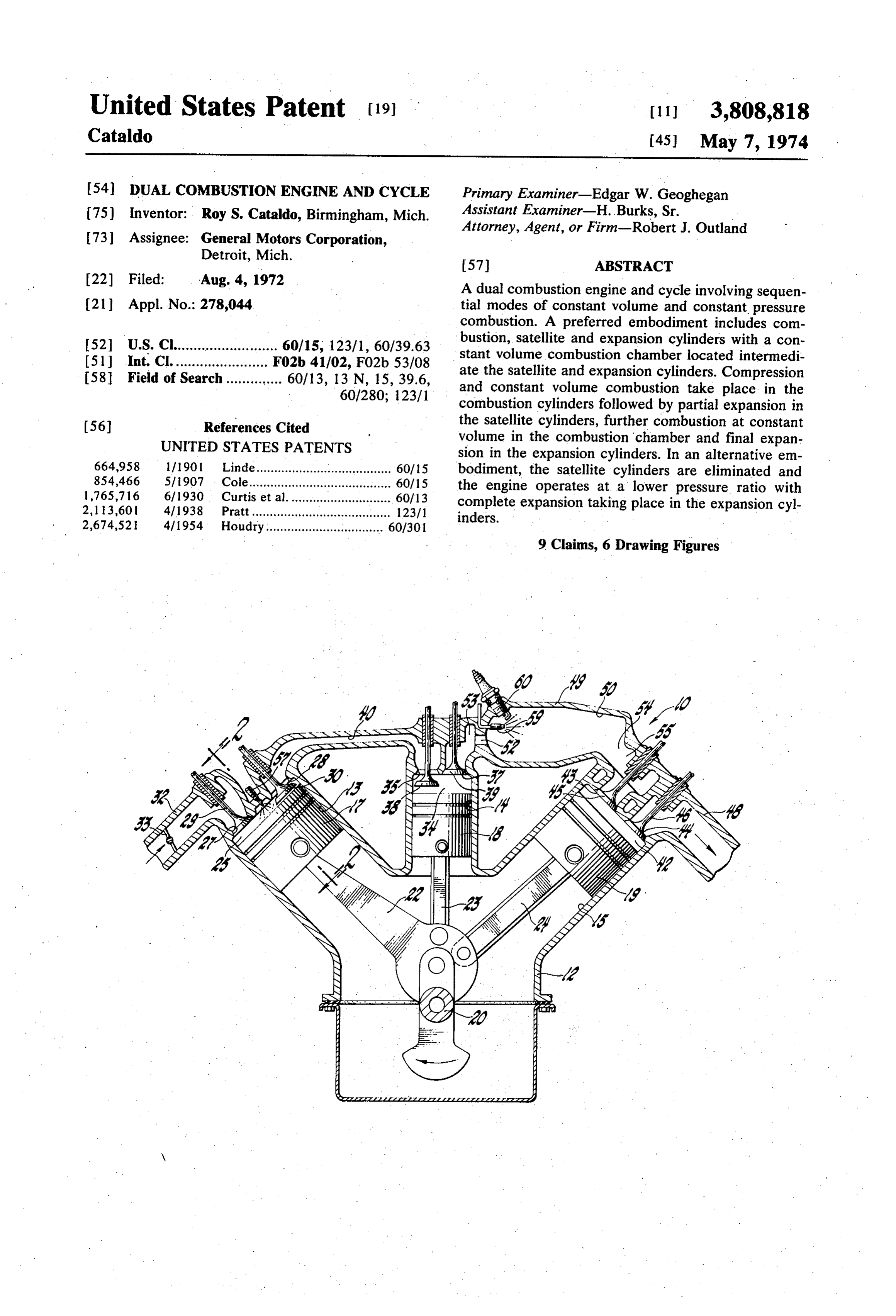
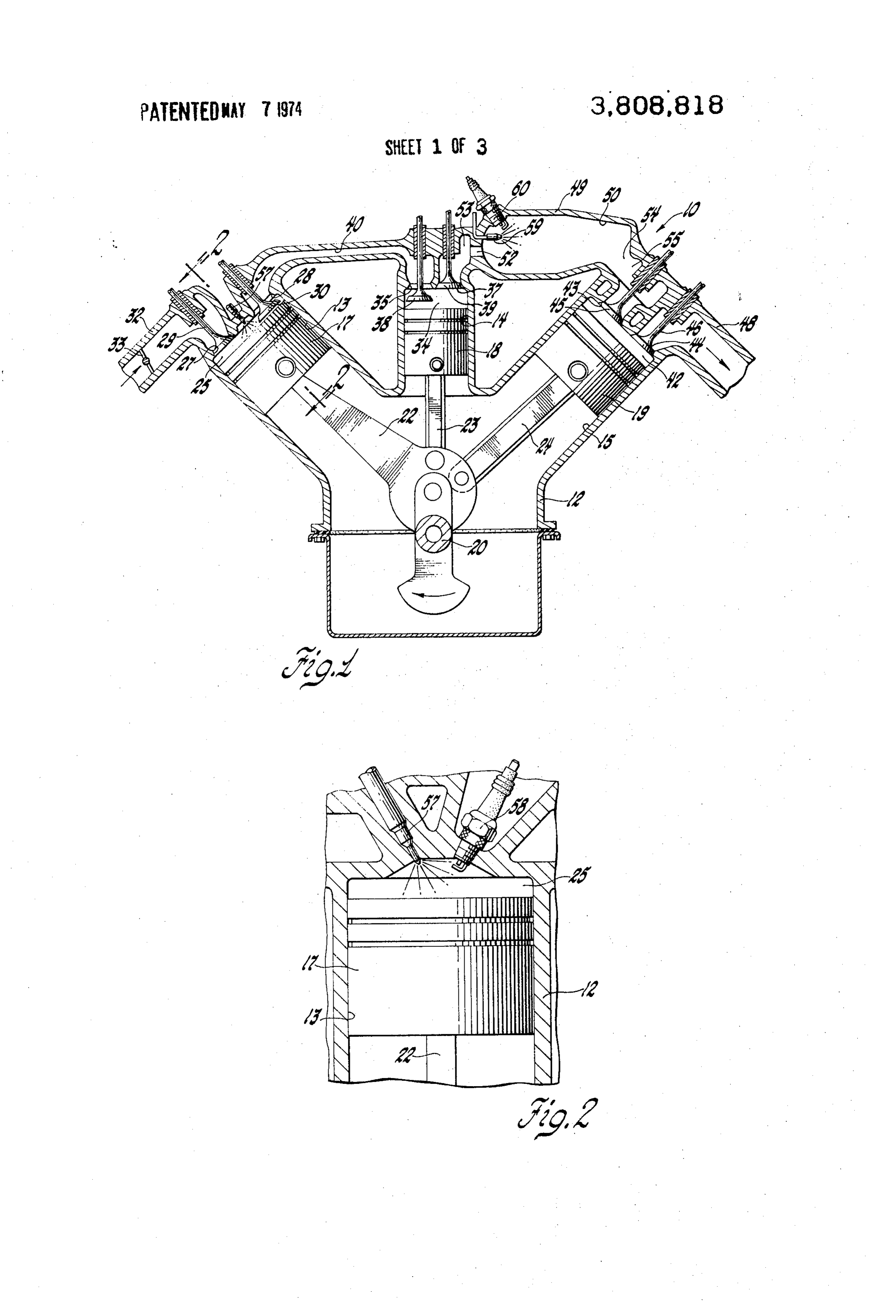
FIELD OF THE INVENTION Referring first to FIGS. 1 and 2 of the drawings, nu meral 10 generally indicates a dual combustion engine
This invention relates to combustion engines and, 5 formed more particularly, to engines having positive displace according to the invention. Engine 10 includes a cylinder ment means for compression and expansion of the cluding combustion block 12 having a plurality of cylinders, in working charge, combined with dual combustion pha and expansion cylinders cylinders 13, satellite cylinders 14 ses, including initial combustion at constant volume, 10 arranged in three banks, each 15. The various cylinders are followed by final combustion at constant pressure. made up of a plurality of the same type of cylinder and each preferably having
SUMMARY OF THE INVENTION at least three cylinders, only one of which is shown. The present invention provides an improvement in cable Cylinders 13, 14, 15 are each provided with recipro combustion engines which combines the constant vol 15 nectedpistons 17, 18, 19, respectively, which are con ume burning of the Otto cycle with the constant pres 20 by means ofofconnecting with one the throws of the engine crankshaft
sure burning of the Brayton cycle to yield a dual com tively. In this manner, reciprocation bustion cycle engine utilizing positive displacement a predetermined cycle relative to oneofanother the pistons on is pro means for compression and expansion of the working vided.
charge. The invention takes advantage of the improved 20 Combustion cylinders 13 and pistons 17 together de combustion control and emission characteristics possi fine variable volume working or combustion chambers ble in a fixed volume constant pressure burner while 25, which are provided with inlet and outlet ports 27, retaining in part the advantage of the higher efficiency 28 controlled by inlet and outlet valves 29, 30, respec of constant volume combustion for heating and com tively. Inlet port 27 connects through passage means 32 pressing the charge. 25 controlled by a throttle 33 with a source of air, not Numerous variations of engine physical arrange shown.
ments, components and cycle variations are possible Satellite cylinders 14 and their respective pistons 18 within the scope of the overall fuel combustion con together define working chambers 34 having inlet and cept. However, a preferred embodiment involves the outlet ports 35, 37, controlled by inlet and outlet valves use of interconnected piston-cylinder arrangements for 30 38, 39, respectively. Inlet ports 35 of the satellite cylin positive displacement, compression and expansion of ders connect through transfer passages 40 with the out the working charge. Additional satellite expansion cyl let ports 28 of their respective combustion cylinders. inders may be utilized to partially expand a charge fol Expansion cylinders 15 and their respective pistons lowing constant volume combustion, after which con 19 together define expansion chambers 42, having inlet stant pressure combustion and final expansion occur. 35 and outlet ports 43, 44 controlled by inlet and outlet Alternatively, the satellite cylinders may be deleted and valves 45, 46, respectively. Outlet ports 44 communi the engine arranged for a lower initial compression cate with an exhaust passage 48 which may be con ratio with constant volume combustion in the compres nected with suitable muffling and/or exhaust treatment sion and combustion cylinders, being directly followed 40 means, not shown.
by constant pressure combustion in the fixed volume lite cylinders 14the
Intermediate cylinder banks containing the satel and the expansion cylinders 15, there combustion chamber. is provided a walled enclosure 49 defining a fixed vol These and other features and advantages of the in ume combustion chamber 50. Combustion chamber 50 vention will be more clearly understood from the fol includes a plurality of inlet ports 52, which connect lowing description of certain preferred embodiments, 45 through transfer passage means 53 with the outlet ports chosen for purposes of illustration, taken together with 37 of the respective satellite cylinders. The combustion the accompanying drawings. chamber 50 has at the end opposite the inlet ports, a BRIEF DESCRIPTION OF THE DRAWINGS plurality of outlet ports 54 which connect through suit In the drawings: able transfer passages 55 with the inlet ports 43 of the 50 respective expansion cylinders 15.
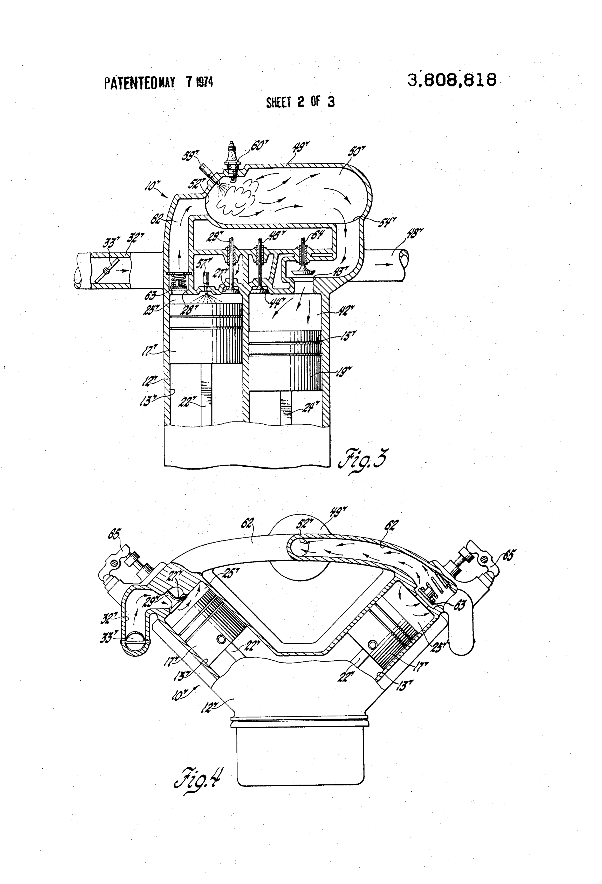
FIG. 1 is a diagrammatic cross sectional view illus Fuel supply means and ignition means are provided trating the arrangement of one embodiment of an en for both the combustion chambers of cylinders 13 and gine according to the invention; the fixed volume combustion chamber 50. These in FIG. 2 is a cross sectional view of a combustion cylin 55 clude injection nozzles 57 and spark plugs 58, located der of the engine of FIG. 1 taken in the plane generally in the walls of the respective combustion chambers 25 indicated by the line 2-2 of FIG. 1 and showing the lo and fuel injection nozzle 59 and spark plug 60 located cation of the fuel injection and ignition means; in the wall 49 of the fixed volume combustion chamber FIG. 3 is a longitudinal cross sectional view showing 50. In each case, the fuel injection nozzles and the diagrammatically the relations of elements of an alter spark plugs from the respective chambers are located native embodiment of engine, according to the inven 60 such that a relatively small fuel spray from the injection tion; nozzles will form a locally rich fuel mixture that may be FIG. 4 is a transverse cross sectional view showing ignited by the spark plug, regardless of the amount of other constructional aspects of the engine of FIG. 3; fuel present in the remaining portions of the combus and 65 tion chamber.
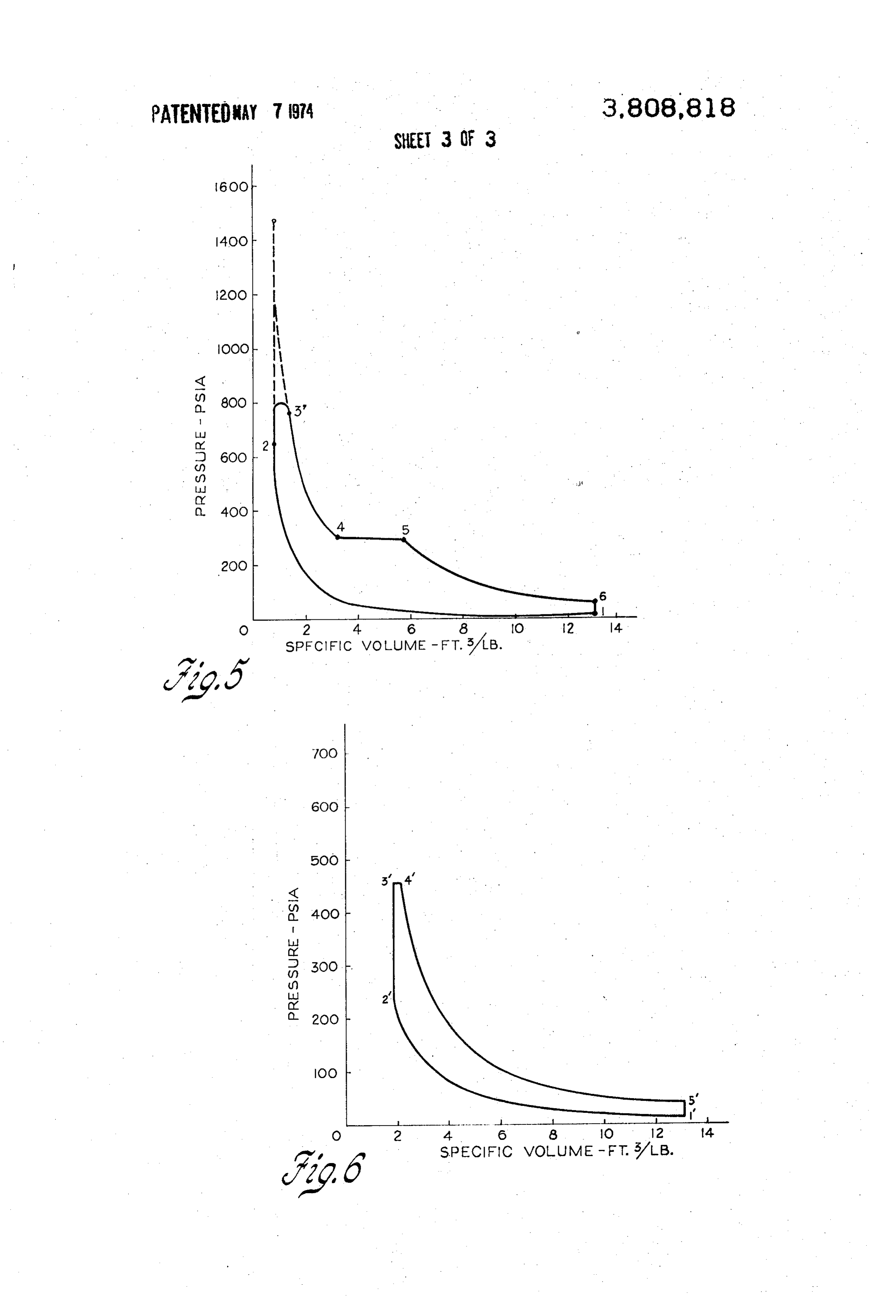
FIGS. 5 and 6 are graphical presentations of pres Although not shown, it should be understood that the sure-volume diagrams comparing the cycle differences engine further includes suitable means for operating of the embodiments disclosed in the drawings. the various fuel supply means and ignition means in
Page 6
timed relation with the movement of the engine pistons opened and the piston moves upwardly, forcing out the in order to carry out the intended operating cycle of the expanded combustion products. engine, as will be subsequently fully described. It should be noted that the partial expansion of the
OPERATION
charge in the satellite cylinders and the final expansion 5 of the gases in the expansion cylinders both result in the
In operation, the various pistons, inlet and exhaust development of useful work which is transmitted to the valves, and fuel injection and ignition means are oper engine crankshaft in conventional fashion, some of this ated in timed relation upon rotation of the crankshaft work being absorbed in the operation of the combus 20. Upon the downward motion of each piston 17, its tion pistons 17, as well as the other engine components. inlet valve 29 opens, permitting a charge of air to be 10 drawn into the combustion chamber 25 through the In FIG. 5 there is shown a pressure-volume diagram inlet passage means 32. Valve 29 then closes and piston which illustrates the operation of the above-described 17 moves upwardly, compressing the air charge until cycle of the embodiment of FIGS. 1 and 2. Line 1-2 the piston reaches a position near top dead center. A represents the compression of the charge in cylinders small charge of fuel is then injected into the combus 15 13. Line 2-3 represents theoretical adiabatic constant tion chamber 25, forming a combustible mixture which volume combustion in these cylinders with line 2 - 3' is ignited by the spark plug 58. The burning of the fuel indicating the curve as modified by heat losses. Line air mixture further compresses and heats the charge. 3'-4 represents the partial expansion of the charge in However, the amount of fuel injected is sufficient to satellite cylinders 14. Line 4-5 represents the constant combine with only a small part of the air in the charge 20 pressure combustion in chamber 50, while line 5-6 rep resents the final expansion of the gases in the expansion so that a mixture of excess air and combustion products cylinders.
is formed by the combustion in cylinder 25. Line 6-1, of course, represents the return to atmospheric
Following and/or during the combustion, which oc charge and intake pressure due to the exhausting of the curs in chamber 25 at approximately constant volume, 25 of a fresh air charge. the exhaust valve.30 is opened, allowing the heated and ALTERNATIVE EMBODIMENT compressed charge of air and combustion products to escape through a transfer passage 40, passing through In FIGS. 3 and 4, there is illustrated an alternative the then open inlet valve 38 into the relatively large embodiment erally of dual combustion engine, which is gen indicated by numeral 10'. While the arrangement clearance space forming the working chamber 34 of of the components in engine 10' varies in a number of the associated satellite cylinder 14. Valves 30 and 38 ways from the arrangement of similar components in then close and the gases in chamber 34 are partially ex the embodiment of FIGS. 1 and 2, the use and opera panded as the satellite piston 18 moves downwardly. It tion of the components present is sufficiently similar to will be noted that the satellite cylinders and their re those of the first embodiment that it is necessary to dis spective pistons are smaller in diameter than the asso 35 cuss only the differences in construction and operation ciated combustion cylinders and pistons in order to between the provide for this partial expansion of the charge. At the numerals havetwo embodiments. Accordingly, primed been utilized in FIGS. 3 and 4 to indi end of the downward stroke of piston 18, the outlet cate components corresponding in operation and func valve 39 is opened. The charge is exhausted from each tion to like elements of the embodiment of FIGS. 1 and satellite cylinder on the upward stroke of its respective 40 2.
pistons, passing through the respective transfer passage The construction of engine 10' differs from that pre 53 and port 52 into the fixed volume combustion cham viously described in that the two cylinder banks each ber 50. contain both a combustion cylinder 13' and an expan Preferably, the combustion chamber 50 will be sup sion cylinder 15'. It should also be noted that the satel plied by at least three satellite cylinders, each asso lite cylinders are completely eliminated and the longi
ciated with a combustion cylinder and the pistons of tudinally extending fixed volume combustion chamber these satellite and combustion cylinders will be sequen 50' communicates directly with the combustion cham tially timed so that the admission of air and combustion bers 25' of the combustion cylinders 13' through trans products into the combustion chamber 50 is more or fer passages 62, which are controlled by spring-biased less continuous. In the combustion chamber 50, addi 50 check valves 63. The compression ratio of the combus tional fuel is admitted to the working charge through tion cylinders is reduced in view of the absence of satel the fuel nozzle 59 and the mixture formed is ignited by lite cylinders. Another variation in design is that the spark plug 60 and burned at constant pressure, further inlet valves 64 of expansion cylinders 15' are arranged heating and expanding the charge. to open outwardly in the fashion of a steam engine. From the fixed volume combustion chamber 50, the 55 Rocker means 65 are illustrated for actuating the inlet gases then pass through the various expansion cylin and exhaust valves of the combustion and expansion ders, to which they are admitted by the opening of the cylinders, respectively.
respective inlet valves 45 when the pistons 19 are near The operation of the alternative embodiment is like their respective top dead center positions. The prod 60 that of the embodiment first described in many re ucts are then expanded by the downward motion of the spects. A charge of air is drawn into the combustion pistons 19 in the expansion cylinders, with the admis cylinders 13' and compressed, followed by the injec sion of gases being cut off by closing of the inlet valves tion of a small amount of fuel and burning of the charge at a suitable point in the expansion stroke, which may, at substantially constant volume conditions. This if desirable, be made adjustable in much the same man 65 causes further heating and compression, forcing the ner as the cutoff point of the steam engine inlet valve charge out through check valve 63 and into the fixed may be made variable. When each piston 19 reaches its volume combustion chamber 50', at which point addi downward position, the respective exhaust valve 46 is tional fuel is added and the mixture is ignited for burn
Page 7
S 6 ing at constant pressure. The remaining gases are then fuel mixture in a small portion of said compressed transferred into the expansion cylinders 15' and ex charge, panded in the manner previously described, with the first ignition means connected with said expansible resultant work output. chamber to ignite said air-fuel mixture for burning FIG. 6 shows a pressure-volume diagram illustrating at substantially constant volume within said expan the cycle of the alternative embodiment of FIGS. 3 and sible chamber to heat and further compress said 4. Line 1'-2' represents the compression of the charge charge, in cylinders 13'. Line 2'-3' represents constant volume fixed volume combustion chamber means connected with said first expansible chamber to receive the combustion in these cylinders. Line 3'-4" shows con O compressed stant pressure combustion in chamber 50'. Line 4'-5' and heated charge of air and combus illustrates expansion of the gases in the expansion cylin tion products therefrom, ders 15' and Line 5'-1' shows the return to atmo second fuel delivery means connected with said com spheric pressure through exhausting of the charge. bustion chamber to deliver additional fuel to said While the invention has been described by reference 15 charge so as to create a combustible air-fuel mix to certain preferred embodiments, it should be appar ture with the remaining air in said charge, ent that numerous changes could be made in the man second ignition means connected with said combus ner of utilizing the inventive concepts disclosed in the tion chamber to ignite the combustible mixture arrangement and construction of combustion engines. therein for burning at substantially constant pres sure, and
Accordingly, it is intended that the invention not be 20 second expansible chamber means connected with limited except by the language of the following claims. said combustion chamber to receive the combus I claim:
tion products therefrom and expand such products 1. A dual combustion engine comprising with a resultant output of useful work. first and second expansible chamber defining means 25 strokeIn dual 4. a combustion engine adapted to operate a two movable through successive steps of expansion and stant volumecombustion and cycle including separate con constant pressure combustion steps,
combustion chamber means defining a fixed volume first expansible chamber means adapted to receive combustion chamber connected with and interme and compress a charge of air, diate said expansible chambers, 30 first fuel delivery means connected with said expansi first and second fuel supply means connected to sup ble chamber to deliver a limited amount of fuel into ply fuel to said first expansible chamber and said said compressed air charge for combustion with a combustion chamber, respectively and small portion of said compressed charge at substan means cyclically inter-relating operation of said ex tially constant volume within said expansible cham pansible chamber and fuel supply means to receive 35 ber to heat and further compress said charge, and compress an air charge in said first expansible second expansible chamber means connected with chamber, to heat and further compress said charge said first expansible chamber to receive the com by combustion of a small quantity of fuel in said pressed and heated charge of air and combustion first expansible chamber, to transfer the com products therefrom, said second expansible cham pressed charge to the combustion chamber for the 40 ber being operative to partially expand said charge addition of further fuel and combustion with the with an output of useful work and to exhaust the remaining air and to expand the resulting products compressed and heated charge of air and combus in said second expansible chamber with a resulting tion products at a lower temperature and pressure work output, said inter-relating means causing than received, each of said expansible chamber means to operate 45 fixed volume combustion chamber means connected on a repetitive two-stroke cycle. with said second expansible chamber to receive 2. The engine of claim 1 and further comprising third therefrom the compressed and heated charge of air expansible chamber defining means connected inter and combustion products, mediate said first expansible chamber and said combus 50 second fuel delivery means connected with said com tion chamber, said third expansible chamber means bustion chamber to deliver additional fuel to said being connected with said inter-relating means and op charge so as to create a combustible air-fuel mix erable on a two-stroke cycle to receive the charges of ture with the remaining air in said charge, compressed air and combustion products during their ignition means connected with said combustion transfer from said first expansible chamber to said com 55 chamber to ignite the combustible mixture therein bustion chamber and to partially expand said charges for burning at substantially constant pressure and to obtain useful work, subsequently delivering each charge to said combustion chamber at a reduced pres third expansible chamber means connected with said sure for said further fuel addition and combustion. combustion chamber to receive the combustion 3. In a combustion engine adapted to operate on a 60 products therefrom and expand such products with two stroke dual combustion cycle including separate a resultant output of useful work. constant volume and constant pressure combustion 5. The method of burning fuel in a dual combustion steps, work producing cycle, said method comprising the first expansible chamber means adapted to receive steps of positive displacement compression of a charge of air,
first fuel delivery means connected with said expansi ble chamber to deliver a limited amount of fuel into admission and burning of a first small charge of fuel said air charge so as to create a combustible air in said air charge, said first fuel charge being suffi
Page 8
cient to combine with only a small portion of the gases on the expansion strokes of the respective oxygen in said air charge and said burning being pistons with a resultant output of work, and performed under conditions approximating con g. exhaust of the spent gases on the exhaust strokes stant volume combustion, of the respective pistons. subsequent admission and burning of a second 5 8. A combustion engine according to claim 7 and fur- . charge of fuel in the resulting mixture of air and ther comprising combustion products, said burning of said second a plurality of satellite cylinders with reciprocating fuel charge being performed under conditions ap pistons therein connected with said crankshaft and proximating constant pressure combustion, and defining with their respective cylinders variable positive displacement expansion of the resulting 10 volume working chambers, said working chambers products with a resultant work output. each having inlet and outlet passages controlled by 6. The method of claim 7 and comprising the addi valves, each of said satellite cylinders being con tional step of positive displacement partial expansion of nected intermediate an associated one of said com the mixture of air and combustion products resulting bustion cylinders and said fixed volume combus from the burning of said first small fuel charge, said 5 tion chamber, with said satellite cylinder inlet pas step of partial expansion resulting in an output of work sages each connecting with the outlet passage of and being performed before the admission and burning the associated combustion cylinder and the satel of said second fuel charge. lite cylinder outlet passages connecting with the 7. In a combustion engine adapted to operate on a fixed colume combustion chamber inlet means, two-stroke dual combustion cycle including separate 20 the pistons and valves of said satellite cylinders being constant volume and constant pressure combustion arranged with respect to the other engine compo steps, nents to cause gases being transferred in step “d' an engine block including first and second angularly from the various combustion cylinders to the fixed disposed cylinder banks and mounting a crank volume combustion chamber to be partially ex shaft, 25 panded in the respective satellite cylinders on the a plurality of cylinders in each of said banks, each expansion strokes of the respective pistons with a cylinder having a piston reciprocably disposed resultant work output.
therein and defining an expansible chamber there 9. In a combustion engine adapted to operate on a with, said pistons being connected with said crank two-stroke dual combustion cycle including separate shaft, each cylinder having inlet and outlet pas 30 constant volume and constant pressure combustion sages and valves controlling said passages, steps, the cylinders in said first bank comprising combus an engine block including a plurality of angularly dis tion cylinders, having their inlet passages con posed cylinder banks and mounting a crankshaft, nected with a source of air and being provided with 35 first and second cylinders in each of said banks, each fuel supply means and ignition means, cylinder having a piston reciprocably disposed the cylinders in said second bank comprising expan therein and defining an expansible chamber there sion cylinders, and with, said pistons being connected with said crank means defining a fixed volume combustion chamber shaft, and each cylinder having inlet and outlet pas having inlet and outlet passage means, fuel supply 40 sages and valves controlling said passages, means and ignition means, said inlet passage means said first cylinders of each bank comprising combus being connected with the outlet passages of said tion cylinders having their inlet passages connected combustion cylinders to receive mixed air and with a source of air and being provided with fuel. combustion products therefrom and said outlet supply means and ignition means, passage means being connected with the inlet pas 45 said second cylinders of each bank comprising ex sages of said expansion cylinders to deliver com pansion cylinders, and bustion products thereto, means defining a fixed volume combustion chamber said pistons, valves, fuel supply means and ignition having inlet and outlet passage means, fuel supply means being operably related through said crank means and ignition means, said inlet passage means shaft to cause said engine to perform an operating SO being connected with the outlet passages of said cycle including the steps of: combustion cylinders to receive mixed air and a. air admission to the combustion cylinders during combustion products therefrom and said outlet the intake strokes of their respective pistons, passage means being connected with the inlet pas b. compression of air in the combustion cylinders sages of said expansion cylinders to deliver com during the compression strokes of their respec 55 bustion products thereto, tive pistons, said pistons, valves, fuel supply means and ignition c. admission of small charges of fuel, ignition and means being operably related through said crank burning in the combustion cylinders in a near shaft to cause said engine to perform an operating constant volume process which further heats and cycle including the steps of: . compresses the remaining air and gas, 60 a. air admission to the combustion cylinders during d. transfer of the compressed and heated gases to the intake strokes of their respective pistons, the fixed volume combustion chamber, b. compression of air in the combustion cylinders e. admission of additional fuel, ignition and burning during the compression strokes of their respec thereof with the remaining air in the fixed vol tive pistons, ume chamber in a near constant pressure process 65 c. admission of small charges of fuel, ignition and which further heats the gases, burning in the combustion cylinders in a near f. transfer of the compressed and heated gases to constant volume process which further heats and the expansion cylinders and expansion of the compresses the remaining air and gas,
Page 9
d. transfer of the compressed and heated gases to the expansion cylinders and expansion of the the fixed volume combustion chamber, gases on the expansion strokes of the respective e. admission of additional fuel, ignition and burning pistons with a resultant output of work, and thereof with the remaining air in the fixed vol g. exhaust of the- spent gases on the exhaust strokes ume chamber in a near constant pressure process 5 - - which further heats the gases, of the respective pistons. f. transfer of the compressed and heated gases to k k k xk sk
Provenance
- Collection
- Cited prior art
- Original PDF
- patentimages.storage.googleapis.com →
- Filed
- 1972-08-04
- Pages
- 9
- Method
- pdftotext (the PDF's own text layer) + pdftoppm 300dpi page scans
- Source
- Google Patents bibliographic record
- Granted
- 1974-05-07
- Inventors
- R Cataldo; General Motors Corp
- Transcribed from
- patentimages.storage.googleapis.com →