patent · US3958540
Staged internal combustion engine with interstage temperature control
25 May 1976
Page 1 — bibliographic record
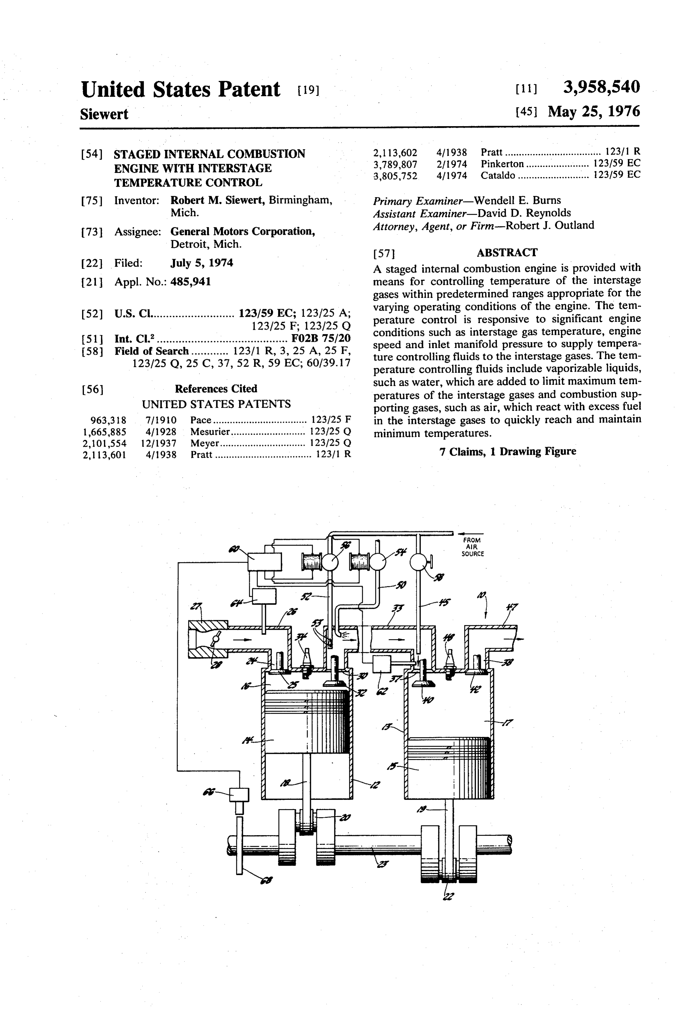
United States Patent (19) [11] 3,958,540 Siewert (45) May 25, 1976 54). STAGED INTERNAL COMBUSTION 2,113,602 4/1938 Pratt................................... 12311 R ENGINE WITH INTERSTAGE 3,789,807 2/1974 Pinkerton.... ... 123159 EC TEMPERATURE CONTROL 3,805,752 4/1974 Cataldo.......................... 123/59 EC I75 Inventor: Robert M. Siewert, Birmingham, Primary Examiner-Wendell E. Burns Mich. Assistant Examiner-David D. Reynolds 73 Assignee: General Motors Corporation, Attorney, Agent, or Firm-Robert J. Outland Detroit, Mich. 57 ABSTRACT 22 Filed: July 5, 1974 A staged internal combustion engine is provided with 21 Appl. No.: 485,941 means for controlling temperature of the interstage gases within predetermined ranges appropriate for the 52 U.S. Cl........................... 123/59 EC: 123/25 A; varying operating conditions of the engine. The tem
perature control is responsive to significant engine 51 Int. Cl’.......................................... F02B 75/20 conditions such as interstage gas temperature, engine
speed and inlet manifold pressure to supply tempera 123/25 O, 2.5 C, 37, 52 R, 59 EC; 60/39.17 ture controlling fluids to the interstage gases. The tem perature controlling fluids include vaporizable liquids,
References Cited such as water, which are added to limit maximum tem 56 peratures of the interstage gases and combustion sup UNITED STATES PATENTS porting gases, such as air, which react with excess fuel 963,318 7/1910 Pace.................................. 123,125 F in the interstage gases to quickly reach and maintain 1,665,885 4, 1928 Mesurier......... ... i. 23/25 O minimum temperatures.
2,101,554 12/1937 Meyer................ ... 123/25 O 2,113,601 4/1938 Pratt................................... 12311 R 7 Claims, 1 Drawing Figure
waaaaaaaaaa.
Page 2
Drawing sheet — no readable text.
Page 3
nate the need for interstage temperature control; since,
STAGED INTERNAL COMBUSTION ENGINE WITH if the temperature of gas admitted to the second stage INTERSTAGE TEMPERATURE CONTROL is too low, misfiring may occur; while if the tempera
FIELD OF THE INVENTION
ture is too high, pre-ignition will occur, resulting in overadvanced timing and inefficient operation. In addi
This invention relates to internal combustion engines tion, some degree of interstage temperature control is of the staged combustion type and, more particularly, necessary to prevent inefficient thermal reaction in the to means for controlling interstage gas temperatures in interstage manifold.
such engines. SUMMARY OF THE INVENTION
BACKGROUND OF THE INVENTION The present invention provides means for controlling It is known in the art to arrange an internal combus interstage gas temperatures in staged internal combus tion engine to perform the combustion of a fresh tion engines, in order to maintain such temperatures charge of fuel in two separate sequential working cy within desired ranges. More specifically, the invention cles having separate stages of combustion and each 15 provides control of interstage gas temperatures by the yielding an output of work to the engine output shaft. addition of temperature controlling fluids to the inter The general method of operation of such engines, stage manifold, preferably near its connection with the which I refer to as staged combustion engines, involves first stage exhaust port, whereby temperature control the admission of a rich air-fuel charge to an engine ling fluids will be mixed with the interstage gases combustion chamber wherein it is passed through a 20 shortly after their expulsion from the first stage com first stage working cycle including compression, com bustion chamber.
bustion and expansion steps. This cycle results in the One feature of a cooling system according to the delivery of power to the engine output shaft and leaves invention is that it provides means for cooling the inter a residual charge of combustion products and incom stage gases by spraying a vaporizable liquid, preferably pletely burned combustibles. To this charge, air is 25 water, into the interstage manifold, whereby the inter added to form a second and preferably somewhat lean stage gases are cooled by vaporization of the liquid. combustible mixture heavily diluted with burned gases. Another feature of a cooling system according to the This mixture is passed through a second stage cycle of invention is that means are provided for heating the compression, combustion and expansion, again yield interstage gases by directing a combustion supporting ing work to the engine output shaft. 30 fluid, such as air, into the interstage manifold for mix Such a process is capable of being performed sequen ture and reaction with combustibles in the hot gases tially in the same engine combustion chamber. How leaving the first stage so as to increase interstage gas ever, it is presently believed preferable to utilize sepa temperatures.
rate combustion chambers of the same engine for per 35 Another feature of the invention is that control formance of the two combustion cycles and to transfer means are provided which are operable in response to the products resulting from the first stage combustion engine conditions such as interstage gas temperature, cycle to the second stage combustion chamber through engine speed and engine load to control the admission a connecting interstage passage, conduit or manifold in of temperature controlling fluids into the interstage which the necessary secondary combustion air is 40 manifold.
added. These and other features of the invention will be Various forms of staged combustion engines have more fully understood from the following description been proposed. Among these are the arrangements of a preferred embodiment, taken together with the disclosed in U.S. Pat. Nos. 2,113,601 and 2,113,602, accompanying drawing.
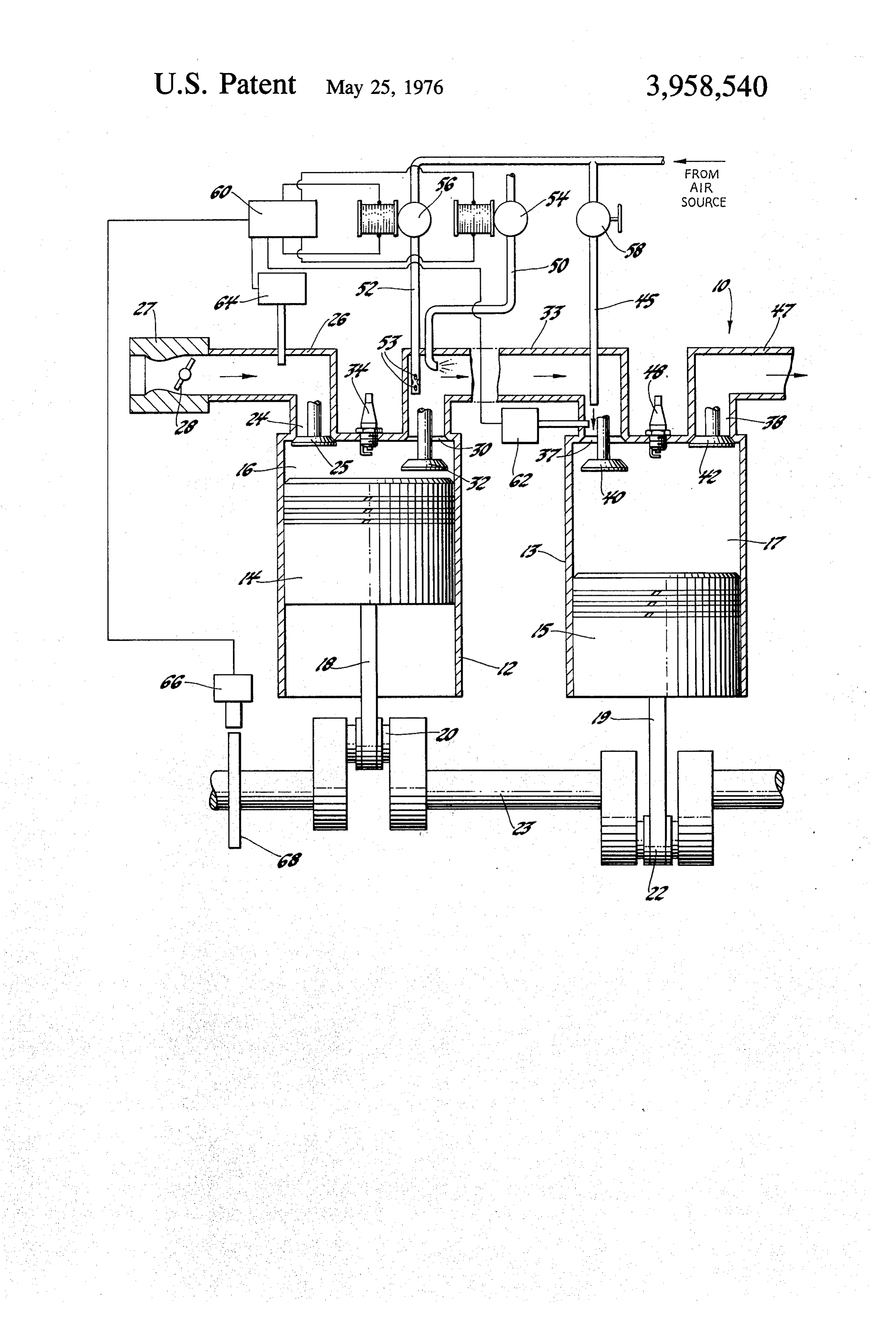
both granted April 12, 1938 to N. P. Pratt. Additional BRIEF DESCRIPTION OF THE DRAWING forms and methods of operation of such engines are 45 disclosed in my copending U.S. patent application Ser. The single drawing FIGURE is a diagrammatic view No. 282,390, filed Aug. 21, 1972. of a staged combustion engine having interstage gas In experimental work with staged combustion temperature control means in accordance with the engines operating with gasoline fule-air mixtures, I 50 invention.
have preferred to utilize conventional spark ignition for DESCRIPTION OF THE ILLUSTRATED initiating first stage combustion. However, I have found EMBODIMENT that satisfactory engine operation may be obtained under properly controlled conditions utilizing either In the drawing, numeral 10 generally indicates an compression ignition or conventional spark ignition for 55 internal combustion engine of the staged combustion initiation of second stage combustion. type and having a pair of cylinders 12, 13 containing Both methods of operation have been shown to re reciprocating pistons 14, 15, respectively, and defining quire some degree of temperature control of the inter therewith variable volume working and combustion stage gases in order to maintain engine operation and chambers 16, 17, respectively. Pistons 14, 15 are re efficiency under the varying loads and speeds required spectively connected by connecting rods 18, 19 to the of automotive type engines. For example, my copend 60 oppositely eccentric throws 20, 22 of a crankshaft 23. ing U.S. application Ser. No. 282,390 discloses that Cylinder 12 includes an inlet port 24, controlled by interstage gas temperatures must be controlled within an inlet poppet valve 25 and connecting through an predetermined ranges which are functions of other inlet manifold or conduit 26 with a source of air and engine variables such as engine speed, load and second 65 fuel mixture, such as a carburetor 27 having a throttle stage compression ratio, in order to realize efficient 28. Cylinder 12 also includes an exhaust or outlet port timing of second stage ignition when compression or 30 controlled by an exhaust poppet valve 32 and con auto-ignition is utilized. The use of spark ignition in the necting with an interstage manifold or conduit 33. A second stage reduces the criticality but does not elimi spark plug 34 is also provided in the cylinder 12 to
Page 4
ignite combustible fuel mixtures in the combustion interstage temperatures below a predetermined level to chamber 16. avoid undesired reaction of combustibles in the inter Cylinder 13 includes inlet and exhaust ports 37, 38 stage gases with the air added in the interstage mani controlled respectively by an inlet poppet valve 40 and fold.
an exhaust poppet valve 42. Inlet port 37 connects In accordance with the present invention, control of through the interstage manifold 33 with the combus interstage gas temperatures may be accomplished by tion chamber 16 of cylinder 14. An air admission pipe the novel means and methods described herein. To 45 extends into the interstage manifold 33 at a point accomplish this, engine 10 is provided with a water adjacent the second stage inlet port 37 to provide sec inlet pipe 50 and an air inlet pipe 52, each extending ondary combustion air for mixture with the interstage 1 O into the interior of the interstage manifold 33 at the end gases supplied to the second stage combustion chamber adjacent the first stage exhaust port 30. The outlet end 17. An exhaust conduit 47 connects with the exhaust of pipe 52 may be perforated as at 53 to better distrib port 38 to carry away the second stage exhaust gases. A ute fluid supplied thereby within the manifold 33. spark plug 48 is provided in cylinder 13 to ignite com Water pipe 50 is connected with a suitable source of bustible fuel mixtures in the combustion chamber 17. pressure water supply, such as an engine operated The operation of the engine portions so far disclosed water pump and storage tank (not shown), and is pro is as follows: vided with a solenoid operated valve 54 to control Upon rotation of the crankshaft, pistons 14 and 15 water flow through the pipe 50 to the interstage mani reciprocate in their respective cylinders in timed rela fold. Air pipe 52 is connected with a suitable source of tion with the valves so as to cause the combustion pressurized air, such as an engine operated air pump chambers 16, 17 to cyclically perform four-stroke cy (not shown), and is provided with a solenoid actuated cles including the steps of intake, compression, expan valve 56 for controlling air flow through pipe 52 to the sion and exhaust. Carburetor 27 supplies air-fuel mix interstage manifold. As shown in the drawing, a com tures, preferably rich in fuel, to the inlet manifold 26 mon source of air may be provided for both pipes 45 which are admitted in amounts controlled by the throt 25 and 52, and pipe 45 may be provided with a valve 58 tle 28 to the combustion chambers 16 on the intake operated manually or by suitable automatic control stroke of piston 14. Here the charges are compressed, means in order to control the relative amounts of sec ignited by the spark plug 34, burned and expanded, ondary air delivered through the pipes 45 and 52. delivering power to the crankshaft. The remaining While it would be possible under some conditions to gases consisting of combustion products and residual 30 manually actuate the water and air temperature control combustibles, for which there was insufficient air to valves 54,56, it is preferable to provide suitable control burn in the first stage, are exhausted on the exhaust means to actuate the valves in response to predeter stroke of piston 14 into the interstage manifold 33. mined engine operating conditions. Engine 10 is pro Here secondary air is added through air admission pipe vided with such a system which includes control actuat 45 which mixes with the first stage exhaust gases to 35 ing means 60, such as suitable electronic circuitry, for form a heavily diluted and preferably somewhat lean actuating the valves in response to predetermined sig combustible mixture, that is admitted to the second nals from individual sensors indicating the various per stage combustion chamber 17 on the intake stroke of tinent engine conditions. Examples of electronic cir piston 15. This charge is then compressed, ignited by cuitry suitable for this purpose are known in the prior the spark plug 48, burned and expanded in chamber 40 art and are shown, for instance, by the comparator 17, with the resultant delivery of power to the crank circuit 21 of U.S. Pat. No. 3,767,972 Noddings et al. shaft. Subsequently, valve 42 is opened and the burned and the comparison circuit 14 of U.S. Pat. No. gases are exhausted through exhaust conduit 47. 3,580,355 Kitano et al. Both references disclose means As disclosed in my previously mentioned application for comparing three separate input signals and re Ser. No. 282,390, the engine may also be operated 45 sponding thereto in predetermined manner by actuat utilizing compression-ignition of charges in the second ing either of two oppositely acting output devices or stage combustion chamber 17. Also if desired, both actuating neither, thus maintaining the status quo. The spark and compression-ignition could be utilized in the sensors for use with this circuitry include a temperature second stage cylinder under varying operating circum sensor 62 mounted to sense the temperature of the stances. If compression-ignition is used exclusively, the 50 interstage gases adjacent the second stage inlet port 37, spark plug 48 could be dispensed with. In addition, the a pressure sensor 64 mounted to sense the inlet mani second stage cylinder could be provided with means, fold pressure 26 which indicates the load on the engine, such as a movable piston, for varying the compression and a speed sensor 66 in the form of an induction coil ratio of the second stage combustion chamber in order 55 mounted adjacent toothed wheel 68 on the engine to assist in controlling the timing of ignition when com crankshaft to act as an indication of the engine speed. pression-ignition is used. The sensors 62, 64, 66 feed information on the various Further in accordance with my previously mentioned engine operating conditions of significance to the con application, suitable means, such as a heat exchanger, trol actuating means 60 which is arranged to operate could be provided in the interstage manifold 33 to the valves to supply either water or air as necessary to control the temperature of the interstage gases in the 60 the interstage manifold in order to control gas tempera manner required for proper operation of the engine. In tures within the predetermined ranges. general, such control involves maintaining the temper For example, when the engine is started after an ature of the interstage gases delivered to the second extended shutdown, the sensor 62 will indicate that the stage cylinder within predetermined temperature interstage gas temperature is below the desired range, ranges suitable for various engine operating conditions 65 whereby the control actuating means will open the so that misfiring due to excessively cold temperatures valve 56, permitting air to flow through the pipe 52 into and pre-ignition due to excessively high temperatures the interstage manifold adjacent the first stage exhaust are both avoided. In addition, it is desirable to maintain port 30. This air will mix with the hot exhaust gases
Page 5
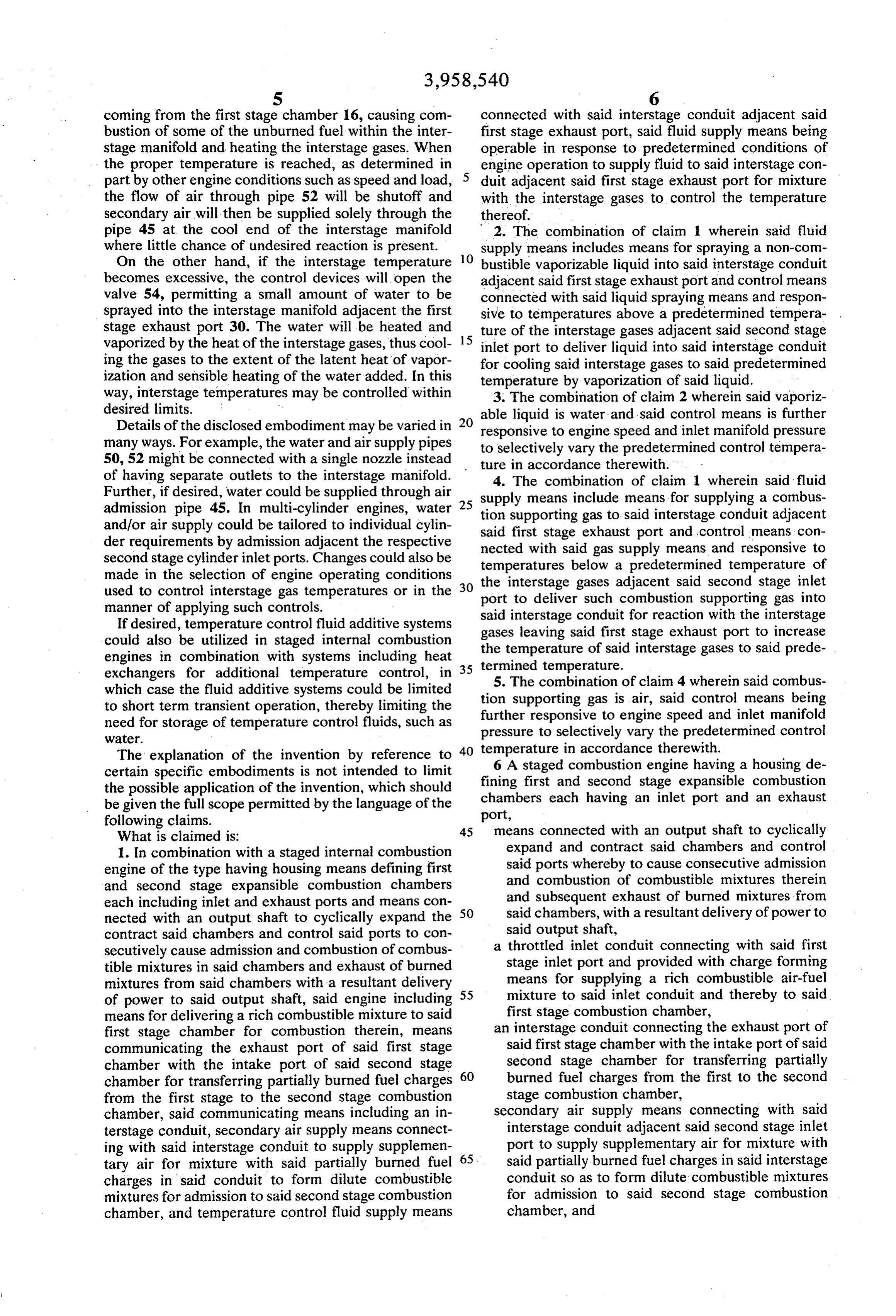
coming from the first stage chamber 16, causing com connected with said interstage conduit adjacent said bustion of some of the unburned fuel within the inter first stage exhaust port, said fluid supply means being stage manifold and heating the interstage gases. When operable in response to predetermined conditions of the proper temperature is reached, as determined in engine operation to supply fluid to said interstage con part by other engine conditions such as speed and load, duit adjacent said first stage exhaust port for mixture the flow of air through pipe 52 will be shutoff and with the interstage gases to control the temperature secondary air will then be supplied solely through the thereof.
pipe 45 at the cool end of the interstage manifold 2. The combination of claim 1 wherein said fluid where little chance of undesired reaction is present. O supply means includes means for spraying a non-com On the other hand, if the interstage temperature bustible vaporizable liquid into said interstage conduit becomes excessive, the control devices will open the adjacent said first stage exhaust port and control means valve 54, permitting a small amount of water to be connected with said liquid spraying means and respon sprayed into the interstage manifold adjacent the first sive to temperatures above a predetermined tempera stage exhaust port 30. The water will be heated and 15 ture of the interstage gases adjacent said second stage vaporized by the heat of the interstage gases, thus cool inlet port to deliver liquid into said interstage conduit ing the gases to the extent of the latent heat of vapor for cooling said interstage gases to said predetermined ization and sensible heating of the water added. In this temperature by vaporization of said liquid. way, interstage temperatures may be controlled within 3. The combination of claim 2 wherein said vaporiz desired limits. able liquid is water and said control means is further Details of the disclosed embodiment may be varied in responsive to engine speed and inlet manifold pressure many ways. For example, the water and air supply pipes to selectively vary the predetermined control tempera 50, 52 might be connected with a single nozzle instead ture in accordance therewith.
of having separate outlets to the interstage manifold. 4. The combination of claim 1 wherein said fluid Further, if desired, water could be supplied through air 25 supply means include means for supplying a combus admission pipe 45. In multi-cylinder engines, water tion supporting gas to said interstage conduit adjacent and/or air supply could be tailored to individual cylin said first stage exhaust port and control means con der requirements by admission adjacent the respective nected with said gas supply means and responsive to second stage cylinder inlet ports. Changes could also be temperatures below a predetermined temperature of made in the selection of engine operating conditions the interstage gases adjacent said second stage inlet used to control interstage gas temperatures or in the 30 port to deliver such combustion supporting gas into manner of applying such controls.
If desired, temperature control fluid additive systems said gases interstage conduit for reaction with the interstage leaving said first stage exhaust port to increase could also be utilized in staged internal combustion the temperature of said interstage gases to said prede engines in combination with systems including heat 35 termined temperature.
exchangers for additional temperature control, in 5. The combination of claim 4 wherein said combus which case the fluid additive systems could be limited tion supporting gas is air, said control means being to short term transient operation, thereby limiting the further need for storage of temperature control fluids, such as pressureresponsive to engine speed and inlet manifold to selectively vary the predetermined control
Water.
The explanation of the invention by reference to 40 temperature 6 A staged in accordance therewith.
combustion engine having a housing de certain specific embodiments is not intended to limit fining first and second stage expansible combustion the possible application of the invention, which should chambers each having an inlet port and an exhaust be given the full scope permitted by the language of the port, following claims. 45 means connected with an output shaft to cyclically What is claimed is:
1. In combination with a staged internal combustion expand and contract said chambers and control engine of the type having housing means defining first said ports whereby to cause consecutive admission and second stage expansible combustion chambers and combustion of combustible mixtures therein each including inlet and exhaust ports and means con 50 said and subsequent exhaust of burned mixtures from nected with an output shaft to cyclically expand the chambers, with a resultant delivery of power to contract said chambers and control said ports to con said output shaft, secutively cause admission and combustion of combus a throttled inlet conduit connecting with said first tible mixtures in said chambers and exhaust of burned stage inlet port and provided with charge forming mixtures from said chambers with a resultant delivery 55 means for supplying a rich combustible air-fuel of power to said output shaft, said engine including mixture to said inlet conduit and thereby to said means for delivering a rich combustible mixture to said first stage combustion chamber, first stage chamber for combustion therein, means an interstage conduit connecting the exhaust port of communicating the exhaust port of said first stage said first stage chamber with the intake port of said chamber with the intake port of said second stage 60 second stage chamber for transferring partially chamber for transferring partially burned fuel charges burned fuel charges from the first to the second from the first stage to the second stage combustion stage combustion chamber, chamber, said communicating means including an in secondary air supply means connecting with said terstage conduit, secondary air supply means connect interstage conduit adjacent said second stage inlet ing with said interstage conduit to supply supplemen 65 port to supply supplementary air for mixture with tary air for mixture with said partially burned fuel said partially burned fuel charges in said interstage charges in said conduit to form dilute combustible conduit so as to form dilute combustible mixtures mixtures for admission to said second stage combustion for admission to said second stage combustion chamber, and temperature control fluid supply means chamber, and
Page 6
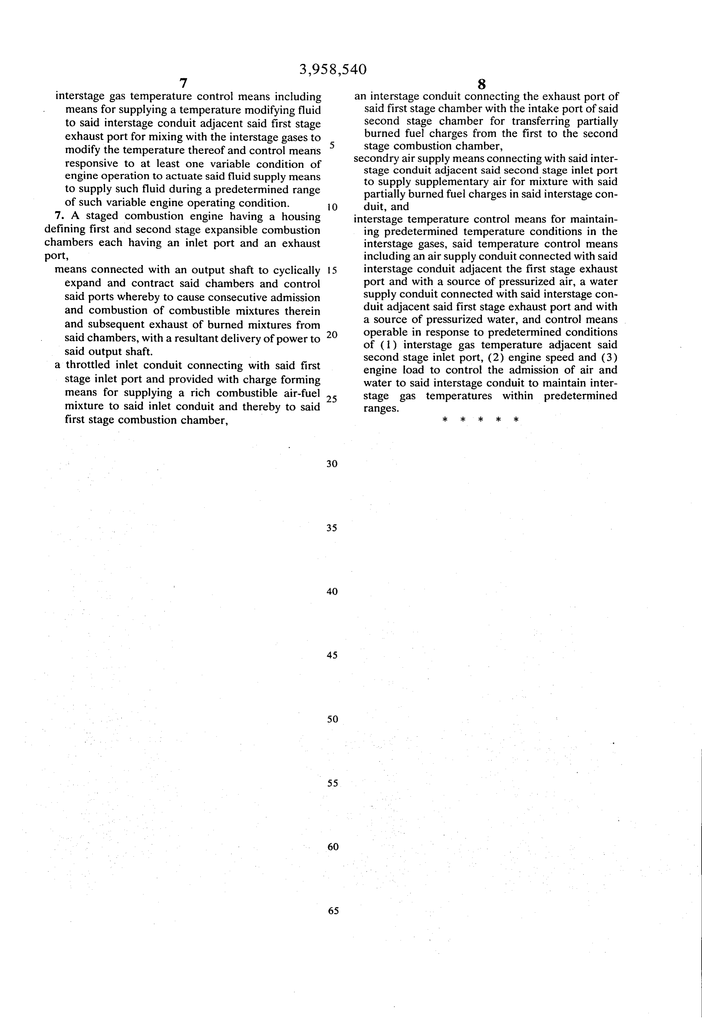
interstage gas temperature control means including an interstage conduit connecting the exhaust port of means for supplying a temperature modifying fluid said first stage chamber with the intake port of said to said interstage conduit adjacent said first stage second stage chamber for transferring partially exhaust port for mixing with the interstage gases to burned fuel charges from the first to the second modify the temperature thereof and control means 5 g Ebi chamber, ti ith said int responsive to at least one variable condition of seconary air supply stage conduit meanssaid adjacent connecting with said second stage inletinter port engine operation to actuate said fluid supply means to supply supplementary air for mixture with said to supply such fluid during a predetermined range partially burned fuel charges in said interstage con of such variable engine operating condition. 10 duit, and 7. A staged combustion engine having a housing interstage temperature control means for maintain defining first and second stage expansible combustion ing predetermined temperature conditions in the chambers each having an inlet port and an exhaust interstage gases, said temperature control means port, including an air supply conduit connected with said means connected with an output shaft to cyclically 15 interstage conduit adjacent the first stage exhaust expand and contract said chambers and control port and with a source of pressurized air, a water said ports whereby to cause consecutive admission supply conduit connected with said interstage con and combustion of combustible mixtures therein duit p said firE. that E. y with and subsequent exhaust of burned mixtures from a source of pressurized water, and control means said chambers, with a resultant delivery of power to 20 operable in response to predetermined conditions id output h ft y or power to of (1) interstage gas temperature adjacent said said output shatt. second stage inlet port, (2) engine speed and (3) a throttled inlet conduit connecting with said first engine load to control the admission of air and stage inlet port and provided with charge forming water to said interstage conduit to maintain inter means for supplying a rich combustible air-fuel 25 stage gas temperatures within predetermined mixture to said inlet conduit and thereby to said ranges.
first stage combustion chamber, ck k k is k
Page 7
UNITED STATES PATENT AND TRADEMARK OFFICE
CERTIFICATE OF CORRECTION
INVENTOR(S) : Robert M. Siewert It is Certified that error appears in the above-identified patent and that said Letters Patent are hereby corrected as shown below:
Column 1 line 49, "fulle-air" should read --fuel-air-- column 5, line 50, "the" should read --and--. Signed and Sealed this
Fourteenth Day of September 1976
RUTH C. MASON
C. MARSHALL DANN
Commissioner of Patents and Trademarks
Provenance
- Collection
- Cited prior art
- Original PDF
- patentimages.storage.googleapis.com →
- Filed
- 1974-07-05
- Pages
- 7
- Method
- pdftotext (the PDF's own text layer) + pdftoppm 300dpi page scans
- Source
- Google Patents bibliographic record
- Granted
- 1976-05-25
- Inventors
- Robert M. Siewert; General Motors Corp
- Transcribed from
- patentimages.storage.googleapis.com →