patent · US4198940
Split operation type multi-cylinder internal combustion engine
22 April 1980
Page 1 — bibliographic record
United States Patent (19) (11) 4,198,940 Ishida 45 Apr. 22, 1980 54). SPLIT OPERATION TYPE 57 ABSTRACT MULTI-CYLNDER INTERNAL Disclosed is a split operation type internal combustion COMBUSTON ENGINE engine having a plurality of cylinders which are divided 75 Inventor: Yasuhiko Ishida, Mishima, Japan into a first cylindergroup and a second cylindergroup. 73 Assignee: Toyota Jidosha Kogyo Kabushiki The cylinders of the first cylinder group are connected Kaisha, Toyota, Japan to a first common intake manifold equipped with a first carburetor, and the cylinders of the second cylinder 21 Appl. No.: 954,847 group are connected to a second common intake mani 22 Filed: Oct. 26, 1978 fold equipped with a second carburetor. The second intake manifold is connected to the exhaust manifold via 30 Foreign Application Priority Data a bypass passage, and an exhaust valve is arranged in the Jul. 6, 1978 (JP) Japan .................................. 53-81.421 bypass passage. A first gear actuated by the accelerator pedal is operatively connected to the first throttle valve 51 Int. C.? ..................... Fo2M 25/06; F02M 13/04; of the first carburetor and intermittently engaged with a F02D 9/00 second gear connected to the second throttle valve of 52 U.S. C. ............................. 123/119 A; 123/198 F the second carburetor. The firing operation is always 58 Field of Search ........................ 123/19 A, 198 F carried out in the first cylindergroup. When the level of 56 References Cited the vacuum produced in the first intake manifold is
valve remains closed, and the exhaust valve remains 3,776,207 12/1973 Simko .............................. 123/19 A fully opened. At this time the exhaust gas is fed into the 3,779,013 12/1973 Faber et al. ..................... 123/19 A second cylinder group. When the level of the vacuum 4,019,479 4/1977 Garabedian ...................... 123/198F 4,024,708 5A1977 Takemoto ........................ 123/19 A produced in the first intake manifold is reduced below 4,041,910 8/1977 Houseman ....................... 123/19 A the predetermined level, the first gear comes into en 4,068,637 lal978 Takamiya ........................ 123/19 A gagement with the second gear for opening the second 4,106,471 3/1978 Narajima et al. ... 123/98 F throttle valve and, at the same time, the exhaust valve is 4, 13,095 i2/1978 Ouchi................. ... 123/19 A closed so that the firing operation is started in the sec 4,143,635 3/1979 Iizuka et al. ..................... 123/19 A ond cylinder group.
Primary Examiner-Wendell E. Burns
Attorney, Agent, or Firm-Kenyon & Kenyon 1 13 Claims, 7 Drawing Figures
Page 2
Drawing sheet — no readable text.
Page 3
Drawing sheet — no readable text.
Page 4
Drawing sheet — no readable text.
Page 5
Drawing sheet — no readable text.
Page 6
under a light load, since air is fed into the cylinders of
SPLT OPERATION TYPE MULTI-CYLNDER the second cylindergroup from the bypass passage and INTERNAL COMBUSTION ENGINE then is discharged into the exhaust passage of the en gine, the temperature of the exhaust gas in the exhaust
DESCRIPTION OF THE INVENTION 5 passage is extremely reduced. As a result of this, there
The present invention relates to a split operation type occurs a problem in that it is impossible to promote the oxidation of unburned HC and CO in the exhaust pas multi-cylinder internal combustion engine.
A multi-cylinder engine equipped with a single car sage. In addition, in the case wherein the engine is pro buretor normally has such a construction that the 10 vided with an exhaust gas purifier such as a catalytic amount of air introduced into all of the cylinders of an converter, there also occurs a problem in that a satisfac engine is controlled by a single throttle valve of the tory purifying operation of the exhaust gas cannot be carburetor. On the other hand, in the case wherein an obtained.
engine is provided with a plurality of carburetors, the An object of the present invention is to provide a split opening operation of a plurality of throttle valves each 15 operation type engine capable of preventing the reduc being mounted on the respective carburetor is simulta tion of temperature of the exhaust gas by recirculating neously carried out in synchronization with each other. the exhaust gas of a high temperature into the cylinders In such an engine equipped with a carburetor, when the of the cylinder group in which the firing operation is opening degree of the throttie valve is small and the not carried out.
engine is thus operating under a light load, since a great 20 According to the present invention, there is provided loss of work (pumping loss) is caused at the time of the intake stroke, a specific fuel consumption is increased. an internal combustion engine having a plurality of cyliders which are divided into a first cylinder group
On the other hand, this specific fuel consumption is and a second gradually reduced as the opening degree of the throttle having a firstcylinder group, said first cylinder group intake passage and a first fuel supply valve is increased. However, particularly in an engine 25 for use in a road vehicle, since much of the operation of means, said second cylinder group having a second the engine is carried out under a partial load wherein intake passage and a second fuel supply means, said the opening degree of the throttle valve is relatively engine comprising: a first throttle valve arranged in said small, a problem occurs in that the specific fuel com first intake passage for controlling an amount of a com sumption is increased. bustible mixture fed into said first cylinder group; a A split operation type engine, in which the cylinders 30 second throttle valve arranged in said second intake are divided into two cylindergroups, has been proposed passage for normally closing said second intake passage for eliminating the above-mentioned problem. In this to stop inflow of a combustible mixture into said second split operation type engine, when the engine is operat cylinder group; an exhaust passage connected to the ing under a light load, inert gas, such as air containing 35 cylinders of said first and second cylinder groups; a no fuel therein, is introduced into the cylinders of the bypass passage communicating said exhaust passage second group without being throttled for minimizing with said second intake passage located downstream of the pumping loss; in addition, the cylinders of the first said second throttle valve; valve means arranged in said group are operated under a heavy load so that they can compensate the output power which would be gener bypass exhaust passage for normally allowing inflow of the gas into the cylinders of said second cylinder ated from the cylinders of the second group if the firing group, and; valve control means operatively connected operation of the cylinders of the second group were to said first and second throttle valves and said valve effected. As a result of this condition, the specific fuel means for increasing the opening degree of said first consumption is improved for this split operation type engine. As a typical engine of this type, an engine has throttle valve in accordance with an increase in the been proposed in which each of the intake throttle 45 level of a load of said engine and for closing said valve valves and the fuel supply devices is provided for the means and starting the opening operation of said second respective cylinder groups. In this engine, the throttle throttle valve to stop inflow of the exhaust gas and valves are mechanically interconnected to each other so allow inflow of the combustible mixture into the cylin that, when the opening degree of the throttle valve of ders of said second cylindergroup when the load of said the first cylindergroup is increased beyond a predeter 50 engine is increased beyond a predetermined level. mined opening degree, the opening operation of the The present invention may be more fully understood throttle valve of the second cylindergroup is started. In from the following description of the preferred embodi addition, a bypass passage is provided for directly com ment of the invention set forth below, together with the municating the intake passage of the second cylinder accompanying drawings.
group with the atmosphere, and an air valve which is 55 operated in response to vacuum changes in the intake BRIEF DESCRIPTION OF THE DRAWINGS passage of the first cylinder group is arranged in the In the drawings:
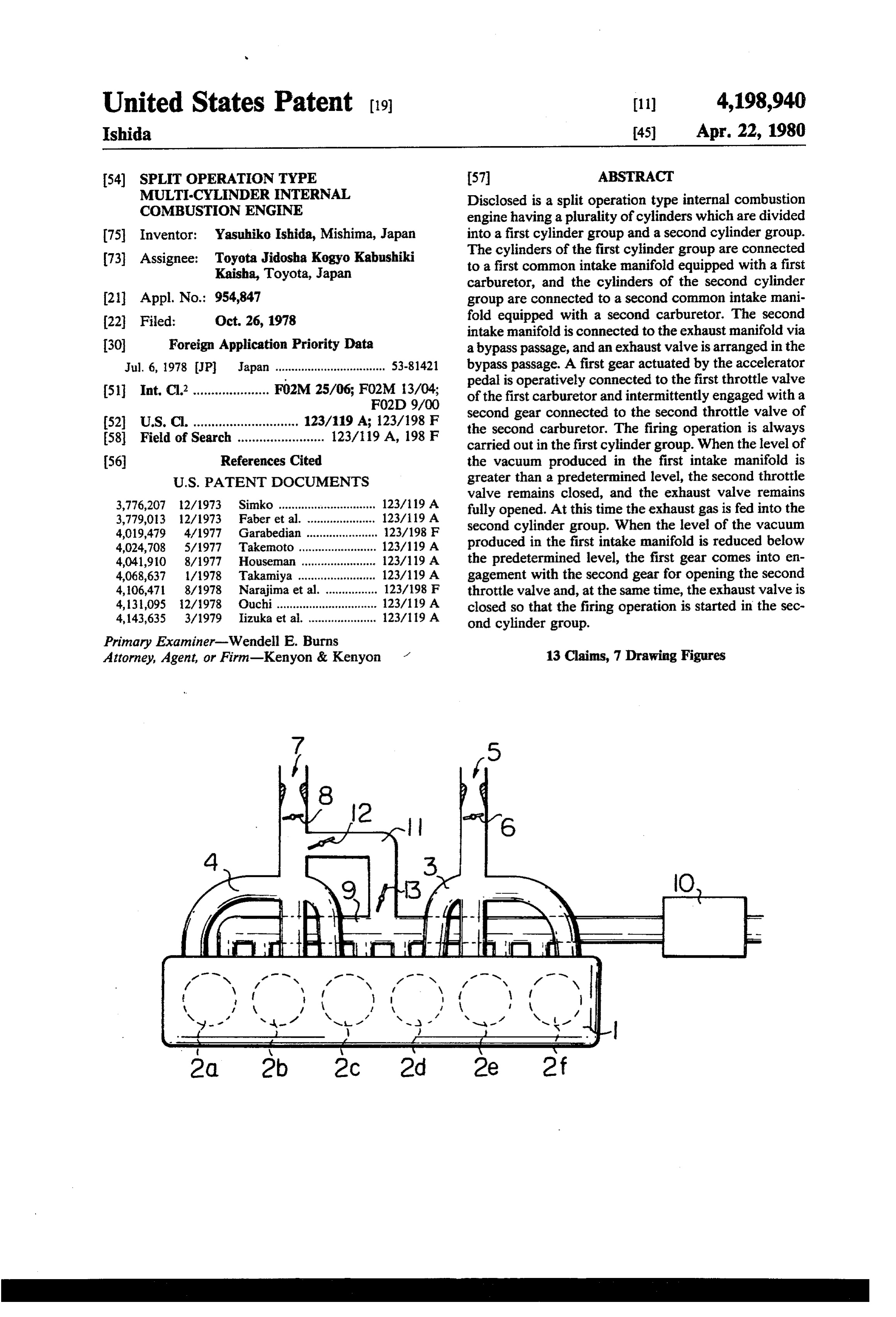
bypass passage. When the engine is operating under a FIG. 1 is a schematic view of an engine according to light load, the throttle valve of the second cylinder the present invention;
group is closed; in addition, the air valve is fully opened 60 so that air is directly introduced into the cylinders of the FIG. 2 is a plan view of an engine according to the second cylinder group from the atmosphere via the present invention;
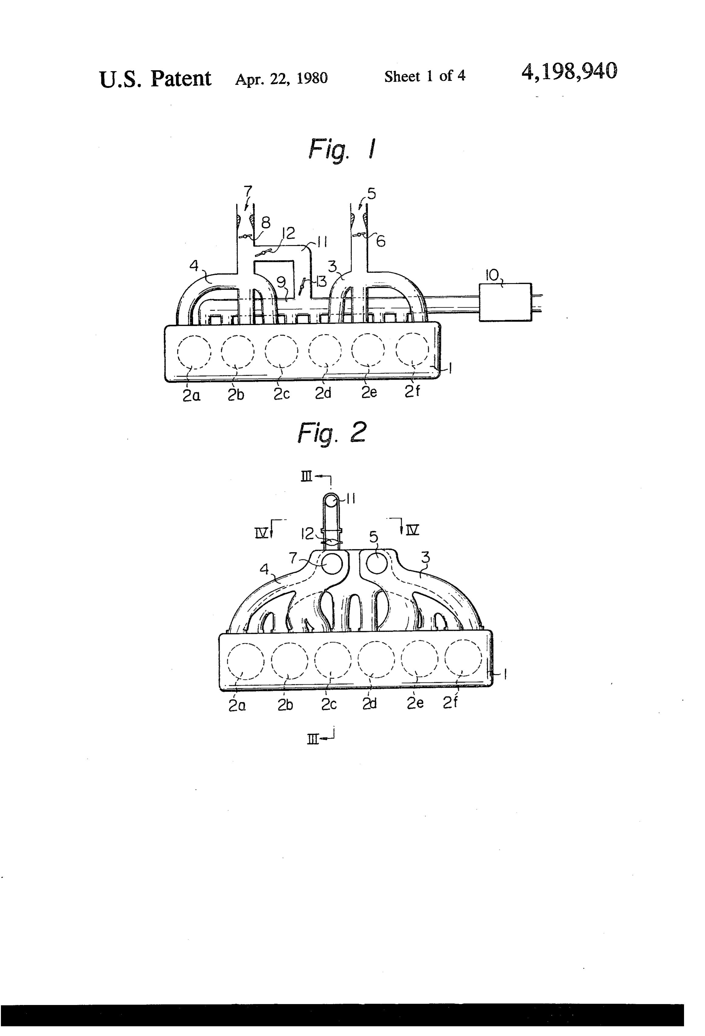
FIG. 3 is a cross-sectional view taken along the line bypass passage. On the other hand, when the engine is operating under a heavy load, the throttle valve of the III-III in FIG. 2;
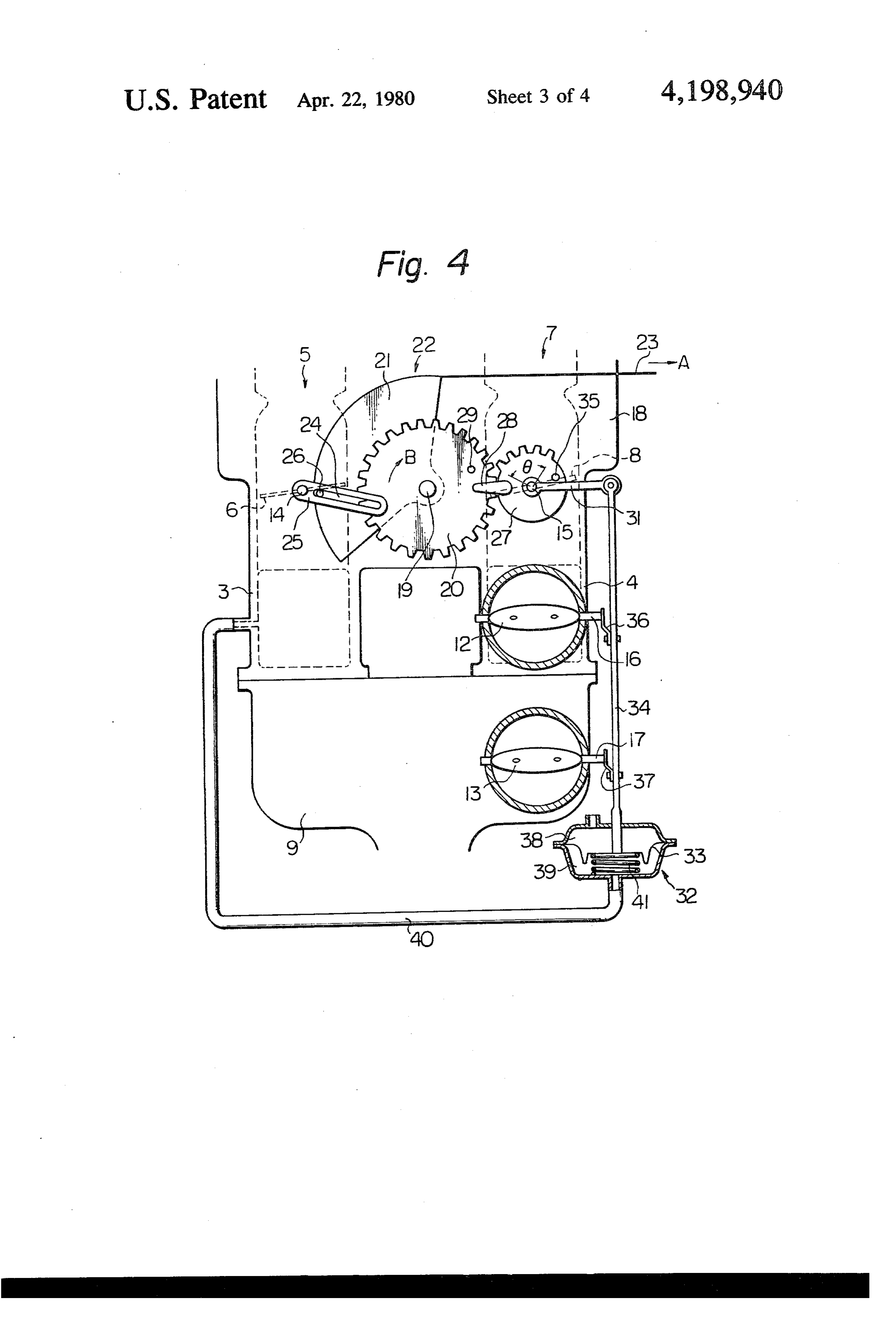
second cylinder group is opened; in addition, the air 65 theFIG. 4 is a side view of an intake device taken along line IV-V in FIG. 2;
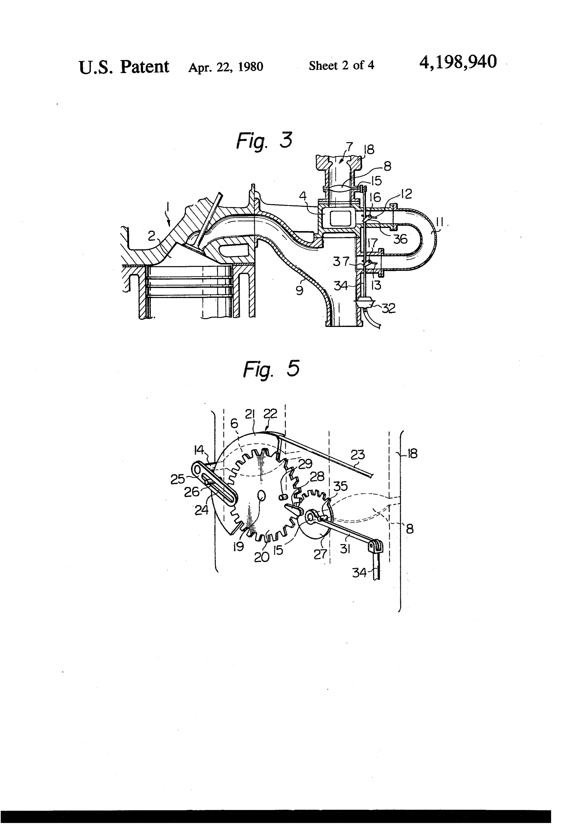
valve is closed for feeding an air-fuel mixture into the FIG. 5 is a perspective view of the intake device cylinders of the second cylinder group. In this engine, as is mentioned above, when the engine is operating shown in FIG. 4;
Page 7
FIG. 6 is a graph showing the relationship between valve 8 is normally positioned at a closed position as the depression of the accelerator pedal and the vacuum illustrated in FIG. 4. In this position, the gear 27 re produced in the intake manifold, and; mains disengaged from the gear 20. An arm 28 extend FIG. 7 is a graph showing the relationship between ing along the front face of the gear 20 is fixed onto the the depression of the accelerator pedal and the output 5 gear 27, and a pin 29 arranged to be engageable with the torque of an engine. arm 28 is fixed onto the gear 20. When the gear 27 is DESCRIPTION OF A PREFERRED rotated by an angle 6 from the position shown in FIG. EMBODIMENT 4, the second throttle valve 8 is fully opened. One end of a lever 31 is pivotably mounted on the
FIG. 1 is a schematic view of an engine according to 10 throttle shaft 15 of the second throttle valve 8, and the the present invention. Referring to FIG. 1, reference other end of the lever 31 is connected to the tip of a numeral 1 designates an engine body; 2a2b, 2c, 2d 2e, 2f control rod 34 which is fixed onto a diaphragm 33 of a designate a cylinder, 3 a first intake manifold common vacuum-operated diaphragm apparatus 32. On the other to a first cylinder group of 2d, 2e, 2f 4 designates a hand, a pin 35 arranged to be engageable with the lever second intake manifold common to a second cylinder 5 31 is fixed onto the gear 27. In addition, the tips of arms group of 2a, 2b, 2c 5 designates a first carburetor, 6 a 36 and 37, which are fixed onto the valve shafts 16 and first throttle valve of the first carburetor 5; 7 designates 17 of first and second exhaust valves 12 and 13, respec a second carburetor, 8 a second throttle valve of the tively, are pivotably connected to the control rod 34. second carburetor 7; 9 designates an exhaust manifold The diaphragm apparatus 32 comprises an atmospheric common to the cylinders 2a, 2b, 2c, 2d, 2e and 2f 10 20 pressure chamber 38 and a vacuum chamber 39 which designates an exhaust gas purifier such as a catalytic are separated by the diaphragm 33. The vacuum cham converter or a thermal reactor, 11 a bypass passage ber 39 is connected via a vacuum conduit 40 to the first communicating the second intake manifold 4 located intake manifold 3 located at a position downstream of downstream of the second throttle valve 8 with the the first throttle valve 6. In addition, a compression exhaust manifold 9 located upstream of the exhaust gas 25 spring 41 is inserted into the vacuum chamber 39 for purifier 10; 12 designates a first exhaust valve arranged always biasing the diaphragm 33 towards the atmo in the bypass passage 11 at a position near the second spheric pressure chamber 38.
intake manifold 4, and; 13 designates a second exhaust FIG. 4 illustrates the case wherein an engine is oper valve arranged in the bypass passage 11 at a position ating under an idling condition. When the accelerator near the exhaust manifold 9. FIGS. 2 and 3 are a plan 30 pedal (not shown) is depressed and, accordingly, the view and a cross-sectional side view of an engine ac pulley 21 is rotated in the direction of the arrow B, the cording to the present invention, respectively; FIG. 4 first throttle valve 6 is opened. At this time, as illus illustrates, an intake device of the engine illustrated in trated in FIG. 4, the second throttle valve 8 remains FIGS. 2 and 3, and; FIG. 5 is a perspective view of the completely closed, and the first exhaust valve 12 and intake device illustrated in FIG. 4. Referring to FIGS. 35 the second exhaust valve 13 remain fully opened. Con 2 through 5, reference numeral 14 designates a throttle sequently, the firing operation is carried out in the first shaft of the first throttle valve 6;15 designates a throttle cylinder group of 2d, 2e, 2fand, on the other hand, the shaft of the second throttle valve 8; 16 designates a exhaust gas is recirculated into the second cylinder valve shaft of the first exhaust valve 12; 17 designates a group of 2a, 2b, 2c via the bypass passage 11 and the valve shaft of the second exhaust valve 13, and; 18 second intake manifold 4. Consequently, at this time, designates a carburetor housing including the first car the firing operation is not carried out in the second buretor 5 and the second carburetor 7 therein. A pin 19 cylindergroup of 2a, 2b, 2c. In this case, since the recir is fixed onto the carburetor housing 18, and a gear 20 is culated exhaust gas of a high temperature is discharged rotatably mounted on the pin 19. A pulley 21 is fixed into the exhaust manifold 9 from the second cylinder onto the rear face of the gear 20, and a wire 23 con 45 group of 2a, 2b, 2c, the exhaust gas in the exhaust mani nected to an accelerator pedal (not shown) is wound on fold 9 is maintained at a high temperature. Thus, a satis a peripheral groove 22 formed on the pulley 21. Conse factory purifying operation of the exhaust gas in the quently, when the accelerator pedal is depressed and, exhaust manifold 9 and the exhaust gas purifier 10 can accordingly, the wire 23 is pulled in the direction be ensured. The level of the vacuum produced in the shown by the arrow A in FIG. 4, the gear 20 is rotated 50 first intake manifold 3 located at a position downstream in the direction shown by the arrow B in FIG. 4 to of the first throttle valve 6 is gradually reduced as the gether with the pulley 21. On the other hand, a lever 25 opening degree of the first throttle valve 6 is increased. forming a slit 24 thereon is fixed onto the throttle shaft When vacuum in the first intake manifold 3 becomes 14 of the first throttle valve 6, and a pin 26 fixed onto equal to a predetermined set level, the diaphragm 33 of the pulley 21 is fitted into the slit 24. Consequently, the 55 the diaphragm apparatus 32 moves upwards due to the first throttle valve 6 is opened as the pulley 21 is rotated spring force of the compression spring 41. As a result of in the direction of the arrow B. At this time, as is herein this, the first exhaust valve 12 and the second exhaust after described, the first throttle valve 6 is rapidly valve 13 is rotated to be completely closed and, at the opened during the first half of the rotation of the pulley same time, since the lever 31 pushes the pin 35 upwards, 21, and the first throttle valve 6 remains approximately the gear 27 is rotated in the counterclockwise direction, fully open during the latter half of the rotation of the whereby the teeth of the gear 27 come into engagement pulley 21. with the teeth of the gear 20. After this, when the accel As illustrated in FIG. 4, another gear 27 forming erator pedal is further depressed and, accordingly, the teeth on the outer pheriphery thereof, only within the gear 20 is rotated in the direction of the arrow B, the range of an angle 6, is fixed onto the throttle shaft 15 of 65 gear 27 is rotated in the counterclockwise direction by the second throttle valve 8. The throttle shaft 15 is the gear 20 and, as a reuslt, the second throttle valve 8 urged in the clockwise direction due to the spring force is gradually opened. Consequently, the firing operation of the spring (not shown) so that the second throttle of the engine is started in the second cylinder group of
Page 8
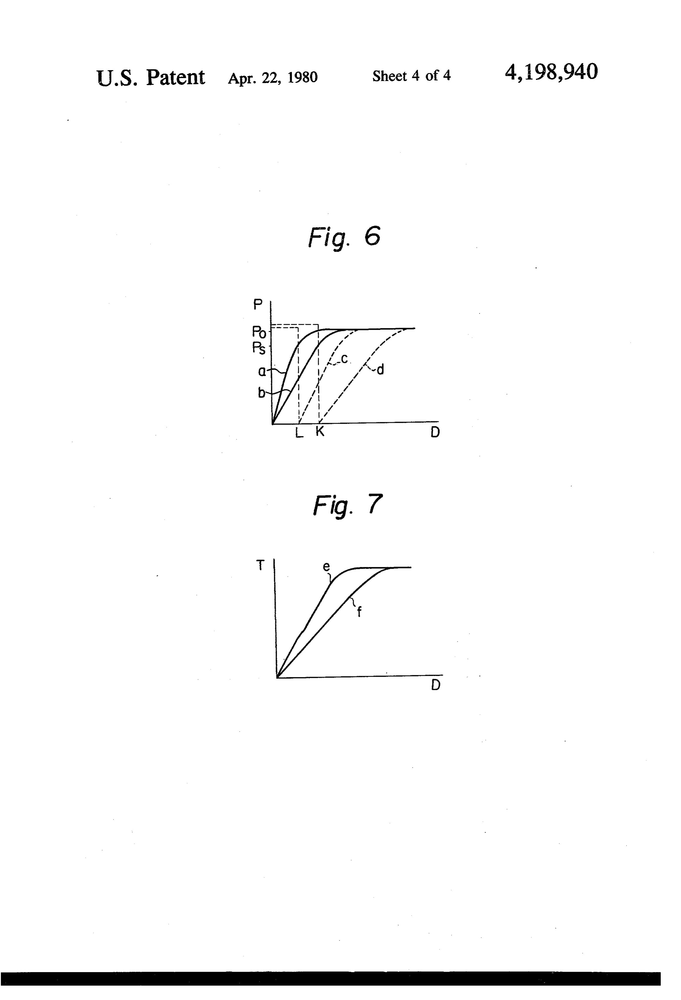
2a, 2b, 2c. When the second throttle valve 8 is rotated second intake manifold and, as a result, the output by an angle 8 from its closed position to become fully torque of the engine is reduced. However, in the present opened, opened, the gear 27 is disengaged from the gear invention, since the opening operation of the second 20. Consequently, after this, even if the gear 20 is fur throttle valve 8 is always carried out in synchronization ther rotated, the gear 27 remains stopped and the sec with the closing operation of the first and second ex ond throttle valve 8 remains fully opened. haust valves 12 and 13 independent of the speed of the FIG. 6 illustrates the relationship between the depres engine, a smooth increase in the output torque of the sion of the accelerator pedal and the level of the vac engine can be ensured, independent of the speed of the uum in the intake manifold, and FIG. 7 illustrates the engine, as illustrated in FIG. 7.
relationship between the depression of the accelerator 10 In the embodiment illustrated in FIGS. 4 and 5, there pedal and the output torque of the engine. In FIG. 6, the is a danger that, when the accelerator pedal is rapidly abscissa indicates the depression D of the accelerator depressed, the gear 27 cannot come into appropriate pedal, and the ordinate indicates the level of the abso engagement with the gear 20 due to presence of a time lute pressure P in the intake manifold. In addition, in lag in the operation of the diaphragm apparatus 32. In FIG. 6, Po of the ordinate indicates the atmospheric. 15 order to avoid occurrence of this danger, the arm 28 pressure, and Ps of the ordinate indicates a predeter and the pin 29 are provided in the present invention. mined set vacuum level at which the diaphragm begins That is, when the accelerator pedal is rapidly depressed, to move upwards due to the spring force of the com the pin 29 causes the arm 28 to move downward, pression spring. On the other hand, in FIG. 7, the ab whereby the gear 27 can come into engagement with scissa indicates the depression D of the accelerator 20 the gear 20. However, the gear 27 normally comes into pedal, and the ordinate indicates the output torque T of engagement with the gear 20 by means of the dia an engine. In FIG. 6, the curved line a indicates the phragm apparatus 32 before the pin 29 abuts against the vacuum level produced in the first intake manifold arm 28.
when the engine is operating at a low speed; the curved As is illustrated in FIGS. 3 and 4, a pair of the exhaust line bindicates the vacuum level produced in the first 25 valves 12, 13 is arranged in the bypass passage 11. How intake manifold when the engine is operating at a high ever, either of the first exhaust valve 12 or the second speed; the curved line c indicates the vacuum level exhaust valve 13 can be removed. Nevertheless, in the produced in the second intake manifold when the en case wherein only a single exhaust valve is arranged in gine is operating at a low speed; and the curved lined the bypass passage 11, since the single exhaust valve is indicates the vacuum level produced in the second in 30 always exposed to the exhaust gas having a high ten take manifold when the engine is operating at a high perature, the life time of the exhaust valve is shortened. speed. On the other hand, in FIG. 7, the curved line e Consequently, when the exhaust valve is used for a long indicates the output torque of the engine when the en time, it is difficult to prevent the exhaust gas from leak gine is operating at a low speed, and the curved line fof ing into the second intake manifold. Therefore, as is indicates the output torque of the engine when the en 35 illustrated in FIGS. 4 and 5, it is preferable that a pair of gine is operating at a high speed. the exhaust valves 12, 13 be arranged in the bypass In FIG. 6, the pressure in the first intake manifold passage 11. That is, by arranging a pair of the exhaust becomes approximately equal to the atmospheric pres valves 12, 13 in the bypass passage 11, since the first sure Po when the first throttle valve is fully opend. exhaust valve 12 is not directly exposed to the exhaust Consequently, from FIG. 6, it will be understood that gas having a high temperature when the second exhaust the first throttle valve is rapidly opened during the first valve 13 is closed, the life time of the first exhaust valve half of the depression of the accelerator pedal, and the 12 can be improved. As a result of this, the function of first throttle valve remains approximately fully open preventing the leakage of the exhaust gas can be en during the latter half of the depression of the accelera sured for a long time.
tion pedal. In addition, from FIG. 6, it will be under 45 According to the present invention, since the exhaust stood that the depression D of the accelerator pedal, gas having a high temperature is recirculated into the that is, the opening degree of the first throttle valve, in cylinders of the second cylinder group when an engine which the vacuum corresponding to the predetermined is operating under a light load, the exhaust gas in the set level Ps is produced in the first intake manifold, is exhaust manifold and the exhaust gas purifier is main increased as the speed of the engine is increased. 50 tained at a high temperature. This results in ensuring a As is mentioned previously, a conventional engine is good purifying operation of the exhaust gas. In addi so constructed that the opening operation of the second tion, in the embodiment illustrated in FIG. 1, only the throttle valve is started when the depression D of the exhaust gas is fed into the cylinders of the secohd cylin accelerator pedal becomes equal to, for example, the dergroup when the firing operation is not carried out in depression indicated by K in FIG. 6. Consequently, 55 the second cylinder group. However, in the case when the engine is operating at a high speed as shown wherein the temperature of the exhaust gas is exces by the curved line b, no problem occurs because the sively increased by feeding only the exhaust gas into the opening operation of the second throttle valve is started cylinders of the second cylinder group, the mixture of at the same time that the air valve arranged in the by the exhaust gas and an ambient air may be fed into the pass passage is closed. However, when the engine is 60 cylinders of the second cylinder group. Furthermore, operating at a low speed as indicated by the curved line when the firing operation is carried out in the second a in FIG. 6, the air valve is closed when the depression cylinder group, the exhaust valves 12, 13 may remain D of the accelerator pedal is increased beyond the de slightly opened to feed a small amount of the exhaust pression shown by L in FIG. 6. Consequently, since gas into the cylinders of the second cylinder group for both the second throttle valve and the air valve remain 65 reducing the amount of harmful NO components pro closed when the depression D of the accelerator pedal is duced in the cylinders of the second cylinder group. within the range of between L and K shown in FIG. 6, Although the invention has been described above the intake throttling loss is considerably increased in the with reference to a specific embodiment chosen for
Page 9
purposes of illustration, it should be apparent that nu ber to come into engagement with said first rotary merous modifications could be made thereto by those member when the level of the vacuum produced in said skilled in the art without departing from the spirit and first intake passage is reduced below said predetermined scope of the invention. level.
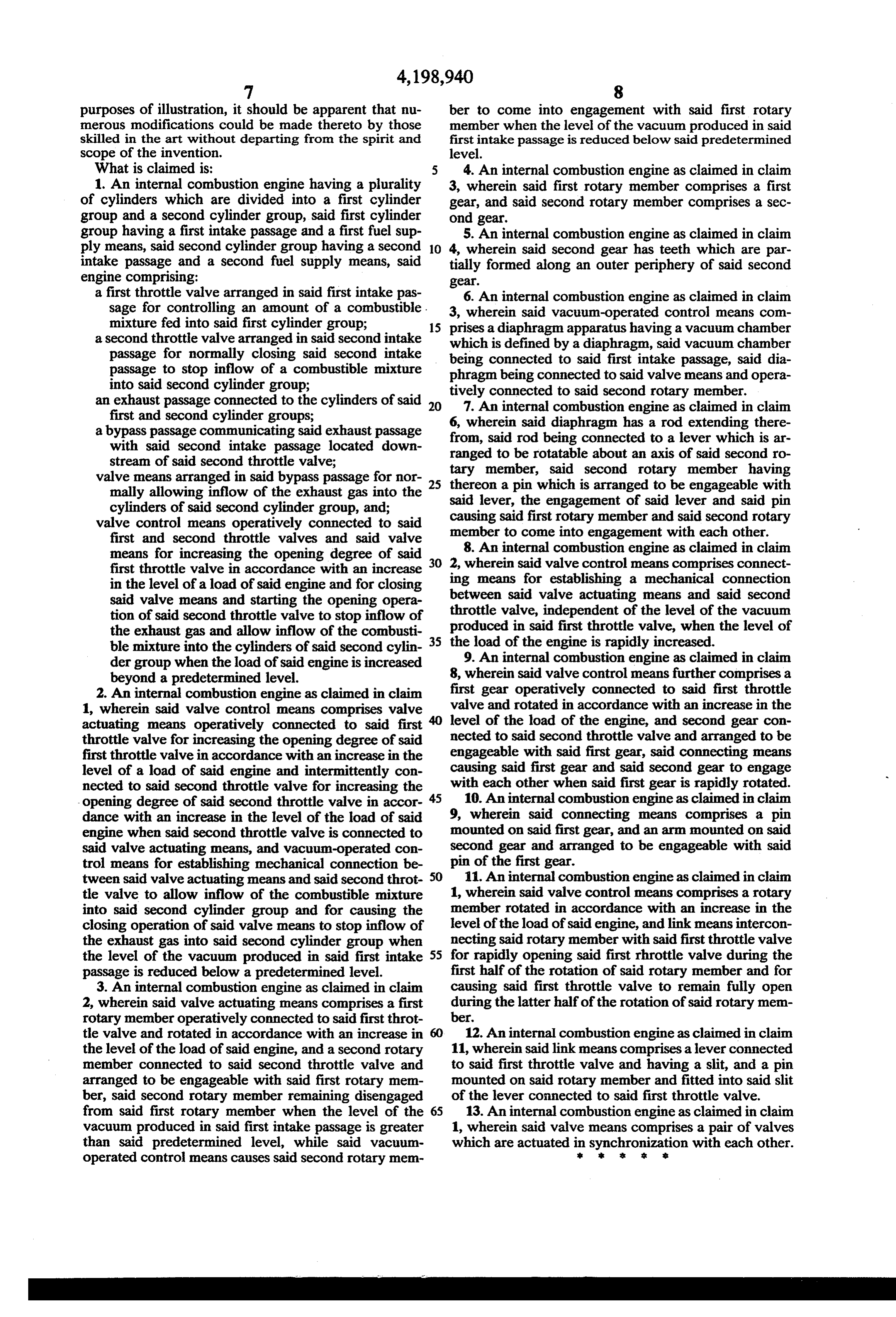
What is claimed is: 4. An internal combustion engine as claimed in claim 1. An internal combustion engine having a plurality 3, wherein said first rotary member comprises a first of cylinders which are divided into a first cylinder gear, and said second rotary member comprises a sec group and a second cylinder group, said first cylinder ond gear.
group having a first intake passage and a first fuel sup 5. An internal combustion engine as claimed in claim ply means, said second cylindergroup having a second 10 4, wherein said second gear has teeth which are par intake passage and a second fuel supply means, said tially formed along an outer periphery of said second engine comprising: gear.
a first throttle valve arranged in said first intake pas sage for controlling an amount of a combustible. 3, 6.wherein An internal combustion engine as claimed in claim said vacuum-operated control means com mixture fed into said first cylinder group; 15 prises a diaphragm apparatus having a vacuum chamber a second throttle valve arranged in said second intake which is defined by a diaphragm, said vacuum chamber passage for normally closing said second intake being connected to said first intake passage, said dia passage to stop inflow of a combustible mixture phragm being connected to said valve means and opera into said second cylinder group;
an exhaust passage connected to the cylinders of said 20 tively7.
connected to said second rotary member.
An internal combustion engine as claimed in claim first and second cylinder groups;
a bypass passage communicating said exhaust passage 6, wherein said diaphragm has a rod extending there with said second intake passage located down from, said rod being connected to a lever which is ar ranged to be rotatable about an axis of said second ro stream of said second throttle valve;
valve means arranged in said bypass passage for nor 25 tary thereon member, said second rotary member having a pin which is arranged to be engageable with mally allowing inflow of the exhaust gas into the said lever, the engagement of said lever and said pin cylinders of said second cylinder group, and; causing said first rotary member and said second rotary valve control means operatively connected to said member to come into engagement with each other. first and second throttle valves and said valve means for increasing the opening degree of said 30 8. An internal combustion engine as claimed in claim first throttle valve in accordance with an increase 2, wherein said valve control means comprises connect in the level of a load of said engine and for closing ing means for establishing a mechanical connection said valve means and starting the opening opera between said valve actuating means and said second throttle valve, independent of the level of the vacuum tion of said second throttle valve to stop inflow of produced the exhaust gas and allow inflow of the combusti 35 the load ofinthe said first throttle valve, when the level of engine is rapidly increased.
ble mixture into the cylinders of said second cylin dergroup when the load of said engine is increased 9. An internal combustion engine as claimed in claim beyond a predetermined level. 8, wherein said valve control means further comprises a 2. An internal combustion engine as claimed in claim first gear operatively connected to said first throttle 1, wherein said valve control means comprises valve valve and rotated in accordance with an increase in the actuating means operatively connected to said first level of the load of the engine, and second gear con throttle valve for increasing the opening degree of said nected to said second throttle valve and arranged to be first throttle valve in accordance with an increase in the engageable with said first gear, said connecting means level of a load of said engine and intermittently con causing said first gear and said second gear to engage nected to said second throttle valve for increasing the with each other when said first gear is rapidly rotated. - opening degree of said second throttle valve in accor 45 10. An internal combustion engine as claimed in claim dance with an increase in the level of the load of said 9, wherein said connecting means comprises a pin engine when said second throttle valve is connected to mounted on said first gear, and an arm mounted on said said valve actuating means, and vacuum-operated con second gear and arranged to be engageable with said trol means for establishing mechanical connection be pin of the first gear.
tween said valve actuating means and said second throt 50 11. An internal combustion engine as claimed in claim tle valve to allow inflow of the combustible mixture 1, wherein said valve control means comprises a rotary into said second cylinder group and for causing the member rotated in accordance with an increase in the closing operation of said valve means to stop inflow of level of the load of said engine, and link means intercon the exhaust gas into said second cylinder group when necting said rotary member with said first throttle valve the level of the vacuum produced in said first intake 55 for rapidly opening said first rhrottle valve during the passage is reduced below a predetermined level. first half of the rotation of said rotary member and for 3. An internal combustion engine as claimed in claim causing said first throttle valve to remain fully open 2, wherein said valve actuating means comprises a first during the latter half of the rotation of said rotary mem rotary member operatively connected to said first throt ber.
tle valve and rotated in accordance with an increase in 12. An internal combustion engine as claimed in claim the level of the load of said engine, and a second rotary 11, wherein said link means comprises a lever connected member connected to said second throttle valve and to said first throttle valve and having a slit, and a pin arranged to be engageable with said first rotary mem mounted on said rotary member and fitted into said slit ber, said second rotary member remaining disengaged of the lever connected to said first throttle valve. from said first rotary member when the level of the 65 13. An internal combustion engine as claimed in claim vacuum produced in said first intake passage is greater 1, wherein said valve means comprises a pair of valves than said predetermined level, while said vacuum which are actuated ins synchronization with each other. operated control means causes said second rotary mem
Page 10
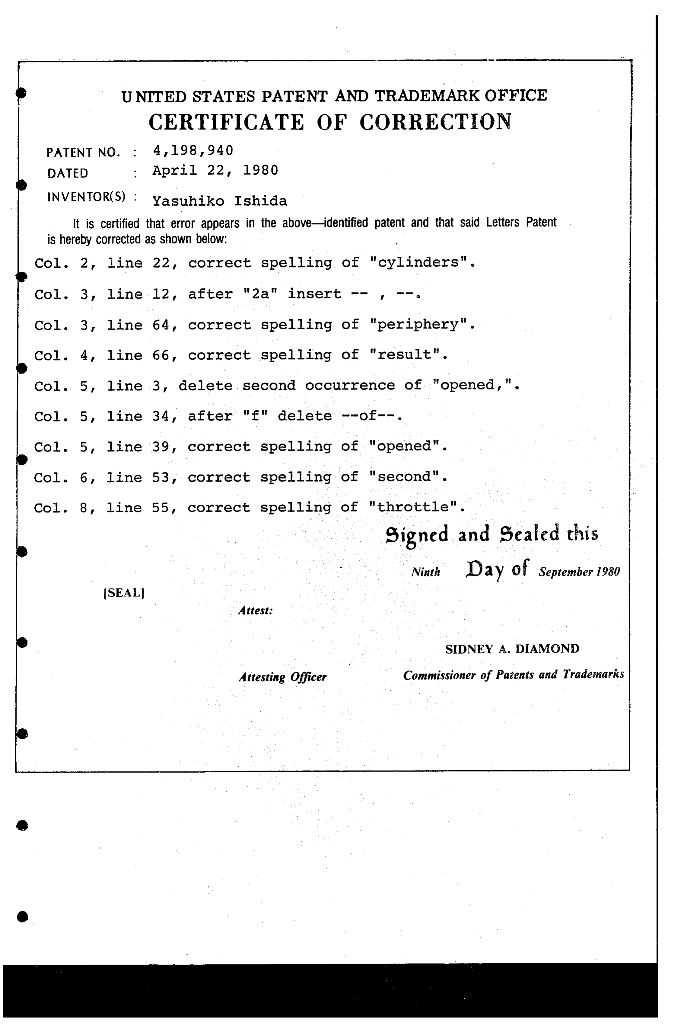
UNITED STATES PATENT AND TRADEMARK OFFICE
CERTIFICATE OF CORRECTION
INVENTOR(S) : Yasuhiko Ishida
It is Certified that error appears in the above-identified patent and that said Letters Patent is hereby corrected as shown below:
Col. 2, line 22, correct spelling of "cylinders".
Col. 3, line 64, correct spelling of "periphery". Col. 4, line 66, correct spelling of "result". Col. 5, line 3, delete second occurrence of "opened, ". Col. 5, line 34, after "f" delete --of--. Col. 5, line 39, correct spelling of "opened". Col. 6, line 53, correct spelling of "second". Col. 8, line 55, correct spelling of "throtte" eigned and sealed this
Ninth D 2 y of September 1980
SEAL
SIDNEY A. DAMOND
Attesting Officer Commissioner of Patents and Trademarks
Provenance
- Collection
- Cited prior art
- Original PDF
- patentimages.storage.googleapis.com →
- Filed
- 1978-10-26
- Pages
- 10
- Method
- pdftotext (the PDF's own text layer) + pdftoppm 300dpi page scans
- Source
- Google Patents bibliographic record
- Granted
- 1980-04-22
- Inventors
- Yasuhiko Ishida; Toyota Jidosha Kogyo KK
- Transcribed from
- patentimages.storage.googleapis.com →