patent · US3924576
Staged combustion engines and methods of operation
9 December 1975
Page 1
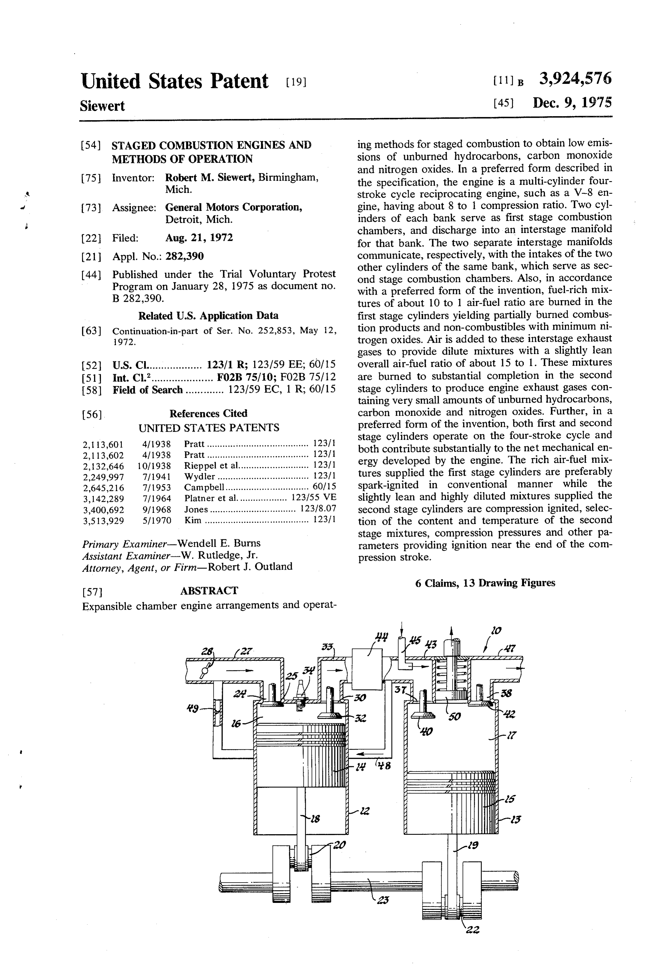
United States Patent (19) (11): 3,924,576 Siewert (45) Dec. 9, 1975 (54) STAGED COMBUSTION ENGINES AND ing methods for staged combustion to obtain low emis METHODS OF OPERATION sions of unburned hydrocarbons, carbon monoxide and nitrogen oxides. In a preferred form described in 75 Inventor: Robert M. Siewert, Birmingham, the specification, the engine is a multi-cylinder four Mich. stroke cycle reciprocating engine, such as a V-8 en 73 Assignee: General Motors Corporation, gine, having about 8 to 1 compression ratio. Two cyl Detroit, Mich. inders of each bank serve as first stage combustion
chambers, and discharge into an interstage manifold for that bank. The two separate interstage manifolds (21) Appl. No.: 282,390 communicate, respectively, with the intakes of the two (44) Published under the Trial Voluntary Protest other cylinders of the same bank, which serve as sec Program on January 28, 1975 as document no. ond stage combustion chambers. Also, in accordance
with a preferred form of the invention, fuel-rich mix tures of about 10 to 1 air-fuel ratio are burned in the
Related U.S. Application Data first stage cylinders yielding partially burned combus (63) Continuation-in-part of Ser. No. 252,853, May 12, tion products and non-combustibles with minimum ni 1972. trogen oxides. Air is added to these interstage exhaust gases to provide dilute mixtures with a slightly lean 52 U.S. Cl................... 123/1 R; 123/59 EE; 60/15 overall air-fuel ratio of about 15 to 1. These mixtures 51) Int. C.’..................... F02B 75/10; FO2B 75/12 are burned to substantial completion in the second 58) Field of Search ............. 123/59 EC, 1 R; 60/15 stage cylinders to produce engine exhaust gases con taining very small amounts of unburned hydrocarbons, 56) References Cited carbon monoxide and nitrogen oxides. Further, in a UNITED STATES PATENTS preferred form of the invention, both first and second 2,113,601 4/1938 Pratt....................................... 1231 stage cylinders operate on the four-stroke cycle and 2,113,602 4/1938 Pratt....................................... 1231 both contribute substantially to the net mechanical en 2,132,646 10/1938 Rieppel et al........................... 12311 ergy developed by the engine. The rich air-fuel mix 2,249,997 7/1941 Wydler ........... ... 12311 tures supplied the first stage cylinders are preferably 2,645,216 7/1953 Campbell................................ 60/15 spark-ignited in conventional manner while the 3, 142,289 7/1964 Platner et al... ... 123/55 VE slightly lean and highly diluted mixtures supplied the 3,400,692 9/1968 Jones................................. 23/8.07 second stage cylinders are compression ignited, selec 3,513,929 5/1970 Kim ....................... ---- - 2311 tion of the content and temperature of the second stage mixtures, compression pressures and other pa
Primary Examiner-Wendell E. Burns rameters providing ignition near the end of the com Assistant Examiner-W. Rutledge, Jr. pression stroke.
Attorney, Agent, or Firm-Robert J. Outland 6 Claims, 13 Drawing Figures
Expansible chamber engine arrangements and operat
mamm.
Page 2
Drawing sheet — no readable text.
Page 3
Drawing sheet — no readable text.
Page 4
Drawing sheet — no readable text.
Page 5
Drawing sheet — no readable text.
Page 6
Drawing sheet — no readable text.
Page 7
Drawing sheet — no readable text.
Page 8
STAGED COMBUSTION ENGINES AND METHODS. connected by suitable crank mechanism to the same OF OPERATION crankshaft as the piston or rotor of the first stage cham
APPLICATION 5. Expanding the products of the second stage com bustion with a resultant output of power to the crank
This application is a continuation-in-part of my appli shaft, cation of the same title filed May 12, 1972, Ser. No. The air-fuel mixture ratio in the first stage is selected 252,853 assigned to the same assignee as the present to minimize overall emissions of nitrogen oxides. If the
mixture is not sufficiently rich, unnecessarily high
DESCRIPTION OF THE INVENTION amounts of nitrogen oxides will be produced in the first combustion stage. If, however, the mixture is too rich,
The present invention provides an improved engine there will be insufficient burned gases resulting from arrangement and methods of engine operation charac the first stage combustion to adequately dilute the 'terized by two-stage combustion in expansible cham 15 charge in the second stage. Tests have indicated that, bers that expand and contract in synchronism and each for the preferred operational method described, oxides supplies net energy per cycle, preferably to a common of nitrogen emissions are minimized by selection of a rotating shaft. The first stage is preferably spark ignited first stage air-fuel ratio of about ten and one-half to one and the second stage is compression ignited. Fuel-rich (10.5:1). Various other ratios may, however, be prefer combustion occurs in the first stage with minimal nitro 20 able under varying conditions of operation, including, gen oxide production. Slightly fuel-lean combustion for example, use of different mixture constituents or occurs in the second stage with resultant minimizing of variations in the operating method. hydrocarbon and carbon monoxide emissions. Also, Variations of the method may include the use of the presence of partially burned products in the second exhaust gas recirculation, from either between the stage mixture limits combustion temperatures so that 25 stages or from the final exhaust, to the inlet of the first nitrogen oxides are not significantly increased in this stage for mixture with the initial charge to yield even Stage. lower emissions of nitrogen oxides. The method of the present invention includes the The interstage conditioning step involves adding air steps of: to the first stage combustion products. It may also in 1. Burning in one chamber of an expansible chamber volve adding exhaust products or other diluents to the reciprocating or rotary internal combustion engine a 30 mixture, heating or cooling of the mixture, adding com compressed combustible mixture including air and bustion stimulants or retardants, or other changes to hydrocarbon fuel, said burning comprising a first stage provide the proper conditions for subsequent compres of combustion and said mixture being richer in fuel sion and burning with the desired efficiency. Control of than a stoichiometric mixture by amount sufficient to 35 the mixture temperature between stages should be such yield combustion products low in oxides of nitrogen as to promote initiation of second stage combustion by (NO) but high in incompletely burned combustibles, auto-ignition at the most favorable point in the cycle largely hydrogen (H) and carbon monoxide (CO). The (shortly before the end of compression and beginning air-fuel ratio in this stage is preferably about 10 to 1. In of expansion) and to prevent substantial oxidation of this first stage, the chamber is preferably operated on the combustibles before this point. Tests have shown the known four-stroke cycle with spark ignition of the 40 that there is an optimum range of interstage tempera compressed mixture; ture for a specific engine and operation condition, as 2. Expanding the resulting combustion products discussed hereafter.
to supply power to the usual crank-shaft of a recipro Control of the timing of second stage burning may be cating or rotary engine apparatus; aided by varying or controlling the compression ratio 3. Conditioning the expanded combustion products 45 or the compression pressure reached during the com of the first stage at least by the addition of air, so as to pression stroke of the second stage portion of the cycle. prepare a new mixture capable of further power-pro The method of the present invention may be carried ducing combustion. This mixture is characterized by out in engines of a number of different forms in which substantially less energy content than the charge in the power is obtained from the burning of combustibles first chamber, since the hydrocarbon fuel has been 50 within an expansible combustion chamber. Included, partially burned. In accordance with a preferred form for example, are reciprocating piston engines and ro of the present invention, the amount of air in the newly tary piston engines, each of which utilizes variable formed mixture is such as to provide about a 15 to 1 volume working and combustion chambers, together overall engine air-fuel ratio, or only slightly in excess of with suitable crankshaft mechanism. the stoichiometric quantity of air required for complete 55 The presently preferred arrangement for utilizing the combustion of the fuel; method in an engine involves the use of two working 4. Recompressing the new mixture in an expansible chambers or sets of working chambers connected in chamber of the reciprocating or rotating internal com series with the first stage combustion taking place in bustion engine sufficiently to initiate second stage com one chamber and the second stage combustion in the bustion by auto-ignition, and burning the mixture with 60 other. Preferably, both chambers will be operated on out substantial additional compression. The point of the conventional four-stroke cycle or its equivalent. ignition of the mixture may be maintained near the end However, operation of one or both chambers on a of the compression step by appropriate choice of the two-stroke cycle is also possible. Additionally, it is compression ratio of the second stage chamber, heating 65 within the scope of the invention to perform both com or cooling the mixture between the stages or by the bustion stages sequentially in the same combustion addition of other substances thereto as a part of the chamber which might, for example, be operated on a conditioning step before second stage compression. In six-stroke cycle. In multi-cylinder or multi-chamber accordance with a preferred form of the present inven engine arrangements, it is possible to arrange for the tion, the expansible chamber of the second stage passes first stage combustion chambers to feed one or more through a four-stroke cycle and its piston or rotor is interstage manifolds, which in turn distribute the prod
Page 9
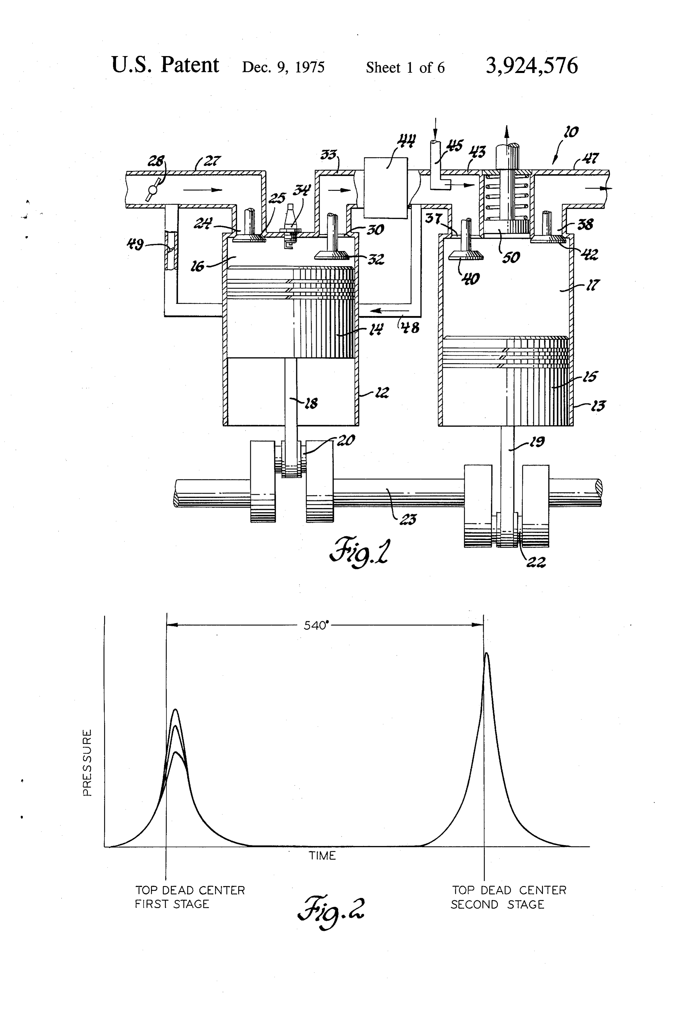
ucts to the second stage combustion chambers after vided in the inlet conduit 43 for purposes to be subse undergoing the appropriate conditioning treatment. quently described. The exhaust port 38 of cylinder 2 There is provided a first stage of fuel-rich combus connects with an exhaust conduit 47. An exhaust recir tion, and work-producing expansion, yielding low re 5 culation conduit 48 connects inlet conduit 27 directly siduals of nitrogen oxides but with little control of com with the second stage inlet conduit 43. A valve 49 is bustibles. This is followed by a second stage of combus provided for controlling the amount of flow permitted tion and work-producing expansion, before which the through the recirculation conduit. If desired, the recir mixture is conditioned to aid proper timing of its igni culation conduit could be connected with the second tion and provide substantial elimination of combusti stage exhaust conduit 47, rather than the interstage bles in the combustion step without significantly in inlet conduit 43. A movable piston 50 is provided in the creasing nitrogen oxides. The overall result is an engine end wall of cylinder 13 so as to provide for varying the and method producing low emissions of combustibles compression ratio of the cylinder during operation. and nitrogen oxides in the exhaust with the added bene In operation, power delivered to the pistons causes fit of relatively good efficiency due to the production of 5 rotation of the cranksahift 23, timing the movements of substantial work from both combustion stages. the pistons 13, 14 within their respective cylinders in an These and other advantages of the invention, as well out-of-phase reciprocating motion. Each piston-cylin as various additional modifications of the operating der combination follows a four-stroke operating cycle, methods and structures for performing such methods. including the usual events of intake, compression, ex will be more completely understood from the following 20 pansion and exhaust, the exhaust stroke of piston 14 description of certain preferred embodiments, taken coinciding with the intake stroke of piston 5. Thus, together with the accompanying drawings. piston 15 is timed 540 after piston 14 as regards their operations on a particular inlet charge to cylinder 2,
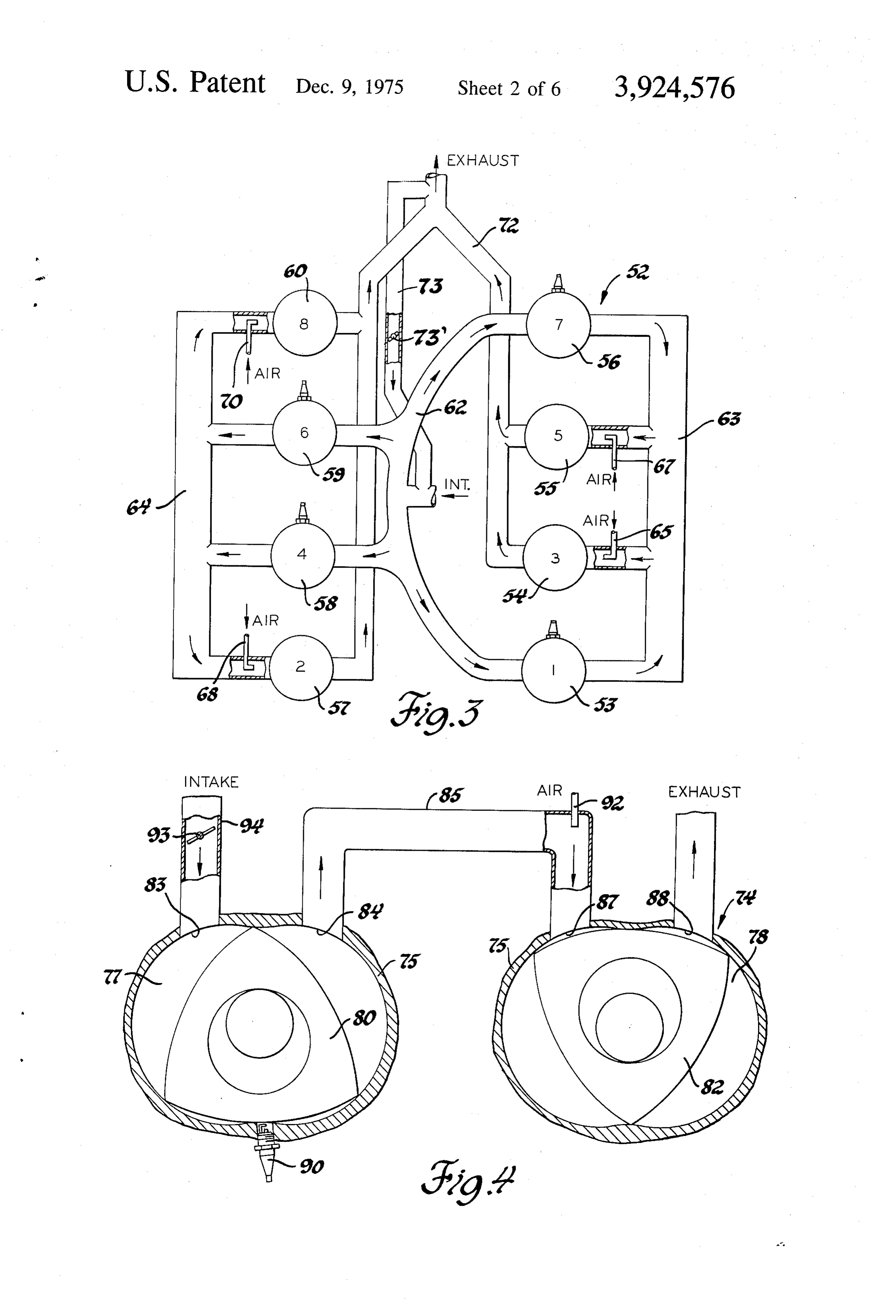
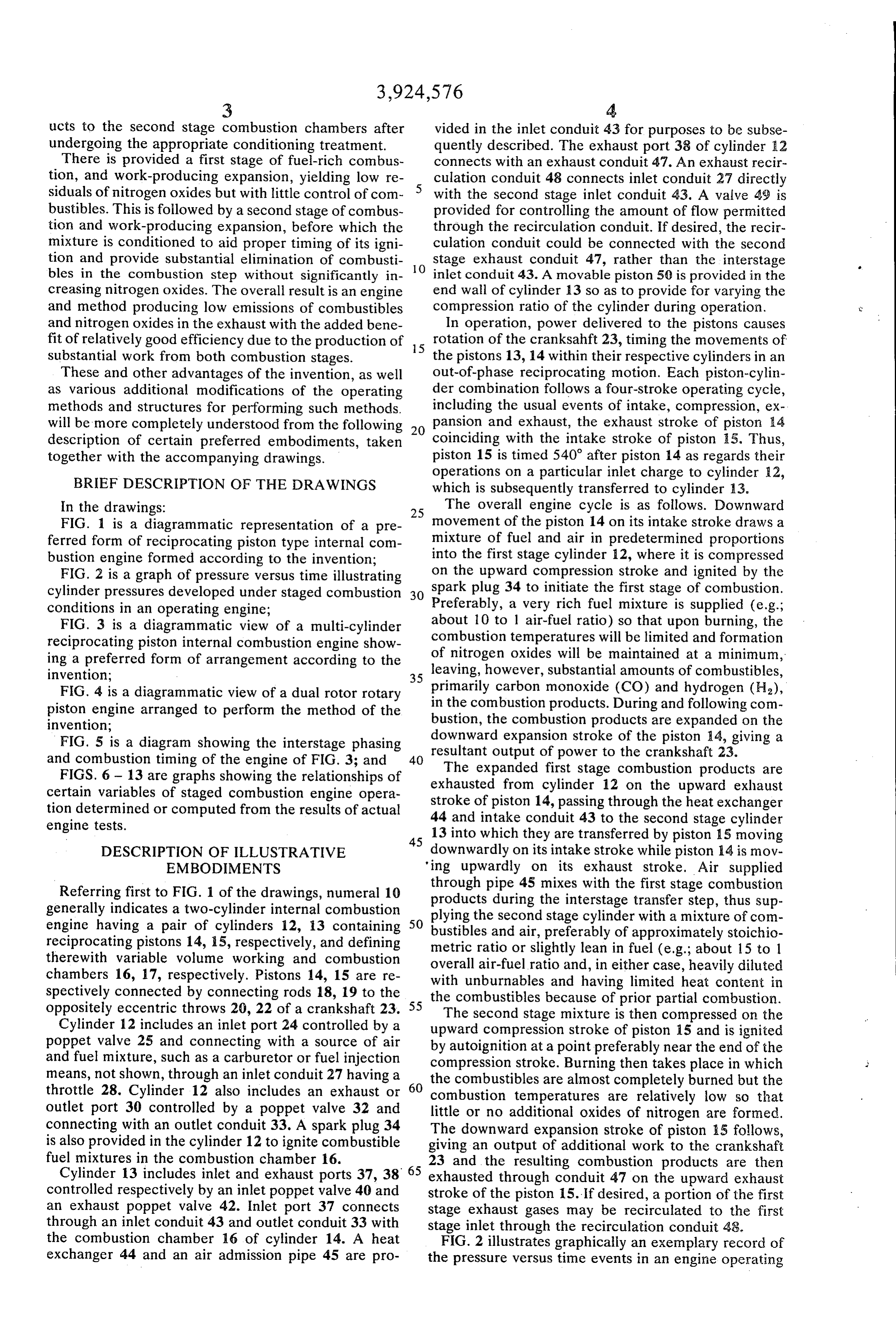
BRIEF DESCRIPTION OF THE DRAWINGS which is subsequently transferred to cylinder 13. In the drawings: 25 The overall engine cycle is as follows. Downward FIG. 1 is a diagrammatic representation of a pre movement of the piston 14 on its intake stroke draws a ferred form of reciprocating piston type internal com mixture of fuel and air in predetermined proportions bustion engine formed according to the invention; into the first stage cylinder 12, where it is compressed FIG. 2 is a graph of pressure versus time illustrating on the upward compression stroke and ignited by the cylinder pressures developed under staged combustion 30 spark plug 34 to initiate the first stage of combustion. conditions in an operating engine; Preferably, a very rich fuel mixture is supplied (e.g.; FIG. 3 is a diagrammatic view of a multi-cylinder about 10 to 1 air-fuel ratio) so that upon burning, the reciprocating piston internal combustion engine show combustion temperatures will be limited and formation ing a preferred form of arrangement according to the of nitrogen oxides will be maintained at a minimum, invention; 35 leaving, however, substantial amounts of combustibles, FIG. 4 is a diagrammatic view of a dual rotor rotary in primarily carbon monoxide (CO) and hydrogen (H), piston engine arranged to perform the method of the bustion, the combustion products. During and following com invention; the combustion products are expanded on the downward
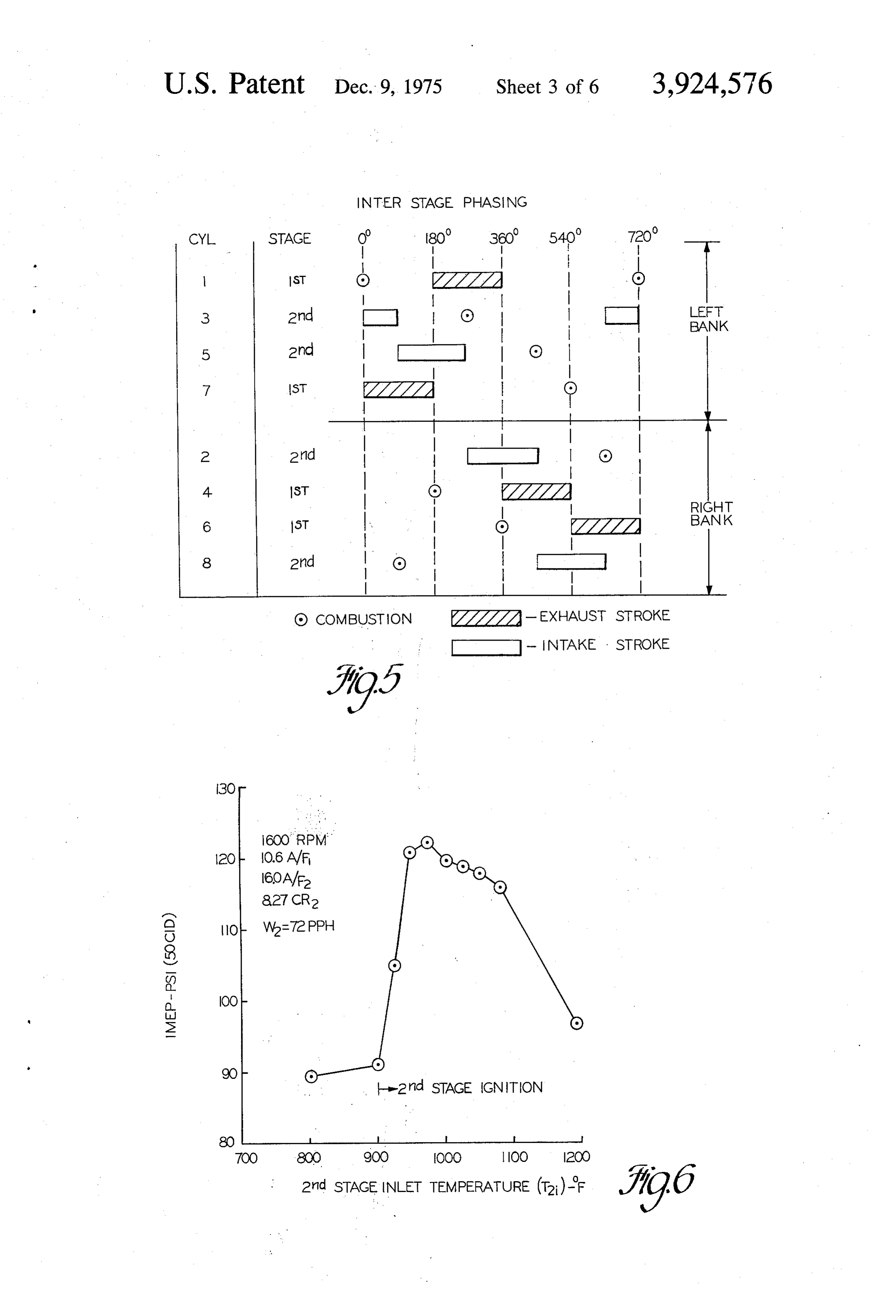
FIG. 5 is a diagram showing the interstage phasing resultant output expansion stroke of the piston 14, giving a and combustion timing of the engine of FIG. 3; and 40 of power to the crankshaft 23. The expanded
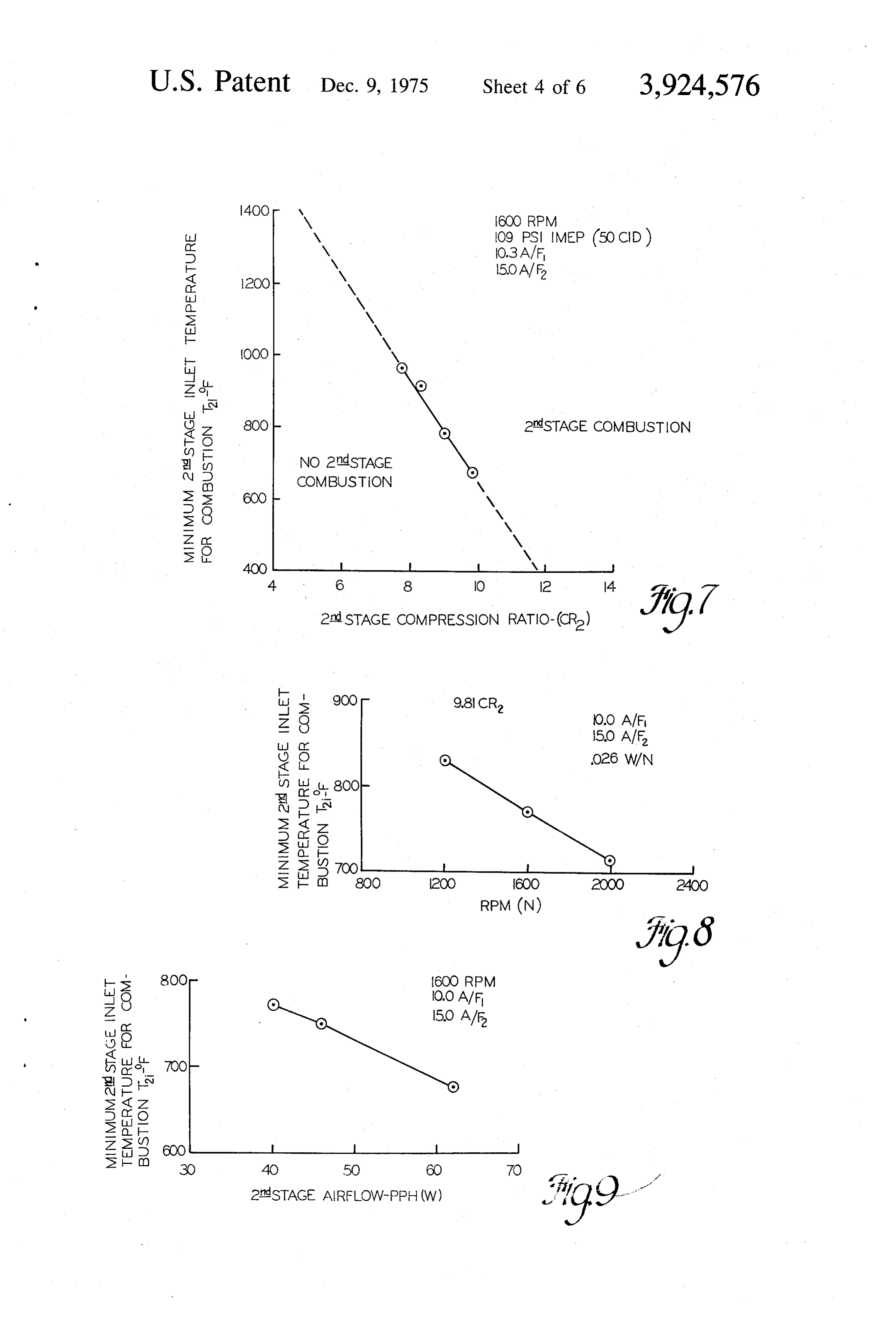
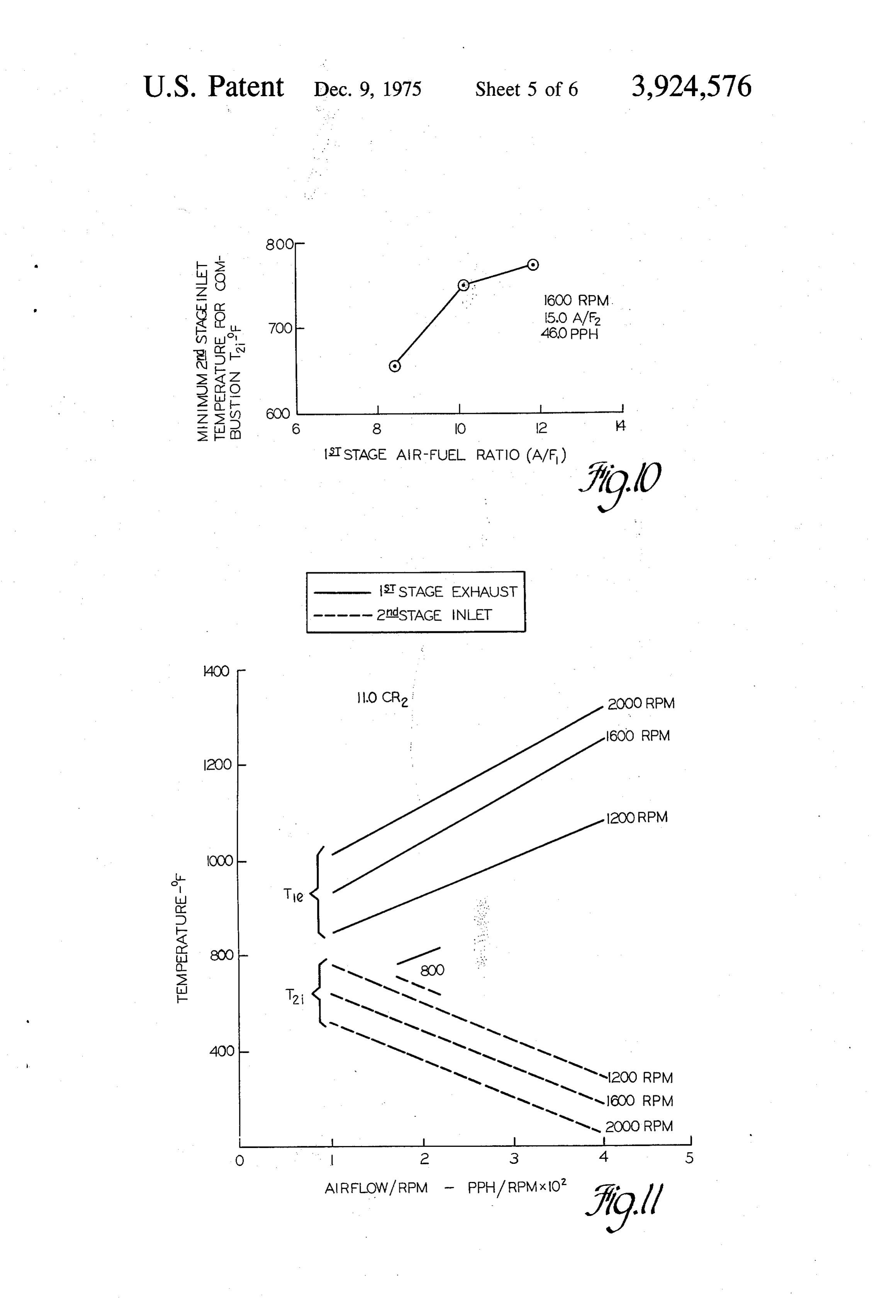
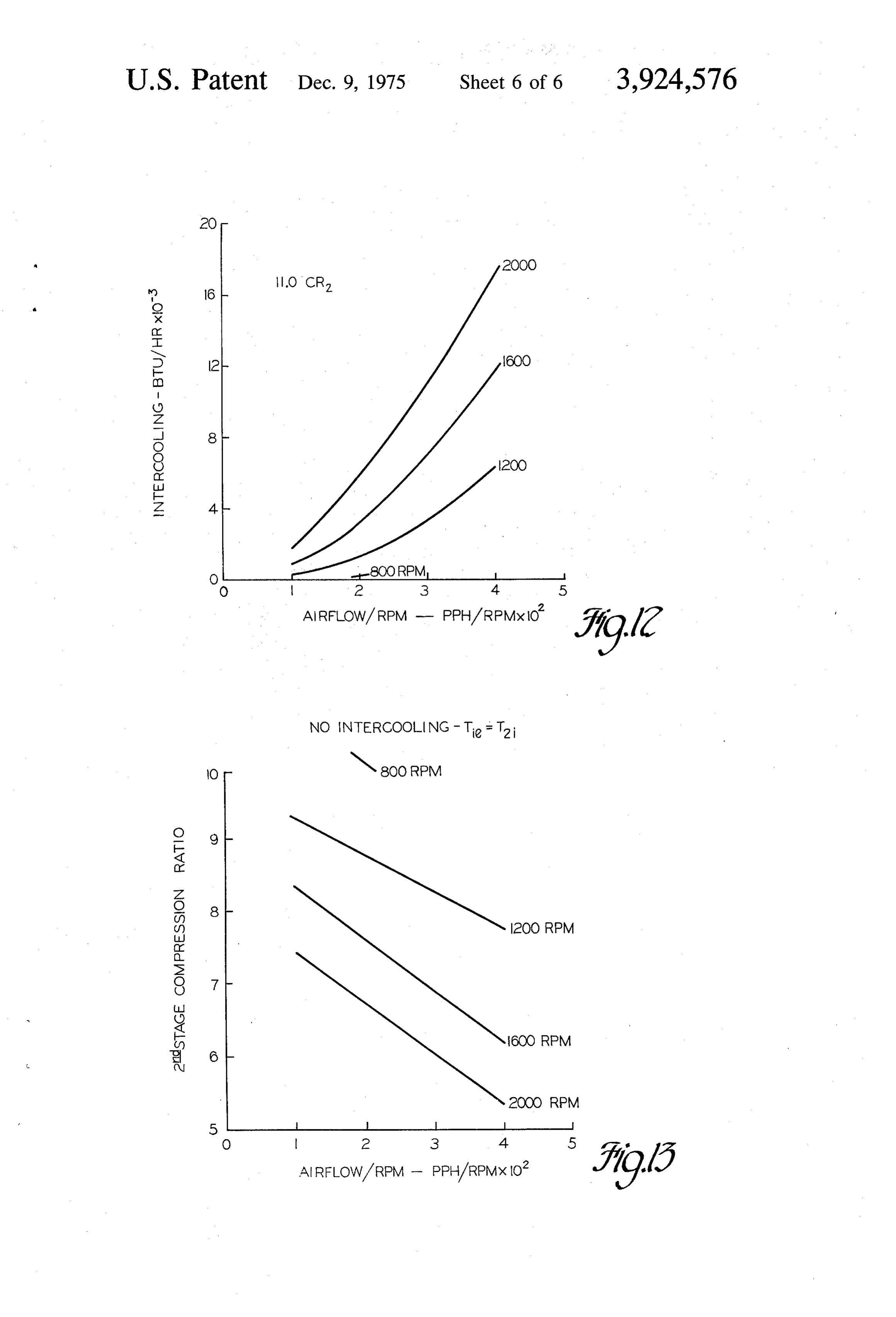
FIGS. 6 - 13 are graphs showing the relationships of exhausted from cylinder first stage combustion products are certain variables of staged combustion engine opera 12 on the upward exhaust tion determined or computed from the results of actual stroke of piston 14, passing through the heat exchanger 44 and intake conduit 43 to the second stage cylinder engine tests.
45 13 into which they are transferred by piston 15 moving
DESCRIPTION OF ILLUSTRATIVE downwardly on its intake stroke while piston 14 is mov EMBODIMENTS 'ing upwardly on its exhaust stroke. Air supplied
Referring first to FIG. 1 of the drawings, numeral 10 through pipe 45 mixes with the first stage combustion generally indicates a two-cylinder internal combustion plying theduring products second the interstage transfer step, thus sup stage cylinder with a mixture of com engine having a pair of cylinders 12, 13 containing 50 bustibles and air, preferably reciprocating pistons 14, 15, respectively, and defining metric ratio or slightly lean inoffuel approximately stoichio
therewith variable volume working and combustion overall air-fuel ratio and, in either case, heavily diluted chambers 16, 17, respectively. Pistons 14, 15 are re spectively connected by connecting rods 18, 19 to the with unburnables and having limited heat content in oppositely eccentric throws 20, 22 of a crankshaft 23. 55 The second stagebecause the combustibles of prior partial combustion.
mixture is then compressed on the
Cylinder 12 includes an inlet port 24 controlled by a upward compression stroke of piston 15 and is ignited poppet valve 25 and connecting with a source of air by autoignition at a point preferably near the end of the and fuel mixture, such as a carburetor or fuel injection compression stroke. Burning then takes place in which means, not shown, through an inlet conduit 27 having a the combustibles are almost completely burned but the throttle 28. Cylinder 12 also includes an exhaust or 60 combustion temperatures are relatively low so that outlet port 30 controlled by a poppet valve 32 and little or no additional oxides of nitrogen are formed. connecting with an outlet conduit 33. A spark plug 34 The downward expansion stroke of piston A5 follows, is also provided in the cylinder 12 to ignite combustible giving an output of additional work to the crankshaft fuel mixtures in the combustion chamber 16. 23 and the resulting combustion products are then Cylinder 13 includes inlet and exhaust ports 37, 38 65 exhausted through conduit 47 on the upward exhaust controlled respectively by an inlet poppet valve 40 and stroke of the piston 15. If desired, a portion of the first an exhaust poppet valve 42. Inlet port 37 connects stage exhaust gases may be recirculated to the first through an inlet conduit 43 and outlet conduit 33 with stage inlet through the recirculation conduit 48. the combustion chamber 16 of cylinder 14. A heat FIG. 2 illustrates graphically an exemplary record of exchanger 44 and an air admission pipe 45 are pro the pressure versus time events in an engine operating
Page 10
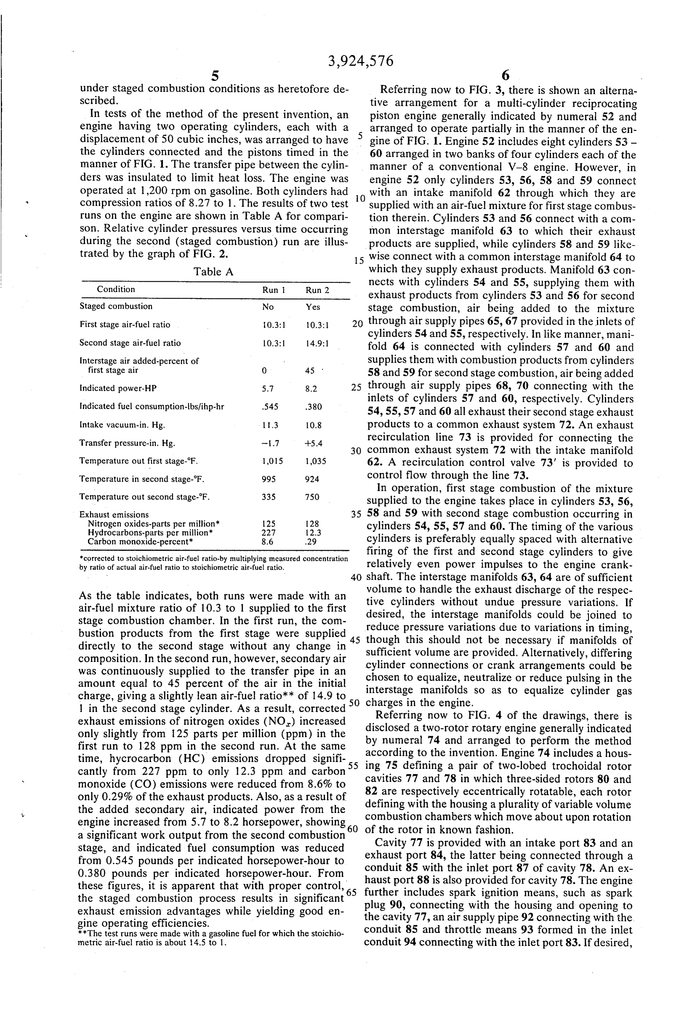
under staged combustion conditions as heretofore de Referring now to FIG. 3, there is shown an alterna scribed. tive arrangement for a multi-cylinder reciprocating In tests of the method of the present invention, an piston engine generally indicated by numeral 52 and engine having two operating cylinders, each with a arranged to operate partially in the manner of the en displacement of 50 cubic inches, was arranged to have gine of FIG. 1. Engine 52 includes eight cylinders 53 - the cylinders connected and the pistons timed in the 60 arranged in two banks of four cylinders each of the manner of FIG. 1. The transfer pipe between the cylin manner of a conventional V-8 engine. However, in ders was insulated to limit heat loss. The engine was engine 52 only cylinders 53, 56, 58 and 59 connect operated at 1,200 rpm on gasoline. Both cylinders had with an intake manifold 62 through which they are compression ratios of 8.27 to 1. The results of two test 10 supplied with an air-fuel mixture for first stage combus runs on the engine are shown in Table A for compari tion therein. Cylinders 53 and 56 connect with a com son. Relative cylinder pressures versus time occurring mon interstage manifold 63 to which their exhaust during the second (staged combustion) run are illus products are supplied, while cylinders 58 and 59 like trated by the graph of FIG. 2. 15 wise connect with a common interstage manifold 64 to Table A which they supply exhaust products. Manifold 63 con
Condition Run Ruin 2 nects with cylinders 54 and 55, supplying them with exhaust products from cylinders 53 and 56 for second
Staged combustion No Yes stage combustion, air being added to the mixture First stage air-fuel ratio 0.3:1 0.3:1 through air supply pipes 65, 67 provided in the inlets of Second stage air-fuel ratio 10.3: 14.9:1 cylinders 54 and 55, respectively. In like manner, mani fold 64 is connected with cylinders 57 and 60 and
Interstage air added-percent of supplies them with combustion products from cylinders first stage air 0 45 58 and 59 for second stage combustion, air being added Indicated power-HP 5.7 8.2 25 through air supply pipes 68, 70 connecting with the Indicated fuel consumption-lbs/ihp-hr 545 380 inlets of cylinders 57 and 60, respectively. Cylinders 54, 55, 57 and 60 all exhaust their second stage exhaust
Intake vacuum-in. Hg. 1.3 10.8 products to a common exhaust system 72. An exhaust Transfer pressure-in. Hg. -.7 --54 recirculation line 73 is provided for connecting the 30 common exhaust system 72 with the intake manifold
Temperature out first stage-F. 1,015 1,035 62. A recirculation control valve 73' is provided to Temperature in second stage-F. 995 924 control flow through the line 73. Temperature out second stage-F. 335 750
In operation, first stage combustion of the mixture supplied to the engine takes place in cylinders 53, 56,
Exhaust emissions 35 58 and 59 with second stage combustion occurring in Nitrogen oxides-parts per million* 125 128 cylinders 54, 55, 57 and 60. The timing of the various Hydrocarbons-parts per million* 227 12.3
Carbon monoxide-percent 8.6 29 cylinders is preferably equally spaced with alternative *corrected to stoichiometric air-fuel ratio-by multiplying mcasured concentration firing of the first and second stage cylinders to give by ratio of actual air-fuel ratio to stoichiometric air-fuel ratio. relatively even power impulses to the engine crank 40 shaft. The interstage manifolds 63, 64 are of sufficient
As the table indicates, both runs were made with an tive volume to handle the exhaust discharge of the respec air-fuel mixture ratio of 10.3 to 1 supplied to the first desired, cylinders without undue pressure variations. If stage combustion chamber. In the first run, the com reduce pressure the interstage manifolds could be joined to bustion products from the first stage were supplied 45 though this should variations due to variations in timing, directly to the second stage without any change in sufficient volume arenot be necessary if manifolds of provided. Alternatively, differing composition. In the second run, however, secondary air cylinder connections or crank arrangements could be was continuously supplied to the transfer pipe in an chosen to equalize, neutralize or reduce pulsing amount equal to 45 percent of the air in the initial interstage manifolds so as to equalize cylinderin gas the charge, giving a slightly lean air-fuel ratio of 14.9 to 50 charges in the engine.
1 in the second stage cylinder. As a result, corrected Referring now to FIG. 4 of the drawings, there is exhaust emissions of nitrogen oxides (NO) increased disclosed only slightly from 125 parts per million (ppm) in the by numerala two-rotor 74 and rotary engine generally indicated arranged to perform the method first run to 128 ppm in the second run. At the same according to the invention. Engine time, hycrocarbon (HC) emissions dropped signifi 55 ing 75 defining a pair of two-lobed74 trochoidal includes a hous cantly from 227 ppm to only 12.3 ppm and carbon cavities 77 and 78 in which three-sided rotors 80rotor and monoxide (CO) emissions were reduced from 8.6% to 82 are respectively eccentrically rotatable, each rotor only 0.29% of the exhaust products. Also, as a result of the added secondary air, indicated power from the defining with the housing a plurality of variable volume combustion chambers which move about upon rotation engine increased from 5.7 to 8.2 horsepower, showing 60 of the rotor in known fashion.
a significant work output from the second combustion Cavity 77 is provided with an intake port 83 and an stage, and indicated fuel consumption was reduced exhaust port 84, the latter being connected through a from 0.545 pounds per indicated horsepower-hour to conduit 85 with the inlet port 87 of cavity 78. An ex 0.380 pounds per indicated horsepower-hour. From haust port 88 is also provided for cavity 78. The engine these figures, it is apparent that with proper control, 5 further the staged combustion process results in significant plug 90, connecting withignition includes spark means, such as spark exhaust emission advantages while yielding good en the cavity 77, an air supplythe housing and opening to pipe 92 connecting with the gine operating efficiencies. conduit 85 and throttle means 93 formed in the inlet **The test runs were made with a gasoline fuel for which the stoichio metric air-fuel ratio is about 14.5 to 1. conduit 94 connecting with the inlet port 83. If desired,
Page 11
an interstage heat exchanger could also be provided as manifolds until the beginning of a later second stage could means for varying the second stage compression intake stroke. FIG. 5 shows the interstage phasing and ratio. combustion timing of the FIG. 3 arrangement. In operation, rotation of the engine rotors causes a In applying the staged combustion processes to a fuel-rich air-fuel mixture to be drawn into the cavity rotary engine, it is possible to connect two rotors in 77, where it is compressed, burned in a first stage of series so that the exhaust processes of the chambers combustion, and expanded with power output to the defined by the first stage rotor are coextensive with the rotor 80. The combustion products are then transferred intake processes of the chambers defined by the second through conduit 85 to the second stage cavity 78, addi 10 stage rotor. Alternatively, however, torsional vibrations tional air being added through pipe 92 during the trans may be reduced by arranging for equal firing intervals fer process. In cavity 78 the first stage combustion in the manner shown in FIG. 4, in which the two rotors products are again compressed and passed through a are oppositely timed. The effect of this arrangement on second stage of combustion, preferably initiated by the gas flow between chambers may be varied some autoignition. The gases are then expanded with power what by selection of the port locations and timing. output to rotor 82 and exhausted through port 88. 15 Operational Variables
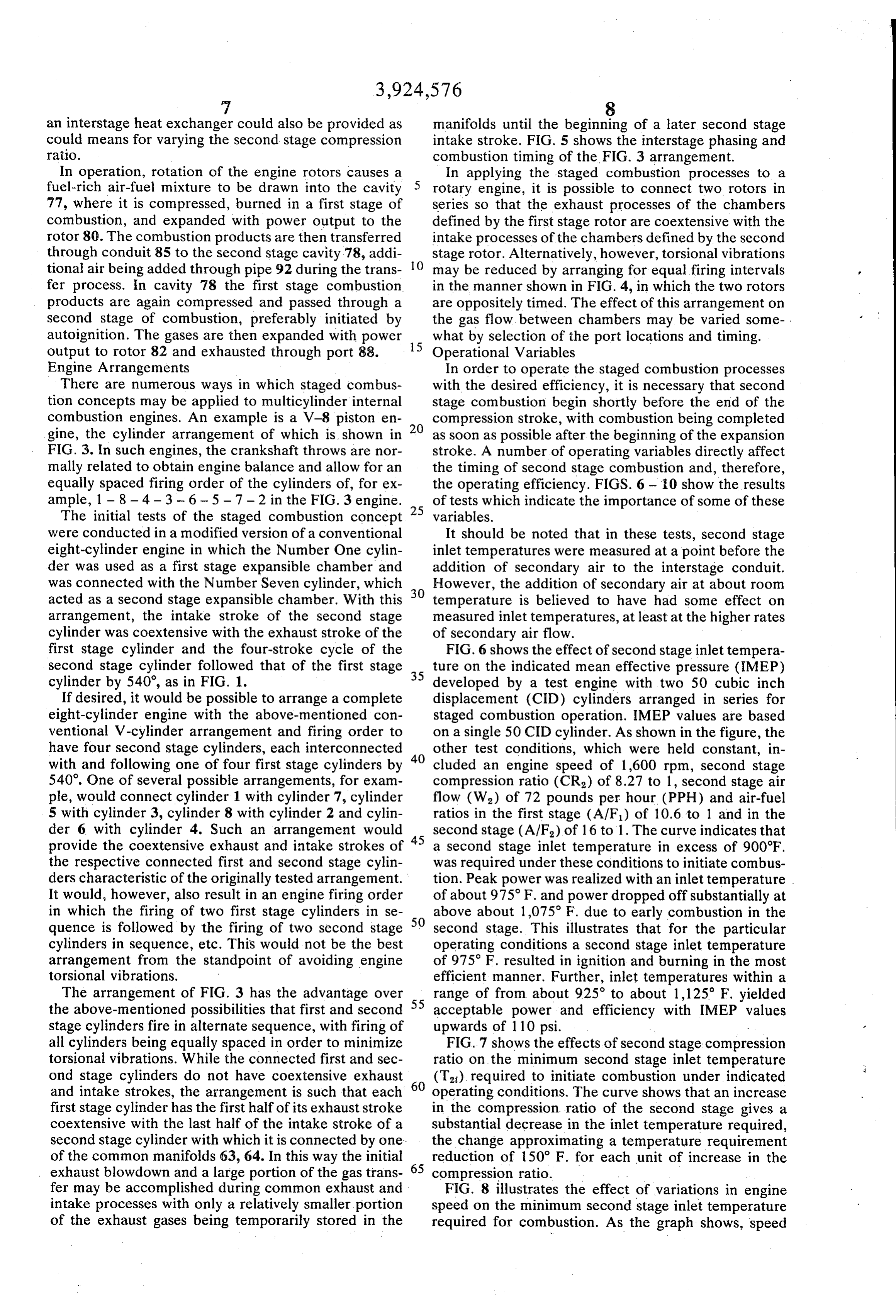
Engine Arrangements In order to operate the staged combustion processes There are numerous ways in which staged combus with the desired efficiency, it is necessary that second tion concepts may be applied to multicylinder internal stage combustion begin shortly before the end of the combustion engines. An example is a V-8 piston en compression stroke, with combustion being completed gine, the cylinder arrangement of which is shown in 20 as soon as possible after the beginning of the expansion FIG. 3. In such engines, the crankshaft throws are nor stroke. A number of operating variables directly affect mally related to obtain engine balance and allow for an the timing of second stage combustion and, therefore, equally spaced firing order of the cylinders of, for ex the operating efficiency. FIGS. 6-0 show the results ample, 1 - 8 - 4 - 3 - 6 - 5 - 7 - 2 in the FIG. 3 engine. 25 of tests which indicate the importance of some of these The initial tests of the staged combustion concept variables.
were conducted in a modified version of a conventional It should be noted that in these tests, second stage eight-cylinder engine in which the Number One cylin inlet temperatures were measured at a point before the der was used as a first stage expansible chamber and addition of secondary air to the interstage conduit. was connected with the Number Seven cylinder, which However, the addition of secondary air at about room acted as a second stage expansible chamber. With this 30 temperature is believed to have had some effect on arrangement, the intake stroke of the second stage measured inlet temperatures, at least at the higher rates cylinder was coextensive with the exhaust stroke of the of secondary air flow.
first stage cylinder and the four-stroke cycle of the FIG. 6 shows the effect of second stage inlet tempera second stage cylinder followed that of the first stage 35 ture on the indicated mean effective pressure (IMEP) cylinder by 540, as in FIG. 1. developed by a test engine with two 50 cubic inch If desired, it would be possible to arrange a complete displacement (CID) cylinders arranged in series for eight-cylinder engine with the above-mentioned con staged combustion operation. IMEP values are based ventional V-cylinder arrangement and firing order to on a single 50 CID cylinder. As shown in the figure, the have four second stage cylinders, each interconnected 40 other test conditions, which were held constant, in with and following one of four first stage cylinders by cluded an engine speed of 1,600 rpm, second stage 540. One of several possible arrangements, for exam compression ratio (CR) of 8.27 to 1, second stage air ple, would connect cylinder 1 with cylinder 7, cylinder flow (W) of 72 pounds per hour (PPH) and air-fuel 5 with cylinder 3, cylinder 8 with cylinder 2 and cylin ratios in the first stage (A/F) of 10.6 to 1 and in the der 6 with cylinder 4. Such an arrangement would 45 second stage (A/F) of 16 to 1. The curve indicates that provide the coextensive exhaust and intake strokes of a second stage inlet temperature in excess of 900°F. the respective connected first and second stage cylin was required under these conditions to initiate combus ders characteristic of the originally tested arrangement. tion. Peak power was realized with an inlet temperature It would, however, also result in an engine firing order of about 975 F. and power dropped off substantially at in which the firing of two first stage cylinders in se 50 above about 1,075 F. due to early combustion in the quence is followed by the firing of two second stage second stage. This illustrates that for the particular cylinders in sequence, etc. This would not be the best operating conditions a second stage inlet temperature arrangement from the standpoint of avoiding engine of 975 F. resulted in ignition and burning in the most torsional vibrations. efficient manner. Further, inlet temperatures within a The arrangement of FIG. 3 has the advantage over 55 range of from about 925 to about 1,125 F. yielded the above-mentioned possibilities that first and second acceptable power and efficiency with IMEP values stage cylinders fire in alternate sequence, with firing of upwards of 110 psi.
all cylinders being equally spaced in order to minimize FIG. 7 shows the effects of second stage compression torsional vibrations. While the connected first and sec ratio on the minimum second stage inlet temperature ond stage cylinders do not have coextensive exhaust 60 (T), required to initiate combustion under indicated and intake strokes, the arrangement is such that each operating conditions. The curve shows that an increase first stage cylinder has the first half of its exhaust stroke in the compression ratio of the second stage gives a coextensive with the last half of the intake stroke of a substantial decrease in the inlet temperature required, second stage cylinder with which it is connected by one. the change approximating a temperature requirement of the common manifolds 63, 64. In this way the initial reduction of 50 F. for each unit of increase in the exhaust blowdown and a large portion of the gas trans 65 compression ratio.
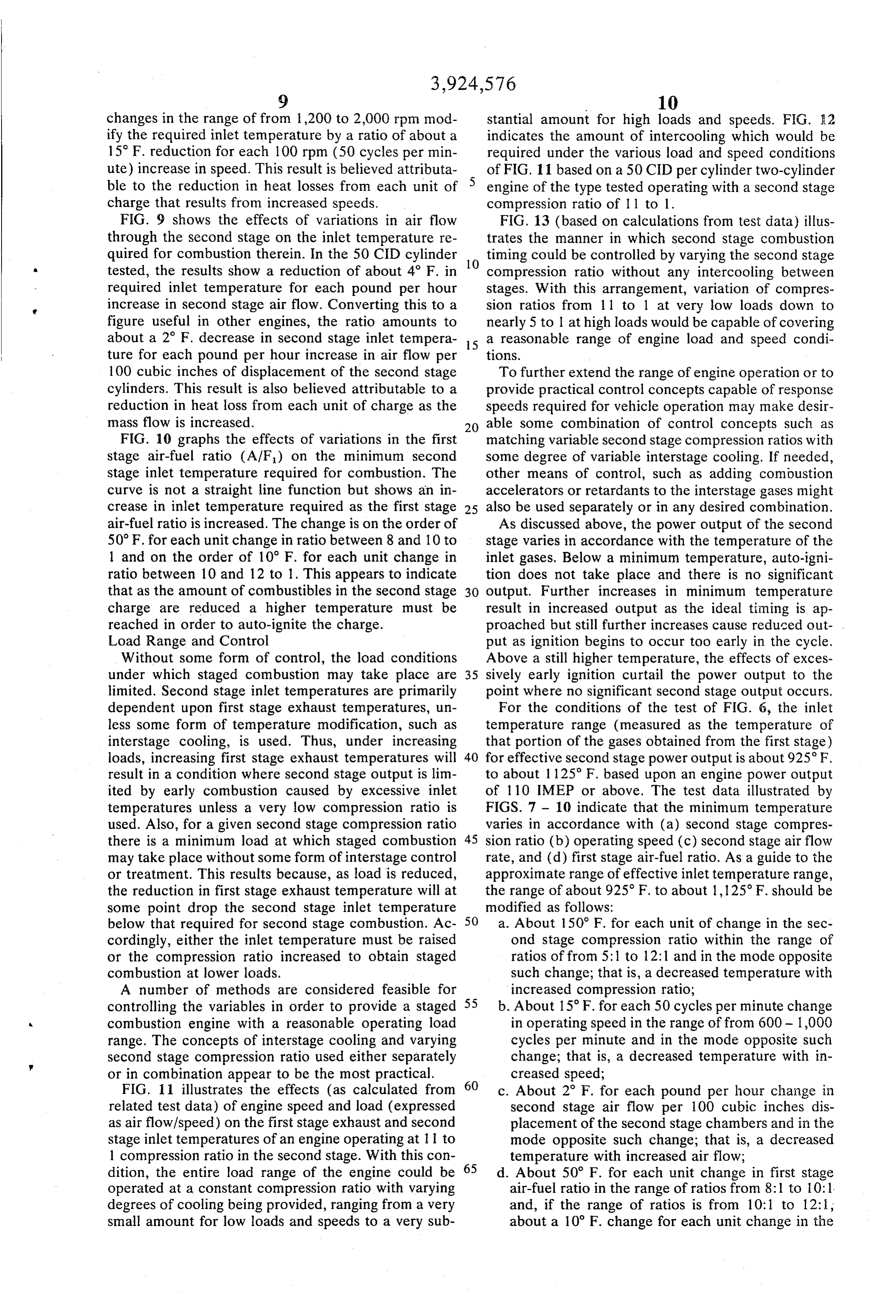
fer may be accomplished during common exhaust and FIG. 8 illustrates the effect of variations in engine intake processes with only a relatively smaller portion speed on the minimum second stage inlet temperature of the exhaust gases being temporarily stored in the required for combustion. As the graph shows, speed
Page 12
changes in the range of from 1,200 to 2,000 rpm mod stantial amount for high loads and speeds. FIG. A2 ify the required inlet temperature by a ratio of about a indicates the amount of intercooling which would be 15 F. reduction for each 100 rpm (50 cycles per min required under the various load and speed conditions ute) increase in speed. This result is believed attributa 5 of FIG. 11 based on a 50 CID per cylinder two-cylinder ble to the reduction in heat losses from each unit of engine of the type tested operating with a second stage charge that results from increased speeds. compression ratio of 11 to 1.
FIG. 9 shows the effects of variations in air flow FIG. 13 (based on calculations from test data) illus through the second stage on the inlet temperature re trates the manner in which second stage combustion quired for combustion therein. In the 50 CID cylinder 10 timing could be controlled by varying the second stage tested, the results show a reduction of about 4 F. in compression ratio without any intercooling between required inlet temperature for each pound per hour stages. With this arrangement, variation of compres increase in second stage air flow. Converting this to a sion ratios from 1 1 to 1 at very low loads down to figure useful in other engines, the ratio amounts to nearly 5 to 1 at high loads would be capable of covering about a 2 F. decrease in second stage inlet tempera 15 a reasonable range of engine load and speed condi ture for each pound per hour increase in air flow per tions.
100 cubic inches of displacement of the second stage To further extend the range of engine operation or to cylinders. This result is also believed attributable to a provide practical control concepts capable of response reduction in heat loss from each unit of charge as the speeds required for vehicle operation may make desir mass flow is increased. 20 able some combination of control concepts such as FIG. 10 graphs the effects of variations in the first matching variable second stage compression ratios with stage air-fuel ratio (AIF) on the minimum second some degree of variable interstage cooling. If needed, stage inlet temperature required for combustion. The other means of control, such as adding combustion curve is not a straight line function but shows an in accelerators or retardants to the interstage gases might crease in inlet temperature required as the first stage 25 also be used separately or in any desired combination. air-fuel ratio is increased. The change is on the order of As discussed above, the power output of the second 50 F. for each unit change in ratio between 8 and 10 to stage varies in accordance with the temperature of the 1 and on the order of 10 F. for each unit change in inlet gases, Below a minimum temperature, auto-igni ratio between 10 and 12 to 1. This appears to indicate tion does not take place and there is no significant that as the amount of combustibles in the second stage 30 output. Further increases in minimum temperature charge are reduced a higher temperature must be result in increased output as the ideal timing is ap reached in order to auto-ignite the charge. proached but still further increases cause reduced out Load Range and Control put as ignition begins to occur too early in the cycle. Without some form of control, the load conditions Above a still higher temperature, the effects of exces under which staged combustion may take place are 35 sively early ignition curtail the power output to the limited. Second stage inlet temperatures are primarily point where no significant second stage output occurs. dependent upon first stage exhaust temperatures, un For the conditions of the test of FIG. 6, the inlet less some form of temperature modification, such as temperature range (measured as the temperature of interstage cooling, is used. Thus, under increasing that portion of the gases obtained from the first stage) loads, increasing first stage exhaust temperatures will 40 for effective second stage power output is about 925 F, result in a condition where second stage output is lim to about 1125 F. based upon an engine power output ited by early combustion caused by excessive inlet of 110 IMEP or above. The test data illustrated by temperatures unless a very low compression ratio is FIGS. 7 – 10 indicate that the minimum temperature used. Also, for a given second stage compression ratio varies in accordance with (a) second stage compres there is a minimum load at which staged combustion 45 sion ratio (b) operating speed (c) second stage air flow may take place without some form of interstage control rate, and (d) first stage air-fuel ratio. As a guide to the or treatment. This results because, as load is reduced, approximate range of effective inlet temperature range, the reduction in first stage exhaust temperature will at the range of about 925 F. to about 1,125 F. should be some point drop the second stage inlet temperature modified as follows:
below that required for second stage combustion. Ac 50 a. About 150°F. for each unit of change in the sec cordingly, either the inlet temperature must be raised ond stage compression ratio within the range of or the compression ratio increased to obtain staged ratios of from 5:1 to 12:1 and in the mode opposite combustion at lower loads. such change; that is, a decreased temperature with A number of methods are considered feasible for increased compression ratio; controlling the variables in order to provide a staged 55 b. About 15 F. for each 50 cycles per minute change combustion engine with a reasonable operating load in operating speed in the range of from 600 - 1,000 range. The concepts of interstage cooling and varying cycles per minute and in the mode opposite such second stage compression ratio used either separately change; that is, a decreased temperature with in or in combination appear to be the most practical. 60 creased speed;
FIG. 11 illustrates the effects (as calculated from c. About 2 F. for each pound per hour change in related test data) of engine speed and load (expressed second stage air flow per 100 cubic inches dis as air flow/speed) on the first stage exhaust and second placement of the second stage chambers and in the stage inlet temperatures of an engine operating at l l to mode opposite such change; that is, a decreased 1 compression ratio in the second stage. With this con 65 temperature with increased air flow; dition, the entire load range of the engine could be d. About 50 F. for each unit change in first stage operated at a constant compression ratio with varying air-fuel ratio in the range of ratios from 8:l to 10:1. degrees of cooling being provided, ranging from a very and, if the range of ratios is from 10:1 to 12:1, small amount for low loads and speeds to a very sub about a 10 F. change for each unit change in the
Page 13
first stage air-fuel ratio, in the same mode as the It is believed that a 400 cubic inch displacement change; that is, increased temperature with in engine constructed in the arrangement of FIG. 3 and creased air-fuel ratio. using the staged combustion of the present invention The foregoing is a guide to the range of effective inlet would produce approximately equivalent maximum temperature to the second stage. In any specific engine, power to a 280 cubic inch displacement conventional it is necessary to select specific temperatures (or other engine. As compared with a conventional engine oper operating conditions if the temperature be fixed) to ating at a 10 to 1 air-fuel ratio, such as might be used to provide effective power output from the second stage reduce nitrogen oxides, the staged combustion engine desired.
Exhaust Emissions 10 is estimated to have about 30 percent lower indicated specific fuel consumption, about 23 percent lower
The engine of the present invention is characterized brake specific fuel consumption and to be capable of by combustion in the second stage largely of carbon obtaining about 23 percent greater miles per gallon in monoxide and hydrogen. In this respect, the combus equivalent vehicle operations.
tion differs from that of hydrocarbon fuel in the first 15 Reference is made herein to the overall engine air stage. Tests show that the quench volume of the com bustion chamber has a significant influence on carbon fuel ratio. By this is meant the relationship of the total monoxide emissions. This volume includes the piston tween the air to the engine (first stage air plus air admitted be stages) to the fuel admitted to the first stage.
cylinder crevice above the top compression ring and the volume between the top of the piston and the cylin 20 of the operating methodthatdescribed It should be apparent the various modifications may be adapted der head when the separation is less than 0.1 inch with through suitable modifications or additions to any of the piston at top dead center. Tests indicate that the the various engine arrangements described herein. carbon monoxide emissions are approximately propor tional to the second stage quench volume. While such toWhile the invention has been described by reference proportionality may not exist over the entire range of 25 stood that illustrative certain embodiments, it should be under possible quench volumes, it is desirable to minimize scope of the inventive conceptscould numerous changes be made within the disclosed. Accordingly, such volume in the second stage.
As to the first stage, its quench volume does not disclosureit is intended that the invention not be limited by the critically affect engine emissions. but that it have the full scope permitted by As to oxides of nitrogen, tests have indicated that 30 I claim: of the following claims.
the language very small percentages of NO are present in the first 1. The method of operating an internal combustion stage. Further, tests have shown that exhaust gas recir engine of the type having expansible chambers in which culation to the first stage further decreases the NO a compressed change is burned and expanded to supply emissions. With respect to the second stage, it is recog net energy per cycle to a rotating shaft, the method nized that making the first stage air-fuel ratio more lean 35 comprising the steps of:
reduces the second stage combustion temperature. a. successively compressing, burning and expanding a This makes NO formation in the second stage less mixture composed primarily of air and hydrocar likely and reduces overall engine NO emissions. bon fuel in combustion supporting proportions but Test measurements have been made using exhaust sufficiently gas recirculation to the first stage, utilizing the exhaust 40 produts having rich in fuel to produce combustion products of the second stage or of the first stage before low residuals of nitrogen oxides and the addition of air. Such tests indicate that NO pro high residuals of incompletely burned fuel combus duction of the engine decreases with increased recircu tibles primarily in the form of CO and H, while lation. The benefit is most pronounced when the delivering primary energy to the rotating shaft; amount of recirculation is less than about 20 percent by 45 b. adding air to said combustion products in amount volume of the first stage air flow. At about 20 percent sufficient to form a new mixture having (1) an exhaust gas recirculation or more, the effect of the overall engine air-fuel ratio slightly lean in fuel, (2) air-fuel ratio of the first stage was found to disappear. available total energy substantially less than that of With lesser amounts of recirculation, an increase of the hydrocarbon fuel originally supplied, and (3) a capability of compression ignition, and burnable to first stage air-fuel ratio from 10.9 to 11.6 substantially 50 minimize increased the nitrogen oxides. In tests with a two-cylin residuals of combustibles while maintain der engine operating at 2,000 rpm, wide-open throttle, ing low residuals of nitrogen oxides; and some exhaust gas recirculation to the first stage, c. compressing said last mixture sufficiently to initi together with cooling of the interstage gases in the ate combustion;
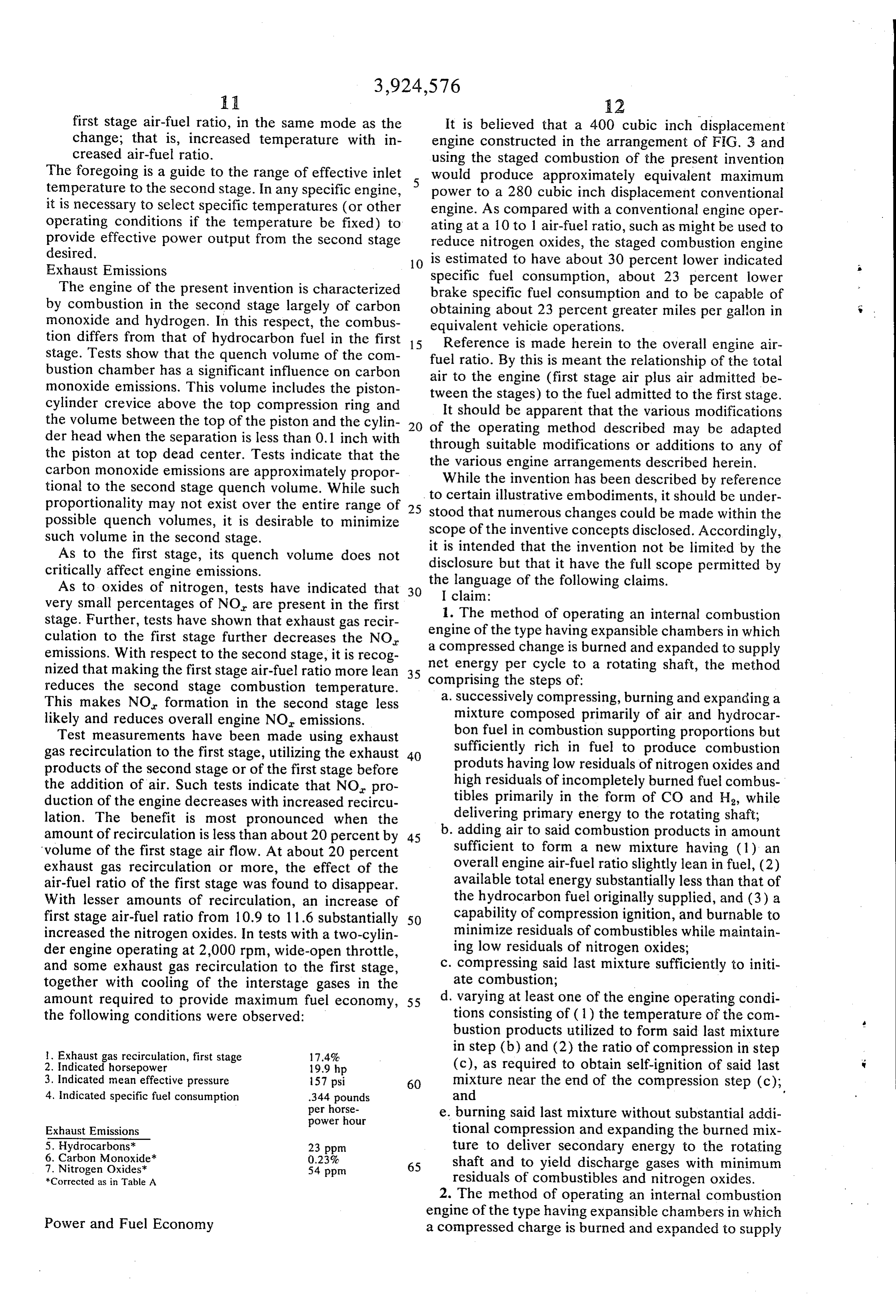
amount required to provide maximum fuel economy, 55 d. varying at least one of the engine operating condi the following conditions were observed: tions consisting of (1) the temperature of the com bustion products utilized to form said last mixture l. Exhaust gas recirculation, first stage 17.4% in step (b) and (2) the ratio of compression in step 2. Indicated horsepower 19.9 hp (c), as required to obtain self-ignition of said last 3. Indicated mean effective pressure 157 psi 60 mixture near the end of the compression step (c); 4. Indicated specific fuel consumption .344 pounds and per horse e. burning said last mixture without substantial addi power hour
Exhaust Emissions tional compression and expanding the burned mix
6. Carbon Monoxide 23 ppm
ture to deliver secondary energy to the rotating 7. Nitrogen Oxides" 54 ppm 65 shaft and to yield discharge gases with minimum *Corrected as in Table A residuals of combustibles and nitrogen oxides. 2. The method of operating an internal combustion engine of the type having expansible chambers in which
Power and Fuel Economy a compressed charge is burned and expanded to supply
Page 14
net energy per cycle to a rotating shaft, the method ergy to the rotating shaft while producing exhaust comprising the steps of: gases having low residuals of both nitrogen oxides a. Successively compressing, burning and expanding a and combustibles.
mixture composed primarily of (1) air and hydro 4. The method of operating an internal combustion carbon fuel in combustion supporting proportions' engine of the type having at least two expansible cham but substantially richer in fuel than a stoichiomet bers that execute successive expanding and contracting ric mixture, and (2) recirculuated combustion strokes and each supplies net energy per cycle to a products, to produce combustion products having rotating shaft, the method comprising the steps of: low residuals of nitrogen oxide and high residuals a. Successively supplying to one of said chambers a of incompletely burned fuel combustibles substan- 10 mixture composed primarily of air and hydrocar tially in the form of Hand CO, while delivering bon fuel in combustion supporting proportions primary energy to the rotating shaft; with an excess of fuel over stoichiometric so as to b. adding air to said combustion products in amount produce, upon combustion, gases having low resid sufficient to form a new mixture having (1) an 15 uals of nitrogen oxides and high residuals of com overall engine air-fuel ratio slightly lean in fuel, (2) bustibles primarily in the form of H and CO; available total energy substantially less than that of b. Successively compressing, burning, and expanding the hydrocarbon fuel originally supplied, and (3) a said mixtures in said one chamber to deliver pri capability of compression ignition, and burnable to mary energy to the rotating shaft and to produce minimize residuals of combustibles while maintain- 20 completelygases interstage having substantial amounts of in burned fuel but low in nitrogen oxides;
ing low residuals of nitrogen oxides; c. compressing c. varying the temperature of the interstage gases to said last mixture sufficient to initiate combustion; control said temperature within a desired range, d. varying at least one of the engine operating condi selected to assure self-ignition of the subsequently tions consisting of (1) the temperature of the com formed mixtures near the end of the second com bustion products utilized to form said last mixture 25 pression step (d);
in step (b) and (2) the ratio of compression in step d. successively deliverying said temperature con (c), as required to obtain self-ignition of said last trolled interstage gases to the other of said cham mixture near the end of the compression step (c); bers, together with air in amount sufficient to pro and e. burning said least mixture without substantial addi- 30 vide mixtures having (1) overall engine air-fuel tional compression and expanding the burned mix ratios leaner than stoichiometric, (2) available ture to deliver secondary energy to the rotating total energy substantially less than that of the hy drocarbon fuel originally supplied, and (3) a capa shaft and to yield combustion products with mini bility of compression ignition when compressed in mum residuals of combustibles and nitrogen ox a predetermined compression ratio; ides; said recirculated combustion products being 35 e. compressing said successive last mixture in said from one of said expansion steps. predetermined ratio in said other chamber so as to 3. The method of operating an internal combustion cause self-ignition of said mixtures near the end of engine of the type having at least two expansible cham such compression step; and bers that execute successive expanding and contracting f, successively burning and expanding the mixtures in strokes and each supplies net energy per cycle to a 40 the last mentioned chamber without substantial rotating shaft, the method comprising the steps of: additional compression to deliver secondary en a. successively supplying to one of said chambers a ergy to the rotating shaft while producing exhaust mixture composed primarily of air and hydrocar gases having low residuals of both nitrogen oxides bon fuel in combustion supporting proportions and combustibles.
with an excess of fuel over stoichiometric so as to 45 produce, upon combustion, gases having low resid 5. The method of operating an internal combustion uals of nitrogen oxides and high residuals of com engine of the type having at least two expansible cham bustibles primarily in the form of H, and CO; bers that execute successive expanding and contracting b. successively compressing, burning, and expanding strokes and each supplies net energy per cycle to a said mixtures in said one chamber to deliver pri- 50 rotating shaft, the method comprising the steps of: mary energy to the rotating shaft to produce inter a. Successively supplying to one of said chambers a stage gases having substantial amounts of incom mixture composed primiarly of air and hydrocar pletely burned fuel but low in nitrogenn oxides; bon fuel in combustion supporting proportions c. successively delivering said interstage gases to the with an excess of fuel over stoichiometric so as to other of said chambers, together with air in amount 55 produce, upon combustion, gases having low resid sufficient to provide mixtures having (1) overall uals of nitrogen oxides and high residuals of com engine air-fuel ratios leaner than stoichiometric, bustibles primarily in the form of H and CO; (2) available total energy substantially less than b. Successively compressing, burning, and expanding that of the hydrocarbon fuel originally supplied, said mixtures in said one chamber to deliver pri and (3) a capability of compression ignition; 60 mary energy to the rotating shaft and to produce d. compressing said successive last mixtures in said interstage gases having substantial amounts of in other chamber sufficiently to initiate combustion, completely burned fuel but low in nitrogen oxides; the ratio of such compression being variable to c. Controlling the temperatures of the interstage asssure self-ignition of said last mixtures near the gases before the addition of air thereto within the end of the second compression step (d); and 65 temperature range from about 925° F to 1,125 F e, successively burning and expanding the mixtures in when the engine is operating at a speed of about the last mentioned chamber without substantial 800 cycles of each chamber per minute and at a additional compression to deliver secondary en load of about 144 pounds per hour of air flow for
Page 15
each 100 cubic inches of displacement of the sec a pair of banks each having four aligned cylinders, ond stage engine chambers with a second stage pistons reciprocable within said cylinders, respec compression ratio of about 8.25 to 1, a first stage tively, a crankshaft, and connecting rods connect air-fuel ratio of about 10.5 to 1 and an overall ing the pistons of each bank, respectively, to the air-fuel ratio of about 16 to 1 and varying said crankshaft, the two inboard cylinders of one bank temperature range for other operating conditions together with the two outboard cylinders of the as follows: opposite bank comprising first stage cylinders and 1. about 150°F for each unit of change in the sec the two inboard cylinders of said opposite bank ond stage compression ratio within the range of O together with the two outboard cylinders of said ratios of from 5:1 to 12:1 and in the mode oppo one bank comprising second stage cylinders, said site such change; cylinders being subject to operating cycles includ 2. about 15° F for each 50 cycles per minute ing intake, compression, expansion and exhaust change in operating speed in the range of from events produced by corresponding strokes of their 600 - 1,000 cycles per minute and in the mode 15 respective pistons, the cycles of all said cylinders opposite such change; being equally spaced and the first stage cylinders 3. about 2 F for each pound per hour change in and the second stage cylinders having alternate second stage air flow per 100 cubic inches dis expansion events, said cylinder cycles being phased placement of the second stage chambers and in such that the exhaust event of each first stage cylin the mode opposite such change; der occurs, at least in part, during the intake event 4. about 50 F for each unit change in first stage of a second stage cylinder in the same bank; air-fuel ratio in the range of ratios from 8:1 to an intake manifold and fuel supply system effective 10:1 and a change of about 10°F for each unit to supply said first stage cylinders with a fuel-rich change in first stage air-fuel ratio in the range of air-fuel mixture capable of producing upon com ratios from 10:1 to 12:1 and in the same mode as 25 bustion, discharge gases having substantial such change in each instance; amounts of incompletely burned fuel residuals and d. Successively delivering said interstage gases to the minimal quantities of nitrogen oxides; other of said chambers, together with air in amount spark ignition means for said first stage cylinders; sufficient to provide mixtures having (1) overall an interstage manifold for each bank and intercon engine air-fuel ratios leaner than stoichiometric, necting the first and second stage cylinders of their (2) available total energy substantially less than respective banks, said interstage manifolds being that of the hydrocarbon fuel originally supplied, connected to receive discharge gases exhausted and (3) a capability of compression ignition; from their respective first stage cylinders and to e. compressing said successive last mixtures in said supply said gases to their respective second stage other chamber sufficiently to initiate combustion; 35 cylinders;
and a. successively supplying to one of said chambers a f, successively burning and expanding the mixtures in mixture composed primarily of air and hydrocar the last mentioned chamber without substantial bon fuel in combustion supporting proportions additional compression to deliver secondary en with an excess of fuel over stoichiometric so as to ergy to the rotating shaft while producing exhaust 40 produce, upon combustion, gases having low resid gases having low residuals of both nitrogen oxides uals of nitrogen oxides and high residuals of com and combustibles. bustibles primarily in the form of H and CO; d. varying at least one of the engine operating condi means to supply air to said interstage manifolds, re tions consisting of (1) the temperature of the com spectively, in quantities sufficient to provide over bustion products utilized to form said last mixture 45 all engine operation leaner than stoichiometric; in step (b) and (2) the ratio of compression in step exhaust conduits for second stage cylinders of each (c), as required to obtain self-ignition of said last bank; and mixture near the end of the compression step (c); means to control the admission and discharge of and gases from the cylinders, respectively. 6. An internal combustion engine comprising, in 50 combination; * k + k is
Page 16
UNITED STATES PATENT AND TRADEMARK OFFICE
CERTIFICATE OF CORRECTION
INVENTOR(S) : Robert M. Siewert
It is Certified that error appears in the above-identified patent and that said Letters Patent are hereby Corrected as shown below:
Column 4, line 52, "ratio" should read --ratio) --. Column 13, line 22, "sufficient" should read
line 30, "least" should read --last--.
line 51, "shaft to" should read --shaft and to--.
line 53, "nitrogenn" should read
Column 15, lines 43-49, beginning "d varying at least one" and ending "compression step (c) ; and", should be deleted.
Column 16, lines 36-42, beginning "a successively supplying to one" and ending "form of H2 and CO; " should be deleted.
Signed and Sealed this
SEAL Sixth Day of July 1976 Attest.
RUTH C. MASON
Attesting Officer C. MARSHALL D ANN Commissioner of Patents and Trademarks

Provenance
- Collection
- Cited prior art
- Original PDF
- patentimages.storage.googleapis.com →
- Filed
- 1972-08-21
- Pages
- 16
- Method
- pdftotext (the PDF's own text layer) + pdftoppm 300dpi page scans
- Source
- Google Patents bibliographic record
- Granted
- 1975-12-09
- Inventors
- Robert M Siewert; General Motors Corp
- Transcribed from
- patentimages.storage.googleapis.com →