patent · US4520763
Fuel injection system
4 June 1985
Page 1 — bibliographic record
United States Patent (19) 11 Patent Number: 4,520,763 Lynch et al. 45) Date of Patent: Jun. 4, 1985 54 FUEL INJECTION SYSTEM 3,662,721 5/1972 Klein ................................... 123/462 75 Inventors: Franklin E. Lynch, Conifer; 4,015,569 4/1977 Leshner et al. ..................... 123/447 4,018, 190 4/1977 Henault ......... 123/DIG. 12
Nathaniel R. Baker, Denver, both of 4,103,653 8/1978 Ueno et al. .......................... 123/408 Colo. 4,167,920 9/1979 Lepera et al. ..... ... 123/DIG. 12 (73) Assignee: Ergenics Inc., Wyckoff, N.J. 4,178,882 12/1979 Anderson et al. ... 123/DIG. 12
(21) Appl. No.: 617,713 4,378,775 4/1983 Straubel et al. ..................... 123/458 22 Filed: Jun. 6, 1984 Primary Examiner-E. Rollins Cross
Attorney, Agent, or Firm-Charles E. Baxley
Related U.S. Application Data (63) Continuation of Ser. No. 305,409, Sep. 25, 1981, aban (57) ABSTRACT doned. Discloses a fuel injection system for the timed introduc (51) Int. Cl. .............................................. F02D 21/02 tion of a gaseous fuel such as hydrogen gas into a com 52 U.S. C. .... ... 123/1 A; 123/DIG. 12; bustion volume of an internal combustion engine. The 123/408; 123/447; 123/462; 123/527 system comprises (a) a chamber of fixed volume into 58) Field of Search .............. 123/447, DIG. 12, 1 A, which, at one time, gas flows from a fuel source and out 123/3, 525, 527, 446, 462, 406, 408 of which, at another time, gas flows to a combustion 56) References Cited volume of an internal combustion engine and (b) means for varying the pressure of the gas flowing to the cham
3,587,547 6/1971 Hussey ................................ 123/447 22 Claims, 6 Drawing Figures
H2 SOURCE
Page 2
Drawing sheet — no readable text.
Page 3
Drawing sheet — no readable text.
Page 4
Drawing sheet — no readable text.
Page 5
FUEL INJECTION SYSTEM BRIEF DESCRIPTION OF THE DRAWINGS
The objects and advantages of the present invention
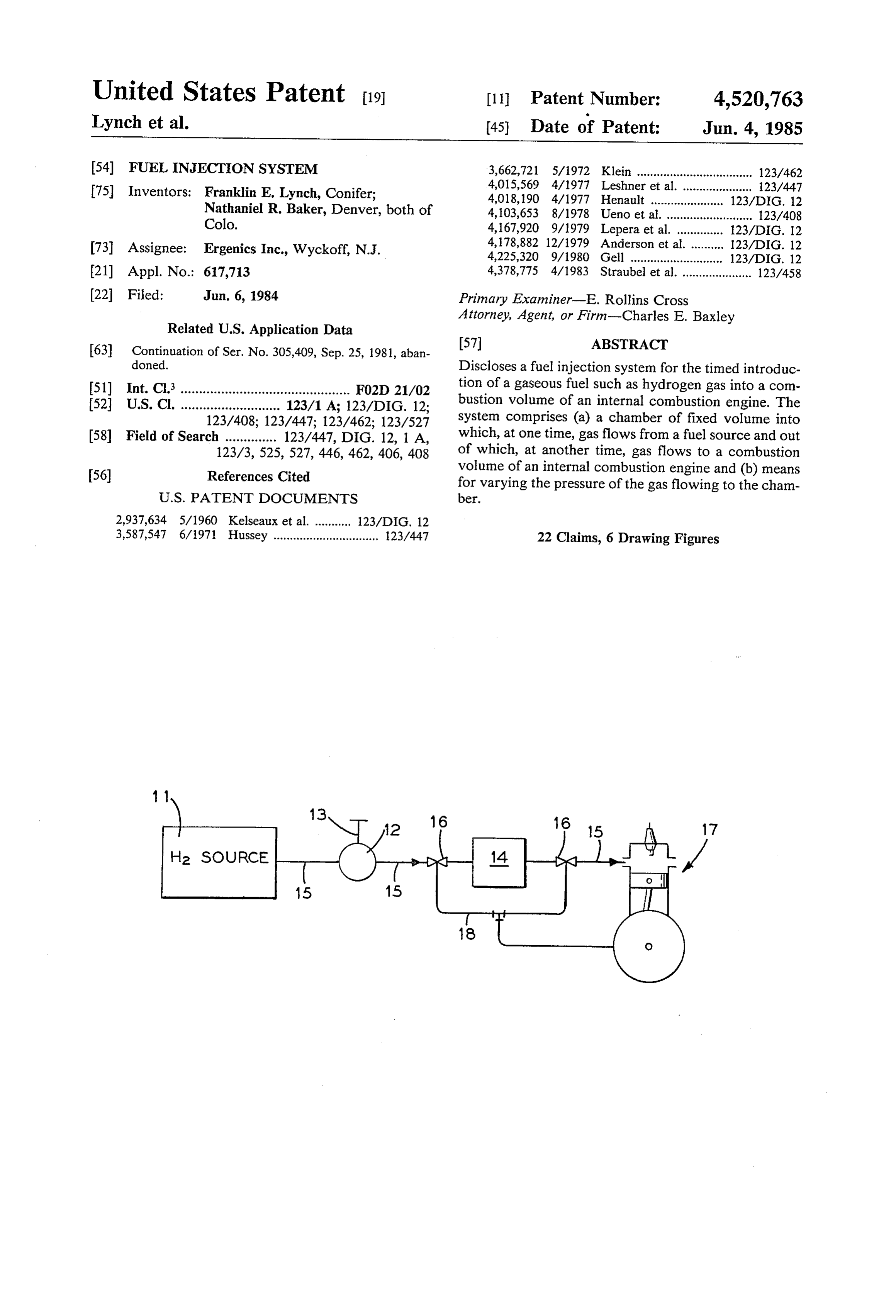
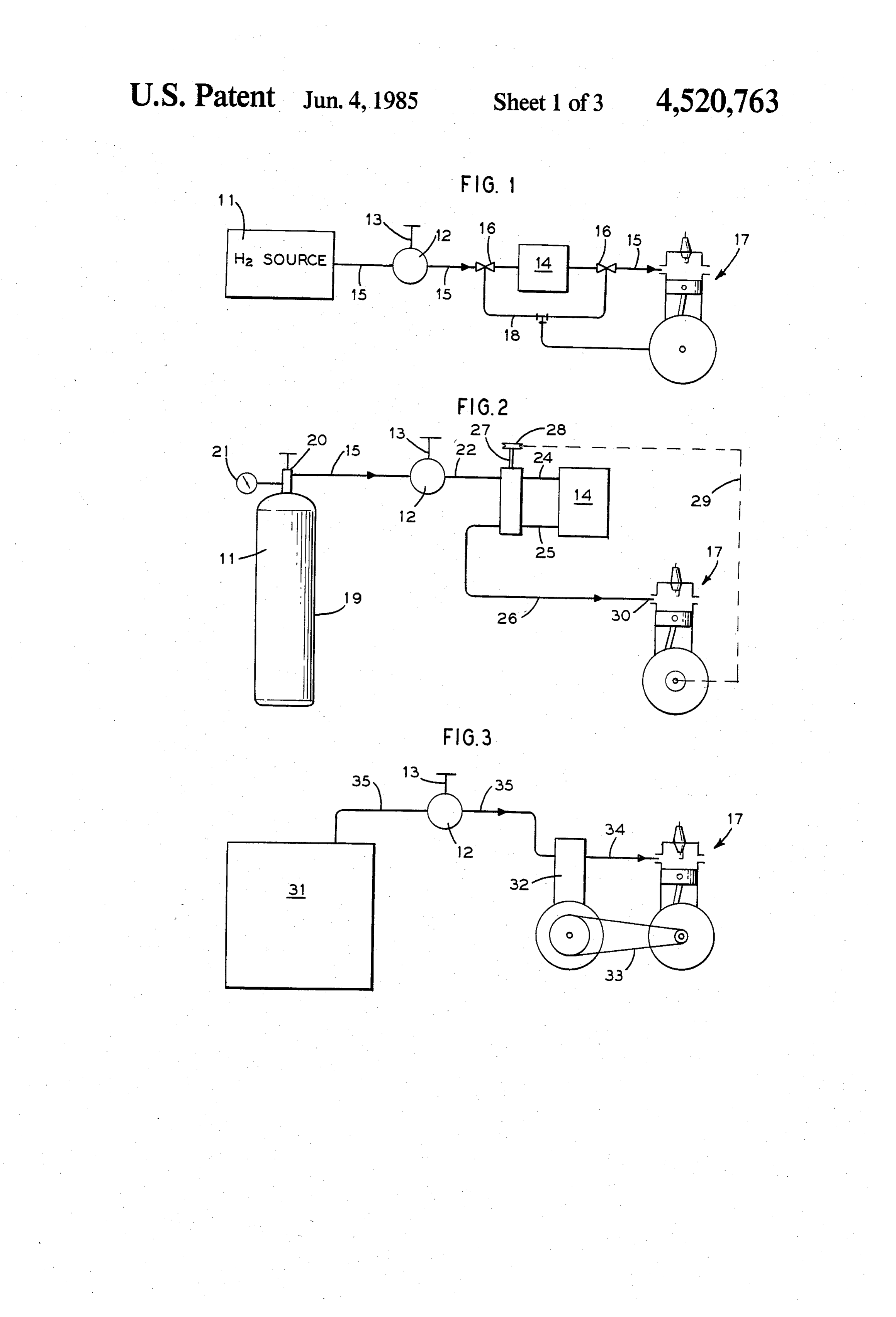
This is a continuation of co-pending application Ser. will become apparent from the following description No. 305,409 filed on Sept. 25, 1981 now abandoned. 5 taken in conjunction with the drawing in which: The present invention is concerned with gaseous fuel FIG. 1 is a diagramatical sketch of the elements of the injection into internal combustion engines and in partic invention as associated with a fuel supply means and an ular with gaseous hydrogen injection into internal com ICE.
bustion engines. FIG. 2 depicts the system of the present invention as 10 applied to a single cylinder, four stroke, Otto cycle ICE
BACKGROUND OF THE ART AND PROBLEM wherein hydrogen gas fuel is supplied from a high pres There are numerous disclosures in the art as to the Sue SOUCe.
desirability of fueling an internal combustion engine FIG. 3 depicts the system of the present invention as (ICE) with hydrogen. Not the least among the advan 5 applied to a single cylinder, four stroke, Otto cycle ICE tages envisioned by the art is that a hydrogen fueled Sue wherein hydrogen gas fuel is supplied from a low pres SOurce.
ICE should produce only water as an exhaust product
FIG.
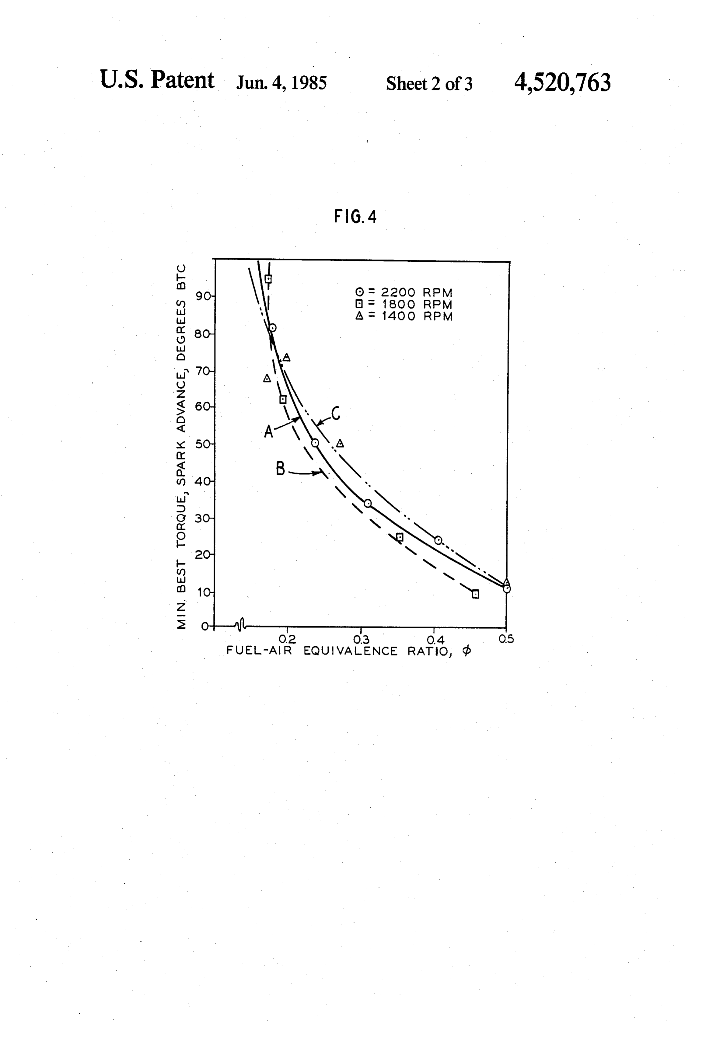
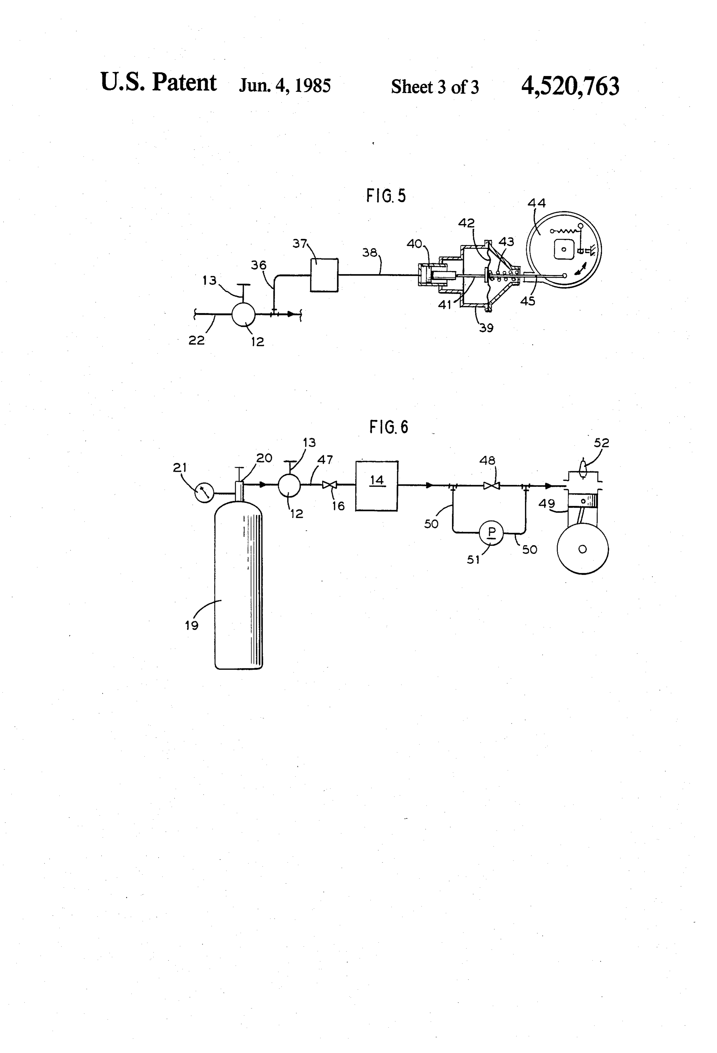
rather than the water-carbon oxide exhaust products of ship of ignition4 is an illustrative graph showing the relation engines fueled by hydrocarbons. The absence of carbon an timing and fuel/air equivalence ratio for Otto oxides especially carbon monoxide from exhaust gases 20 conditions. cycle engine operating under certain, specified is very important in instances where the ICE is em FIG. 5 illustrates a spark timing adjusting means ployed in closed-off spaces such as in mines. Buildup of useful in the practice of the present invention. carbon monoxide in mine atmospheres is exceedingly dangerous and is the subject of mine safety regulation. applied 6todepicts
FIG.
the system of the present invention as single cylinder two stroke, Diesel cycle
Where ICE's fueled by hydrocarbons are employed in 25 engine.
mines, it is mandatory that excess ventilation be pro vided so as to prevent exhaust fume buildup. Such ex GENERAL OBJECT AND DESCRIPTION OF cess ventilation is costly not only in capital equipment THE INVENTION but also in operation and maintenance. In addition to It is an object of the present invention to provide a usage in mines and other enclosed spaces, it is envi 30 means of hydrogen gas injection into an ICE which sioned that hydrogen-fueled ICE's may find uses based means will be inexpensive and effective. upon the premise that hydrocarbon fuels are becoming This object of the invention is attained through a fuel scarce and more expensive. For example, it is contem injection system for an ICE coupleable to a source of plated that hydrogen can become an economically and gaseous hydrogen comprising a means for controlling environmentally acceptable fuel for urban busses and 35 pressure, a means to selectively vary pressure control autos, fork-lift trucks and other vehicles used in circum means, a chamber into which fuel gas, e.g. hydrogen gas stances where exhaust fumes are a problem. of controlled pressure can flow from said means for Fueling an ICE with hydrogen presents problems. controlling pressure, means for permitting gas flow Substantial testing has revealed that hydrogen cannot between said means for controlling pressure and said be reliably introduced into an ICE by carburetion, that 40 chamber and said chamber and a combustion volume of is by premixing air or other oxidizer and hydrogen and the ICE, and means, for example, valve means, timed to introducing the mixture into the combustion volume or said ICE, whereby during a fuel admission event of the volumes (e.g. cylinder or cylinders) of an ICE. Even if combustion volume of the engine, flow of fuel gas from a carbureting device is employed to provide a properly the chamber to a combustion volume of the engine is stoichiometrically lean, hydrogen to air mixture, occa 45 permitted and flow from said means for controlling sional instances of prefiring in the carburetor occur. the pressure to said chamber is prohibited and whereby in Prior known fuel injection systems proposed for hydro absence of a fuel intake event of the combustion gen fueling of ICE's are sometimes of complicated and volume of the engine, flow of hydrogen is permitted expensive design and/or rely upon precise, difficultly 50 from said means for controlling pressure to said cham maintainable valve settings to deliver controllable ber and prohibited from said chamber to said combus amounts of hydrogen to combustion volumes so as to tionForvolume of the ICE.
provide adequate operator control of the ICE. Some of and purposes of generalized description, the elements associated with the invention are illustrated in prior systems, in effect, require an operator with an FIG. 1 of the drawing.
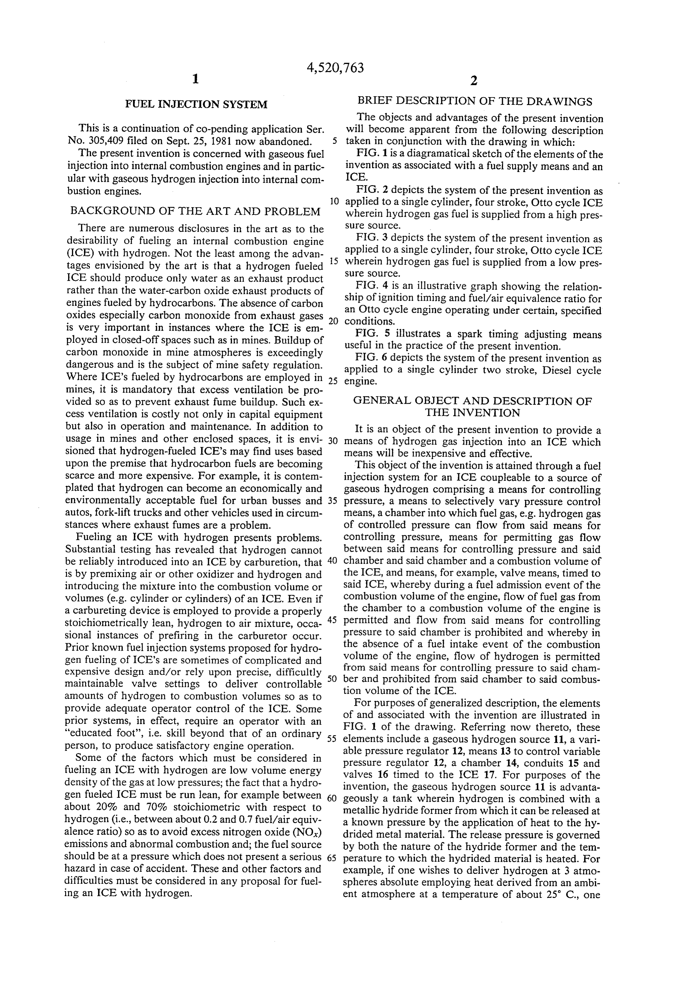
"educated foot', i.e. skill beyond that of an ordinary 55 elements include a gaseousReferring hydrogen now thereto, these source 11, a vari person, to produce satisfactory engine operation. able pressure regulator 12, means 13 to control variable Some of the factors which must be considered in fueling an ICE with hydrogen are low volume energy pressure regulator 12, a chamber 14, conduits 15 and density of the gas at low pressures; the fact that a hydro invention, timed valves 16 to the ICE 17. For purposes of the the gaseous hydrogen source 11 is advanta gen fueled ICE must be run lean, for example between 60 geously a tank wherein hydrogen is combined with a about 20% and 70% stoichiometric with respect to metallic hydride former from which it can be released at hydrogen (i.e., between about 0.2 and 0.7 fuel/air equiv a known pressure by the application of heat to the hy alence ratio) so as to avoid excess nitrogen oxide (NOx) drided metal material. The release pressure is governed emissions and abnormal combustion and; the fuel source by both the nature of the hydride former and the tem should be at a pressure which does not present a serious 65 perature to which the hydrided material is heated. For hazard in case of accident. These and other factors and example, if one wishes to deliver hydrogen at 3 atmo difficulties must be considered in any proposal for fuel spheres absolute employing heat derived from an ambi ing an ICE with hydrogen. ent atmosphere at a temperature of about 25 C., one
Page 6
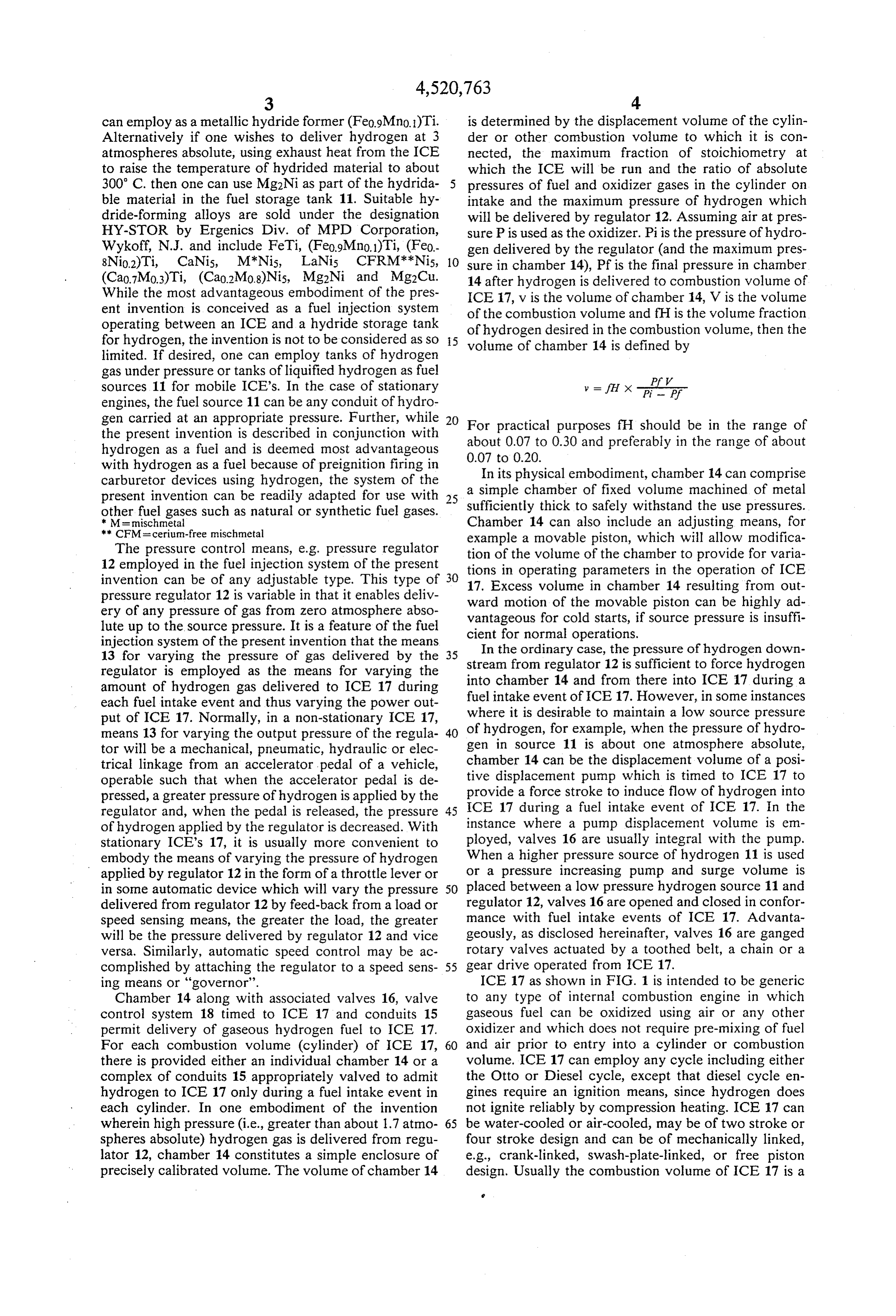
can employ as a metallic hydride former (Fe0.9Mino.)Ti. is determined by the displacement volume of the cylin Alternatively if one wishes to deliver hydrogen at 3 der or other combustion volume to which it is con atmospheres absolute, using exhaust heat from the ICE nected, the maximum fraction of stoichiometry at to raise the temperature of hydrided material to about which the ICE will be run and the ratio of absolute 300 C. then one can use Mg2Ni as part of the hydrida pressures of fuel and oxidizer gases in the cylinder on ble material in the fuel storage tank 11. Suitable hy intake and the maximum pressure of hydrogen which dride-forming alloys are sold under the designation will be delivered by regulator 12. Assuming air at pres HY-STOR by Ergenics Div. of MPD Corporation, sure P is used as the oxidizer. Pi is the pressure of hydro Wykoff, N.J. and include FeTi, (Fe0.9Mno.1)Ti, (Feo gen delivered by the regulator (and the maximum pres 8Nio.2)Ti, CaNis, M*Nis, LaNis CFRM**Nis, 10 sure in chamber 14), Pf is the final pressure in chamber (Cao.7Mo.3)Ti, (Cao.2Mo.8)Nis, Mg2Ni and Mg2Cu. 14 after hydrogen is delivered to combustion volume of While the most advantageous embodiment of the pres ICE 17, v is the volume of chamber 14, V is the volume ent invention is conceived as a fuel injection system of the combustion volume and f is the volume fraction operating between an ICE and a hydride storage tank of hydrogen desired in the combustion volume, then the for hydrogen, the invention is not to be considered as So 5 volume of chamber 14 is defined by limited. If desired, one can employ tanks of hydrogen gas under pressure or tanks of liquified hydrogen as fuel PA 7 sources 11 for mobile ICE's. In the case of stationary engines, the fuel source 11 can be any conduit of hydro y = H x off gen carried at an appropriate pressure. Further, while 20 For practical purposes fH should be in the range of the present invention is described in conjunction with about 0.07 to 0.30 and preferably in the range of about hydrogen as a fuel and is deemed most advantageous with hydrogen as a fuel because of preignition firing in 0.07In to its
physical embodiment, chamber 14 can comprise carburetor devices using hydrogen, the system of the present invention can be readily adapted for use with 25 sufficientlychamber a simple of fixed volume machined of metal thick to safely withstand the use pressures.
other fuel gases such as natural or synthetic fuel gases.
** CFMulcerium-free mischmetal
Chamber 14 can also include an adjusting means, for
The pressure control means, e.g. pressure regulator example a movable piston, which will allow modifica 12 employed in the fuel injection system of the present tion of the volume of the chamber to provide for varia invention can be of any adjustable type. This type of 30 tions
in operating parameters in the operation of ICE
Excess volume in chamber 14 resulting from out pressure regulator 12 is variable in that it enables deliv ery of any pressure of gas from zero atmosphere abso ward motion of the movable piston can be highly ad lute up to the source pressure. It is a feature of the fuel vantageous for cold starts, if source pressure is insuffi injection system of the present invention that the means cient for normal operations.
In the ordinary case, the pressure of hydrogen down 13 for varying the pressure of gas delivered by the 35 stream from regulator 12 is sufficient to force hydrogen regulator is employed as the means for varying the amount of hydrogen gas delivered to ICE 17 during into chamber 14 and from there into ICE 17 during a each fuel intake event and thus varying the power out fuel intake event of ICE 17. However, in Some instances put of ICE 17. Normally, in a non-stationary ICE 17, where it is desirable to maintain a low source pressure means 13 for varying the output pressure of the regula 40 of hydrogen, for example, when the pressure of hydro tor will be a mechanical, pneumatic, hydraulic or elec gen in source 11 is about one atmosphere absolute, trical linkage from an accelerator pedal of a vehicle, chamber 14 can be the displacement volume of a posi operable such that when the accelerator pedal is de tive displacement pump which is timed to ICE 17 to pressed, a greater pressure of hydrogen is applied by the provide a force stroke to induce flow of hydrogen into regulator and, when the pedal is released, the pressure 45 ICE 17 during a fuel intake event of ICE 17. In the of hydrogen applied by the regulator is decreased. With instance where a pump displacement volume is em stationary ICE's 17, it is usually more convenient to ployed, valves 16 are usually integral with the pump. embody the means of varying the pressure of hydrogen When a higher pressure source of hydrogen 11 is used applied by regulator 12 in the form of a throttle lever or or a pressure increasing pump and surge Volume is in some automatic device which will vary the pressure placed between a low pressure hydrogen source 11 and delivered from regulator 12 by feed-back from a load or regulator 12, valves 16 are opened and closed in confor speed sensing means, the greater the load, the greater mance with fuel intake events of ICE 17. Advanta will be the pressure delivered by regulator 12 and vice geously, as disclosed hereinafter, valves 16 are ganged versa. Similarly, automatic speed control may be ac rotary valves actuated by a toothed belt, a chain or a complished by attaching the regulator to a speed sens 55 gear drive operated from ICE 17. ing means or "governor'. ICE 17 as shown in FIG. 1 is intended to be generic Chamber 14 along with associated valves 16, valve to any type of internal combustion engine in which control system 18 timed to ICE 17 and conduits 15 gaseous fuel can be oxidized using air or any other permit delivery of gaseous hydrogen fuel to ICE 17. oxidizer and which does not require pre-mixing of fuel For each combustion volume (cylinder) of ICE 17, 60 and air prior to entry into a cylinder or combustion there is provided either an individual chamber 14 or a volume. ICE 17 can employ any cycle including either complex of conduits 15 appropriately valved to admit the Otto or Diesel cycle, except that diesel cycle en hydrogen to ICE 17 only during a fuel intake event in gines require an ignition means, since hydrogen does each cylinder. In one embodiment of the invention not ignite reliably by compression heating. ICE 17 can wherein high pressure (i.e., greater than about 1.7 atmo 65 be water-cooled or air-cooled, may be of two stroke or spheres absolute) hydrogen gas is delivered from regu four stroke design and can be of mechanically linked, lator 12, chamber 14 constitutes a simple enclosure of e.g., crank-linked, swash-plate-linked, or free piston precisely calibrated volume. The volume of chamber 14 design. Usually the combustion volume of ICE 17 is a
Page 7
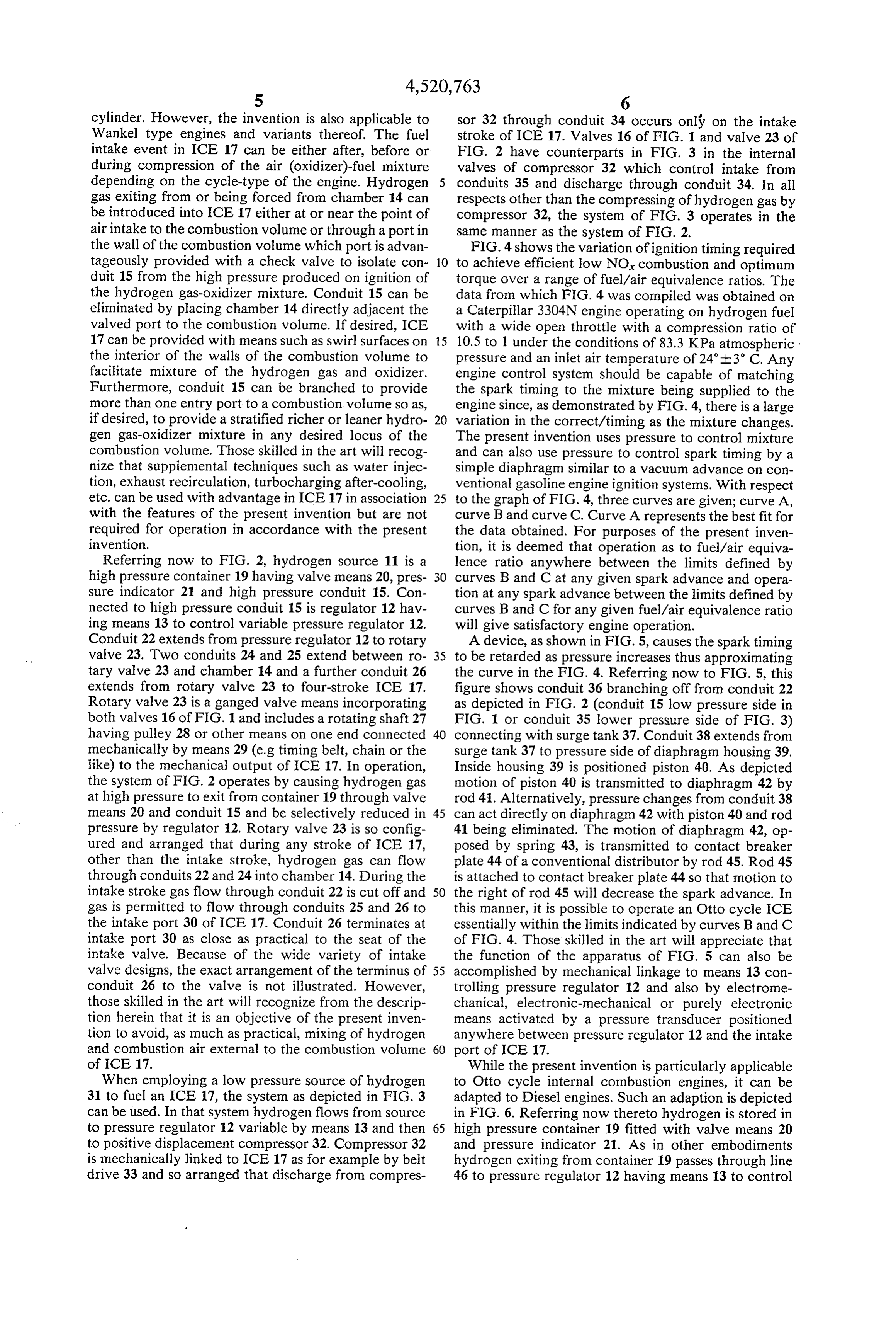
cylinder. However, the invention is also applicable to sor 32 through conduit 34 occurs only on the intake Wankel type engines and variants thereof. The fuel stroke of ICE 17. Valves 16 of FIG. 1 and valve 23 of intake event in ICE 17 can be either after, before or FIG. 2 have counterparts in FIG. 3 in the internal during compression of the air (oxidizer)-fuel mixture valves of compressor 32 which control intake from depending on the cycle-type of the engine. Hydrogen conduits 35 and discharge through conduit 34. In all gas exiting from or being forced from chamber 14 can respects other than the compressing of hydrogen gas by be introduced into ICE 17 either at or near the point of compressor 32, the system of FIG. 3 operates in the air intake to the combustion volume or through a port in same manner as the system of FIG. 2. the wall of the combustion volume which port is advan FIG. 4 shows the variation of ignition timing required tageously provided with a check valve to isolate con 10 to achieve efficient low NOx combustion and optimum duit 15 from the high pressure produced on ignition of torque over a range of fuel/air equivalence ratios. The the hydrogen gas-oxidizer mixture. Conduit 15 can be data from which FIG. 4 was compiled was obtained on eliminated by placing chamber 14 directly adjacent the a Caterpillar 3304N engine operating on hydrogen fuel valved port to the combustion volume. If desired, ICE with a wide open throttle with a compression ratio of 17 can be provided with means such as swirl surfaces on 15 10.5 to 1 under the conditions of 83.3 KPa atmospheric the interior of the walls of the combustion volume to pressure and an inlet air temperature of 24+3° C. Any facilitate mixture of the hydrogen gas and oxidizer. engine control system should be capable of matching Furthermore, conduit 15 can be branched to provide the spark timing to the mixture being supplied to the more than one entry port to a combustion volume so as, engine since, as demonstrated by FIG. 4, there is a large if desired, to provide a stratified richer or leaner hydro 20 variation in the correct/timing as the mixture changes. gen gas-oxidizer mixture in any desired locus of the The present invention uses pressure to control mixture combustion volume. Those skilled in the art will recog and can also use pressure to control spark timing by a nize that supplemental techniques such as water injec simple diaphragm similar to a vacuum advance on con tion, exhaust recirculation, turbocharging after-cooling, ventional gasoline engine ignition systems. With respect etc. can be used with advantage in ICE 17 in association 25 to the graph of FIG. 4, three curves are given; curve A, with the features of the present invention but are not curve B and curve C. Curve A represents the best fit for required for operation in accordance with the present the data obtained. For purposes of the present inven invention. tion, it is deemed that operation as to fuel/air equiva Referring now to FIG. 2, hydrogen source 11 is a lence ratio anywhere between the limits defined by high pressure container 19 having valve means 20, pres 30 curves B and C at any given spark advance and opera sure indicator 21 and high pressure conduit 15. Con tion at any spark advance between the limits defined by nected to high pressure conduit 15 is regulator 12 hav curves B and C for any given fuel/air equivalence ratio ing means 13 to control variable pressure regulator 12. will give satisfactory engine operation. Conduit 22 extends from pressure regulator 12 to rotary A device, as shown in FIG. 5, causes the spark timing valve 23. Two conduits 24 and 25 extend between ro 35 to be retarded as pressure increases thus approximating tary valve 23 and chamber 14 and a further conduit 26 the curve in the FIG. 4. Referring now to FIG. 5, this extends from rotary valve 23 to four-stroke ICE 17. figure shows conduit 36 branching off from conduit 22 Rotary valve 23 is a ganged valve means incorporating as depicted in FIG. 2 (conduit 15 low pressure side in both valves 16 of FIG. 1 and includes a rotating shaft 27 FIG. 1 or conduit 35 lower pressure side of FIG. 3) having pulley 28 or other means on one end connected 40 connecting with surge tank 37. Conduit 38 extends from mechanically by means 29 (e.g. timing belt, chain or the surge tank 37 to pressure side of diaphragm housing 39. like) to the mechanical output of ICE 17. In operation, Inside housing 39 is positioned piston 40. As depicted the system of FIG. 2 operates by causing hydrogen gas motion of piston 40 is transmitted to diaphragm 42 by at high pressure to exit from container 19 through valve rod 41. Alternatively, pressure changes from conduit 38 means 20 and conduit 15 and be selectively reduced in 45 can act directly on diaphragm 42 with piston 40 and rod pressure by regulator 12. Rotary valve 23 is so config 41 being eliminated. The motion of diaphragm 42, op ured and arranged that during any stroke of ICE 17, posed by spring 43, is transmitted to contact breaker other than the intake stroke, hydrogen gas can flow plate 44 of a conventional distributor by rod 45. Rod 45 through conduits 22 and 24 into chamber 14. During the is attached to contact breaker plate 44 so that motion to intake stroke gas flow through conduit 22 is cut off and 50 the right of rod 45 will decrease the spark advance. In gas is permitted to flow through conduits 25 and 26 to this manner, it is possible to operate an Otto cycle ICE the intake port 30 of ICE 17. Conduit 26 terminates at essentially within the limits indicated by curves B and C intake port 30 as close as practical to the seat of the of FIG. 4. Those skilled in the art will appreciate that intake valve. Because of the wide variety of intake the function of the apparatus of FIG. 5 can also be valve designs, the exact arrangement of the terminus of 55 accomplished by mechanical linkage to means 13 con conduit 26 to the valve is not illustrated. However, trolling pressure regulator 12 and also by electrome those skilled in the art will recognize from the descrip chanical, electronic-mechanical or purely electronic tion herein that it is an objective of the present inven means activated by a pressure transducer positioned tion to avoid, as much as practical, mixing of hydrogen anywhere between pressure regulator 12 and the intake and combustion air external to the combustion volume 60 port of ICE 17.
of ICE 17. While the present invention is particularly applicable When employing a low pressure source of hydrogen to Otto cycle internal combustion engines, it can be 31 to fuel an ICE 17, the system as depicted in FIG. 3 adapted to Diesel engines. Such an adaption is depicted can be used. In that system hydrogen flows from source in FIG. 6. Referring now thereto hydrogen is stored in to pressure regulator 12 variable by means 13 and then 65 high pressure container 19 fitted with valve means 20 to positive displacement compressor 32. Compressor 32 and pressure indicator 21. As in other embodiments is mechanically linked to ICE 17 as for example by belt hydrogen exiting from container 19 passes through line drive 33 and so arranged that discharge from compres 46 to pressure regulator 12 having means 13 to control
Page 8
pressure regulator 12. Hydrogen gas at some lower 5. A fuel injection system as in claim 1 wherein said pressure exits from pressure regulator 12 through con chamber includes means for varying the volume duit into chamber 14 when valve 16 is open. During a thereof.
fuel intake event of diesel ICE 49 valve 16 is closed and 6. A fuel injection system as in claim 5 wherein said valve 48 between chamber 14 and diesel ICE 49 is open. means for varying the volume of said chamber com Valve 48 can be a modified, enlarged fuel injection prises a piston.
valve on diesel ICE 49. Assuming that diesel ICE 49 7. A fuel injection system as in claim 1 wherein the operates at a 25 to 1 compression ratio, peak pressures in internal
combustion engine is an Otto cycle engine.
fuel injection system as in claim 7 which includes a naturally aspirated engine prior to fuel injection will be of the order of 4000 KPa. In order for hydrogen to O afrom pressure sensing means in said system downstream be injected into the combustion volume of diesel ICE 49 meanssaid means for controlling pressure coupled to a the pressure in chamber 14 either exceeds 4000 KPa by cycle enginecontrolling for to thereby the spark timing of said Otto advance said timing when pres a substantial margin or a pressure increasing device sure is low and retard said such as pump 51 must be included in alternate hydrogen 5 9. A fuel injection systemtiming when pressure is high. feed line 50. As those skilled in the art will recognize, and arranged that its fuel-air equivalence7 so as in claim constructed hydrogen injected into diesel ICE 49 can be injected bustion volume of said Otto cycle engine is inlessa con ratio than directly into a cylinder or into precombustion chamber about 0.7.
or a swirl chamber. For reliable operation, it is neces 10. A fuel injection system as in claim 9 wherein the sary to modify diesel ICE 49 by inclusion therein of an 20 fuel-air volume ratio is in the range of about 0.07 to ignition device 52 because, as stated hereinbefore hy about 0.30.
drogen-air mixtures do not reliably ignite solely under 11. A fuel injection system as in claim 7 wherein said compression condition. Otto cycle engine is of a piston-cylinder design. In this specification, it has been disclosed that pres 12. A fuel injection system as in claim 11 wherein sure control of hydrogen exiting from a hydrogen 25 conduit means between said chamber and the cylinder source is by means of a pressure regulator. Those skilled of said Otto cycle engine terminates in an air feed line as in the art will appreciate that such pressure regulation close to an air intake valve as is practical. can also be accomplished by employing any sort of 13. A fuel injection system as in claim 12 wherein said adjustable valve such as a butterfly valve, a plug valve, conduit means between said chamber and said cylinder a variable orifice valve and the like. 30 comprises essentially a valved port on said chamber Although the present invention has been described in opening onto the air feed line of said Otto cycle engine. conjunction with preferred embodiments, it is to be 14. A fuel injection system as in claim 1 coupleable to understood that modifications and variations may be a source of low pressure hydrogen wherein said cham resorted to without departing from the spirit and scope ber comprises the displacement volume of a positive of the invention, as those skilled in the art will readily 35 displacement-type compressor. understand. Such modifications and variations are con 15. A fuel injection system as in claim 1 wherein said sidered to be within the purview and scope of the inven means, timed to said internal combustion engine com tion and appended claims. prises ganged rotary valves mechanically linked to a We claim: mechanical output of said internal combustion engine. 1. A fuel injection system for an internal combustion 40 16. A fuel injection system as in claim 1 wherein said engine coupleable to a source of gaseous hydrogen means, timed to said internal combustion engine com comprising a means for controlling pressure, a means to prises valves of a positive displacement-type compres selectively vary said pressure control means, a chamber sor driven by mechanical linkage from the mechanical into which hydrogen gas of regulated pressure can flow 45 output of said internal combustion engine. from said pressure control means, conduit means be means tofuelselectively 17. A injection system as in claim 2 wherein said vary said regulator comprises a tween said pressure control means and said chamber linkage to a pedal speed control. and a combustion volume of said internal combustion engine and means, timed to said internal combustion means 18. A fuel injection system as in claim 2 wherein said engine, whereby during a fuel intake event of said com 50 back meansto selectively vary said regulator comprise feed bustion volume of said engine flow of hydrogen from internal combustion responsive to load or speed sensing of said engine.
said chamber to a combustion volume of said engine is 19. A fuel injection system as in claim 17 wherein said permitted and from said pressure control means to said linkage to a pedal speed control is a mechanical linkage. chamber is prohibited and whereby the absence of a fuel 20. A fuel injection system as in claim 1 wherein said intake event of said combustion volume of said engine, 55 internal combustion engine is a modified diesel cycle flow of hydrogen is permitted from said pressure con engine fitted with an ignition device. trol means to said chamber and prohibited from said 21. A fuel injection system as in claim 20 coupleable chamber to said combustion volume of said internal to a source of hydrogen at a pressure significantly combustion engine. greater than the internal pressure of air in said combus 2. A fuel injection system as in claim 1 wherein said 60 tion volume of said diesel cycle engine prior to fuel means for controlling pressure is a regulator. injection.
3. A fuel injection system as in claim 1 wherein said 22. A fuel injection system as in claim 20 which in means for controlling pressure is a variable valve. cludes compressor means to raise the pressure of hydro 4. A fuel injection system as in claim 1 coupleable to gen to injection pressure.
a hydride hydrogen storage means. 65 k ck ck
Provenance
- Collection
- Cited prior art
- Original PDF
- patentimages.storage.googleapis.com →
- Filed
- 1984-06-06
- Pages
- 8
- Method
- pdftotext (the PDF's own text layer) + pdftoppm 300dpi page scans
- Source
- Google Patents bibliographic record
- Granted
- 1985-06-04
- Inventors
- Franklin E. Lynch; Nathaniel R. Baker; Ergenics Inc
- Transcribed from
- patentimages.storage.googleapis.com →