patent · US4715326
Multicylinder catalytic engine
29 December 1987
Page 1 — bibliographic record
United States Patent (19) (11) Patent Number: 4,715,326 Thring 45 Date of Patent: Dec. 29, 1987 54 MULTICYLINDER CATALYTIC ENGINE 4,114,567 9/1978 Burton ............................ 23/143 R 4,344,405 8/1982 Zaharis.................................. 123/68 75 Inventor: Robert H. Thring, San Antonio, Tex. 4,369,746 1/1983 Thring ...... ... 123/272 (73 Assignee: Southwest Research Institute, San 4,389,983 6/1983 Enga et al. ... 123/143 B 4,422,412 12/1983 Norton .................................... 123/3
Antonio, Tex. 4,512,673 4/1985 Breguet ............................... 123/272 21 Appl. No.: 905,003 Primary Examiner-E. Rollins Cross 22 Filed: Sep. 8, 1986 Attorney, Agent, or Firm-Fulbright & Jaworski 51) Int. Cl* .............................................. FO2B 43/08 (57) ABSTRACT 52 U.S. C. ........................................ 123/3; 123/543; An unthrottled multicylinder catalytic engine having
(58) Field of Search ............... 123/1 A, 3, 143 B, 144, first and second cylinders with first and second pistons, 123/272, 546, 543 respectively, reciprocating therein. A mixture of air and fuel is inserted into the first cylinder, compressed in the 56) References Cited first cylinder, and combustion is initiated, if necessary,
642,176 1/1900 Thomson ........................ 123/143 B between the first and second cylinders receives the 1,105,047 7/1914. Thomson ........................ 123/143 B compressed mixture and a catalyst positioned in the 1,372,216 3/1921 Casaday .......................... 123/143 B passageway oxidizes or ignites the mixture to provide 1,819,825 8/1931 Poyer .............................. 123/143 B the power stroke for operating the second piston. 1,889,270 1 1/1932 Thomas et al. ..................... 23/546 Thereafter, the oxidized or burnt mixture is exhausted 2,091,410 8/1937 Mallory ........ ... 23/143 R from the second cylinder. The compressed gas may be 2,196,228 4/1940 Prescott .... ... 123/143 B heated in the passageway by the exhaust heat. 3,177,856 4/1965 Perkins .................................. 123/68 3,923,011 2/1975 Pfefferle .......................... 123/143 B 4,011,839 3/1977 Pfefferle .......................... 123/143 B 8 Clains, 1 Drawing Figure
Page 2
Drawing sheet — no readable text.
Page 3
products from the second cylinder after the conclusion
MULTICLNDER CATALYTC ENGINE of the power stroke.
Still a further object of the present invention is the
BACKGROUND OF THE INVENTION provision of a heat exchanger positioned adjacent the passageway and connected to the exhaust port for heat
It is desirable that an internal combustion engine be 5 ing efficient, perform well over a varied load range, have the compressed mixture in the passageway from the good fuel economy and low atmospheric pollution. One waste exhaust heat.
of the types of engines used to achieve this end is the whereina the
Yet further object of the present invention is air/fuel mixing means includes a carbure stratified charge engine, where a spark ignites a mixture O tor, or fuel injector.
in a zone where the air/fuel ratio is rich and the charge Still a further object of the present invention is stratification allows unthrottled operation even at light wherein the second piston leads the first piston by a loads. This tends to give good economy and low emis crank angle of between 45" and 90'.
sions of nitrogen oxide (NOX) and carbon monoxide Still a further object of the present invention is the (CO), but the emissions of unburned hydrocarbons 15 provision of a combustion initiating means, such as a (HC) tend to be high. The reason for the high hydrocar spark plug, in the first cylinder for use during startup. bons is that the flame is quenched by the lean air/fuel Yet still a further object of the present invention is the ratio before all of the fuel is burnt. In an attempt to method of operating a catalytic internal combustion overcome these problems, the catalytic engine was engine having first and second cylinders with first and proposed. With the catalytic engine, fuel is injected second pistons, respectively, reciprocating therein. The directly into the engine combustion chamber and the method includes premixing an air/fuel mixture and air/fuel mixture is oxidized and ignited with the aid of a inserting the mixture in the first cylinder, compressing catalyst. The catalytic engine has the advantage of op the mixture in the first cylinder, transferring the com erating at low oxidation or flame temperatures, for pressed mixture from the first cylinder through a cata example less than 3500' F. for reducing NOX and CO 25 lyst for igniting or oxidizing the compressed mixture emissions, the catalyst in the engine cleans up the HC thereby providing an expanding gas and transferring the emissions without the need for a catalyst in the exhaust expanding gas to the second cylinder providing a power system, the engine operates over a wide range of con stroke for the second piston, and then exhausting the pression ratios and as the fuel oxidation is by catalytic burnt gases from the second cylinder. The method may action, rather than spark or compression ignition, the further include heating the compressed mixture in the engine will operate on fuels which have poor octane or first cylinder and/or heating the compressed mixture as cetane values. However, the disadvantage of a conven it leaves the first cylinder by passing it in heat exchange tional catalytic engine is that the fuel cannot be carbu with the waste exhaust gas from the second cylinder. reted and therefore (a) the engine must have an expen Other and further objects, features and advantages sive fuel injection system and (b) gaseous fuels cannot will be apparent from the following description of a presently preferred embodiment of the invention, given be used.
The present invention overcomes these problems as for the purpose of disclosure and taken in conjunction well as providing an engine that uses a catalyst and with the accompanying drawing.
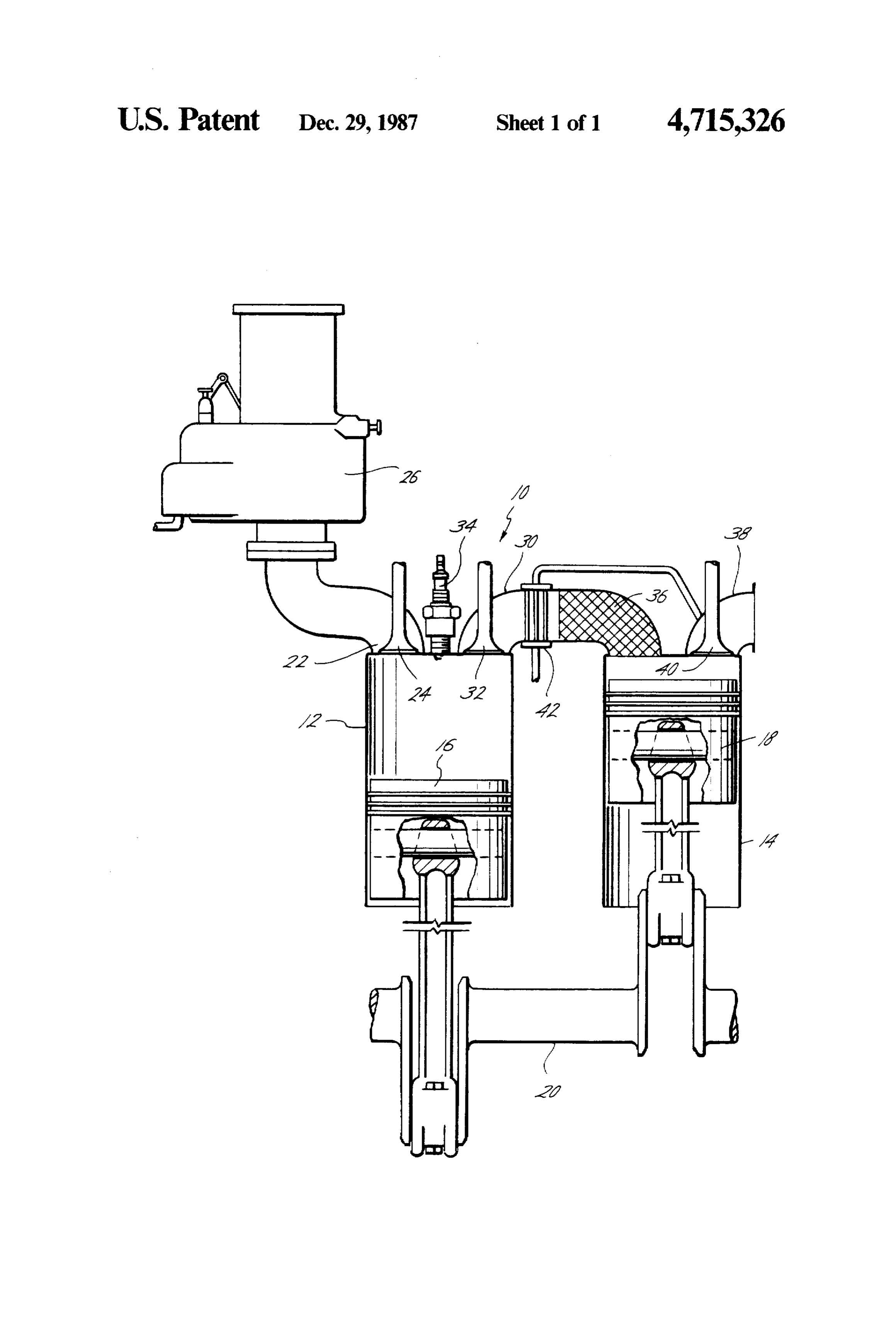
allows operations over the load range without throt BRIEF DESCRIPTION OF THE DRAWING tling and provides an engine which will, because the The FIG. is a schematic, partly in cross section, illus intake fuel/air mixture is premixed, use any fuel which trating the improved unthrottled catalytic engine of the can be carbureted including gaseous or liquid fuels. present invention.
SUMMARY DESCRIPTION OF THE PREFERRED
The present invention is directed to an unthrottled EMBOOMENT multicylinder catalytic engine having a first cylinder and a first piston reciprocating therein and a second 10 generally indicatesthethedrawing, Referring now to the reference numeral cylinder and a second piston reciprocating therein. The invention and generally includes a engine catalytic first of the present cylinder 12 and first cylinder includes an intake port and an intake valve a second cylinder 14. A first piston 16 is reciprocally in the intake port. Air/fuel mixing means are provided connected to the intake port for providing a premixed ismounted in the first cylinder 12 and a second piston 18 reciprocally mounted in the second cylinder 14. Any air/fuel mixture to the first cylinder. The intake valve suitable means may be provided for reciprocating the opens as the first piston draws the air/fuel mixture into pistons 16 and 18 such as a conventional crankshaft 20. the first cylinder and the intake valve is closed as the 55 The first cylinder 12 includes an intake port 22 con first piston moves upwardly to compress the mixture. A nected to the head of the cylinder 12 and an intake valve transfer passageway is provided in communication be 24 positioned in the intake port 22 for opening and tween the first and second cylinders. A transfer valve is closing communication of the port 22 with the cylinder in the passageway adjacent the first cylinder and opens 12. An air/fuel mixing means, such as a carburetor 26, is when the mixture in the first cylinder is compressd for connected to the intake port 22 for premixing air and transferring the compressed mixture from the first cyl fuel together prior to their admission into the cylinder inder toward the second cylinder. A catalyst is posi 12. The intake valve 24 is opened as the first piston 16 tioned in the passageway downstream of the transfer moves downwardly for drawing in the air/fuel mixture valve for oxidizing or igniting the compressed mixture into the cylinder 12 from the intake port 22. The intake when the transfer valve is closed thereby powering the 55 valve 24 then closes and the piston 16 is moved up second piston. An exhaust port is connected to the sec wardly to compress the mixture in the cylinder 12. ond cylinder and an exhaust valve is positioned in the A transfer passageway 30 is provided between the exhaust port for opening and exhausting the combustion first cylinder 12 and the second cylinder 14, preferably
Page 4
between their heads. A transfer valve 32 is provided in premixing an air/fuel mixture and inserting the mixture the passageway 30, preferably in the head of the cylin into the first cylinder, the method also includes com der 12, for allowing or blocking communication of the pressing the mixture in the first cylinder, transferring transfer passageway 30 with the cylinder 12. The valve the compressed mixture from the first cylinder through 32 is closed while the air/fuel mixture is being drawn in a catalyst for igniting the compressed air/fuel mixture to the cylinder 12 by the piston 16 and as the piston 16 thereby providing an expanding gas, transferring the travels upwardly to compress the mixture. The valve 32 expanding gas to the second cylinder providing a power is opened, just before the piston 16 reaches top dead stroke for the second cylinder, and exhausting the ex center, to allow the now-compressed air/fuel mixture to panding gas from the second cylinder. The method be transferred into the passageway 30. A combustion O further includes initiating combustion of the com initiating means such as a spark plug 34 is provided in pressed mixture in the first cylinder and/or heating the the cylinder 12 for use during the startup of the engine compressed mixture as it leaves the first cylinder from 10 and is energized approximately the time that the the heat from the waste heat exhaust gases from the valve 32 is opened for initiating ignition of the mixture, second cylinder.
but once the catalyst is hot, as will be more fully de 5 The present invention, therefore, is well adapted to scribed hereinafter, energization of the spark plug 34 is carry out the objects and attain the ends and advantages no longer needed. mentioned as well as others inherent therein. While a A catalyst 36 is positioned in the passageway 30 presently preferred embodiment of the invention has downstream of the transfer valve 32. The catalyst 36 been given for the purpose of disclosure, numerous may be of any sutiable form and material such as in the changes in the details of construction and arrangement form of metallic mesh, wool, ceramic monolith, or of parts and steps of the method will be readily apparent beads, and may contain platinum, rhodium, or other to those skilled in the art and which are encompassed suitable catalytic material. After the compressed mix within the spirit of the invention and the scope of the ture leaves cylinder 12, the transfer valve 32 closes and the mixture flows through the catalyst 36 where it is appended
What is claimed is:
oxidized with the aid of the catalyst, ignited and heat 1. A multicylinder catalyst engine comprising, release is initiated causing an expansion of the air/fuel a first cylinder and a first piston reciprocating therein, mixture. The burning expanding combustion gases then a second cylinder and a second piston reciprocating flow into the second cylinder 14 to provide the working stroke for driving the piston 18 downwardly. An ex 30 saidtherein, first cylinder including an intake port, haust port 38 is provided in the cylinder 14, preferably an intake valve in the intake port admitting all of the in the head, with an exhaust valve 40 positioned in the air and fuel for the engine, exhaust port 38 for exhausting burnt gases from the air/fuel mixing means connected to the intake port, second cylinder 14. The valve 40 is closed during the power stroke but opens after the end of the power 35 saiddraws intake valve being opened as the first piston an air/fuel mixture into the first cylinder, stroke to allow the upwardly moving piston 18 to eject the exhaust through the port 38. and said intake valve being closed as the first piston For improving the thermal efficiency of the engine moves to compress the mixture, 10, a heat exchanger 42 may be provided in the transfer a transfer passageway in communication between the passageway 30 upstrean of the catalyst 36 for receiving first and second cylinders, a portion or all of the hot exhaust gases from the port a transfer valve in the passageway adjacent the first 12. The waste heat from the exhaust gases is applied to cylinder closing while the air/fuel mixture is the compressed mixture in the passageway 30 before the drawn into the first cylinder and opening when the heat release occurs by the action of the catalyst 36. mixture in the first cylinder is compressed for The pistons 16 and 18 are timed with any suitable transferring the compressed mixture from the first actuation mechanism, such as the crank shaft 20, so that cylinder toward the second cylinder, the piston 18 leads piston 16 by a crank angle of 45 to a catalyst positioned in the passageway downstrean 90', preferably 70'. The valves 24, 32 and 40 may be of the transfer valve for igniting the compressed timed by the crank shaft 20 and any suitable valve mixture when the transfer valve is closed thereby mechanism to coordinate their movements with the 50 powering the second piston, pistons 16 and 18 as described above. an exhaust port connected to the second cylinder, and The present engine has the advantages that the fuel an exhaust valve positioned in the exhaust port for can be carbureted and therefore does not require an exhausting gas from the second cylinder. expensive fuel injection system, gaseous fuels can be 2. The apparatus of claim 1 including a heat ex used, the engine allows operation over the load rnage 55 changer positioned adjacent the passageway and con without throttling, the engine has low emissions of nected to the exhaust port for heating the compressed NOX and CO and HC, and the engine has no octane or mixture in the passageway from the waste exhaust heat. cetane requirements. In addition, because the air/fuel 3. The apparatus of claim 1 wherein the air/fuel mix mixture is premixed, any fuel which can be carbureted ing means includes a carburetor.
can be used, including gaseous or liquid fuels, such as 4. The apparatus of claim 1 wherein the second piston natural gas, methane, propane, gasoline, or wide-cut leads the first piston by a crank angle of between 45 petroleum fuel. and 90'.
The method of the present invention is apparent from 5. The apparatus of claim 1 including, the foregoing description of the structure and operation combustion initiating means in the first cylinder. of the engine. The method of operating a catalytic inter 6. The method of operating a catalytic internal com nal combustion engine having a first cylinder with a bustion engine having a first cylinder with a first piston first piston reciprocating therein and a second cylinder reciprocating therein and a second cylinder with a sec with a second piston reciprocating therein includes ond piston reciprocating therein comprising,
Page 5
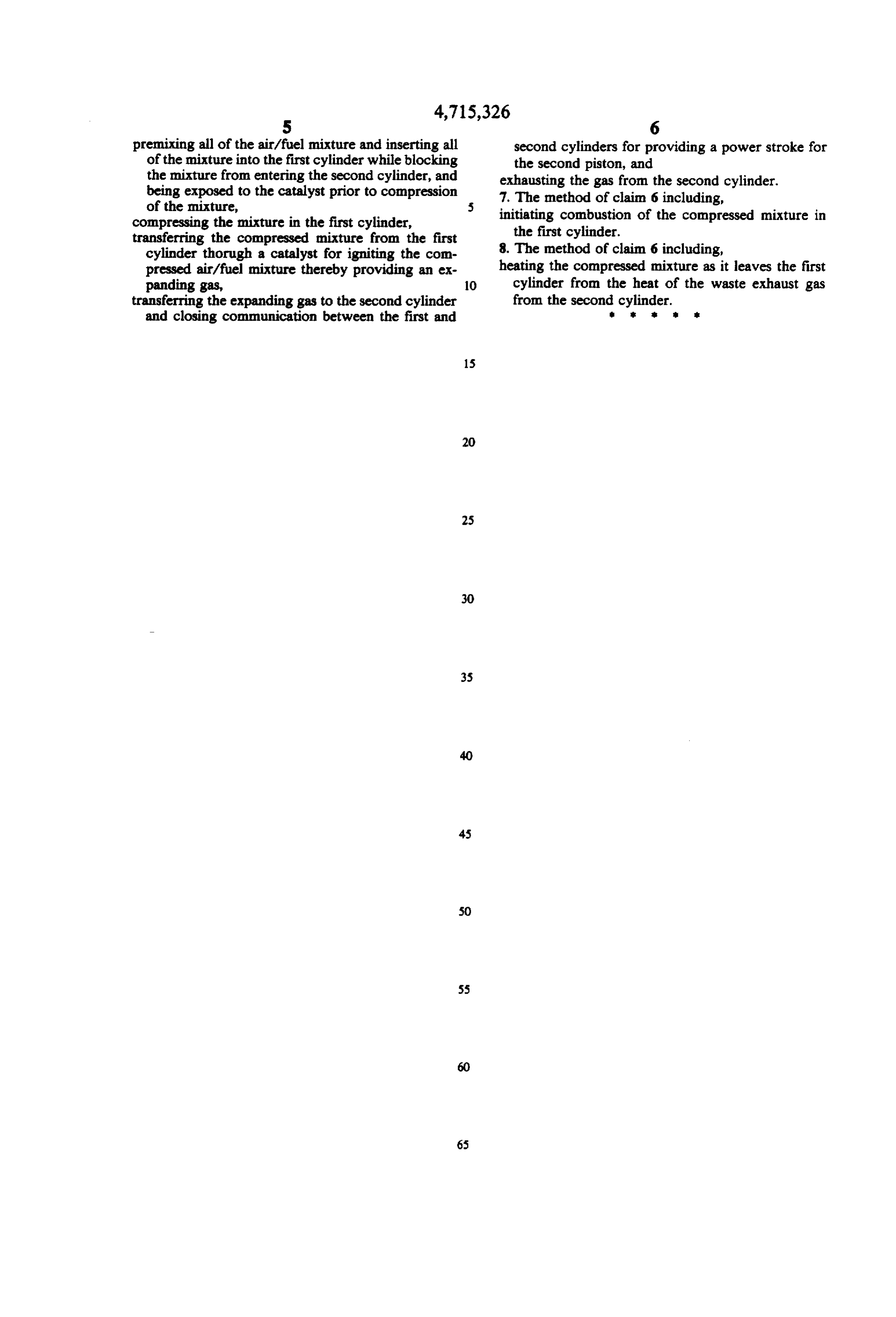
premixing all of the air/fuel mixture and inserting all second cylinders for providing a power stroke for of the mixture into the first cylinder while blocking the second piston, and the mixture from entering the second cylinder, and exhausting the gas from the second cylinder. being exposed to the catalyst prior to compression 7. The method of claim 6 including, of the mixture, initiating combustion of the compressed mixture in compressing the mixture in the first cylinder, the first cylinder.
transferring the compressed mixture from the first cylinder thorugh a catalyst for igniting the con 8. The method of claim 6 including, pressed air/fuel mixture thereby providing an ex heating the compressed mixture as it leaves the first panding gas, O cylinder from the heat of the waste exhaust gas transferring the expanding gas to the second cylinder from the second cylinder. and closing communication between the first and
Page 6
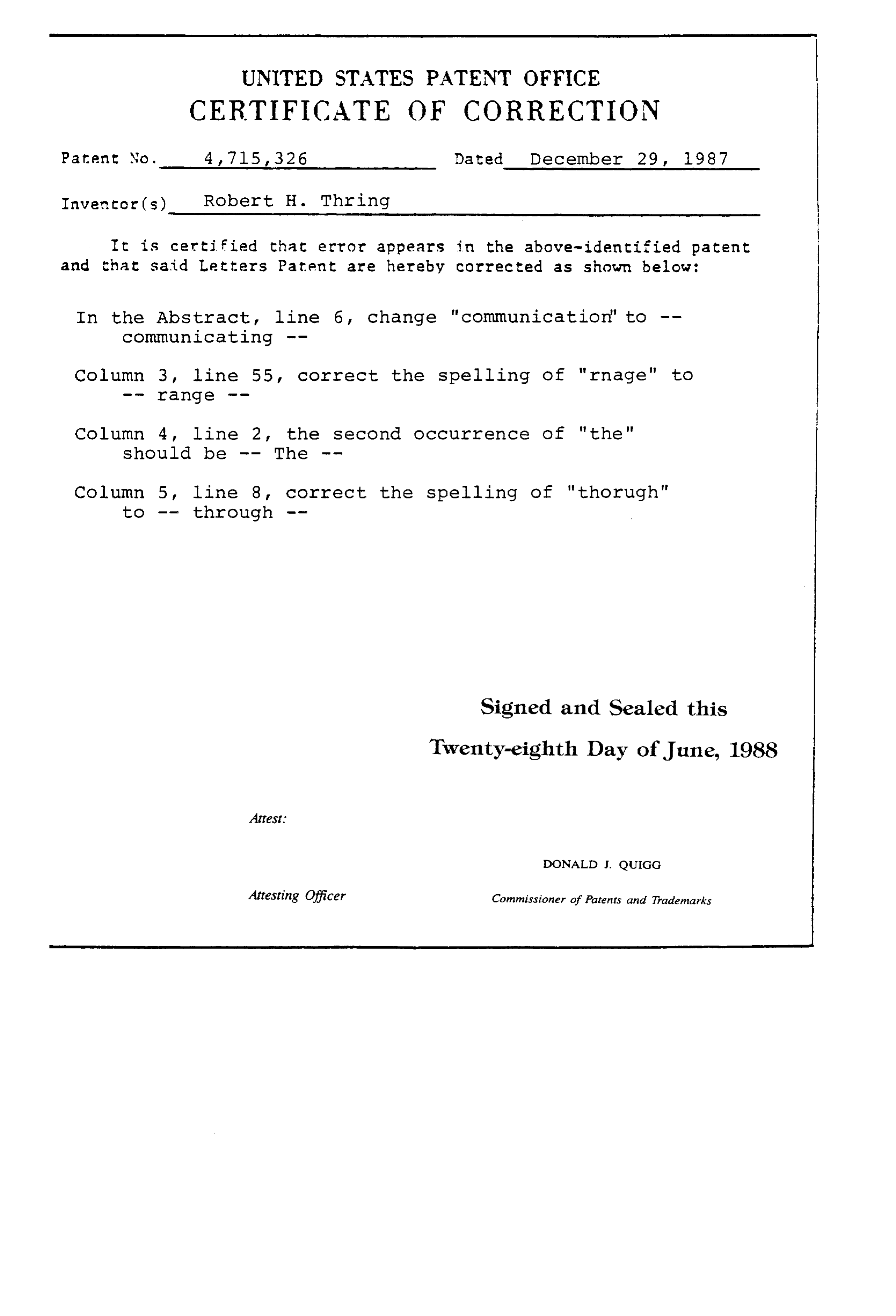
UNITED STATES PATENT OFFICE
CERTIFICATE OF CORRECTION
Pater No. 4, 715, 326 Dated December 29, 1987
Inventor(s) Robert H. Thring
It is certified that error appears in the above-identified patent and that said Letters Patent are hereby corrected as shown below:
In the Abstract, line 6, change "communication" to -- communicating --
Column 3, line 55, correct the spelling of "rnage" to
Column 4, line 2, the second occurrence of "the"
Should be -- The - -
Column 5, line 8, correct the spelling of "thorugh" to -- through --
Signed and Sealed this
Twenty-eighth Day of June, 1988
Attest.
DONALD J. QUIGG
Attesting Officer Commissioner of Patenirs and Trademarks
Provenance
- Collection
- Cited prior art
- Original PDF
- patentimages.storage.googleapis.com →
- Filed
- 1986-09-08
- Pages
- 6
- Method
- pdftotext (the PDF's own text layer) + pdftoppm 300dpi page scans
- Source
- Google Patents bibliographic record
- Granted
- 1987-12-29
- Inventors
- Robert H. Thring; Southwest Research Institute SwRI
- Transcribed from
- patentimages.storage.googleapis.com →