patent · US2724954
Apparatus for the operation of cold accumulators
29 November 1955
Page 1
Drawing sheet — no readable text.
Page 2
Nov. 29, 1955 A. MAETZ 2,724,954
APPARATUS FOR THE OPERATION OF COLD ACCUMULATORS
Filed April 15, 1952 2. Sheets-Sheet 2
a2. 6 24 AVS d co y year X W Sy
NVENTOR
August Moetz
ATTORNEYS
Page 3
United States Patent Office Patented Nov.2,724,954
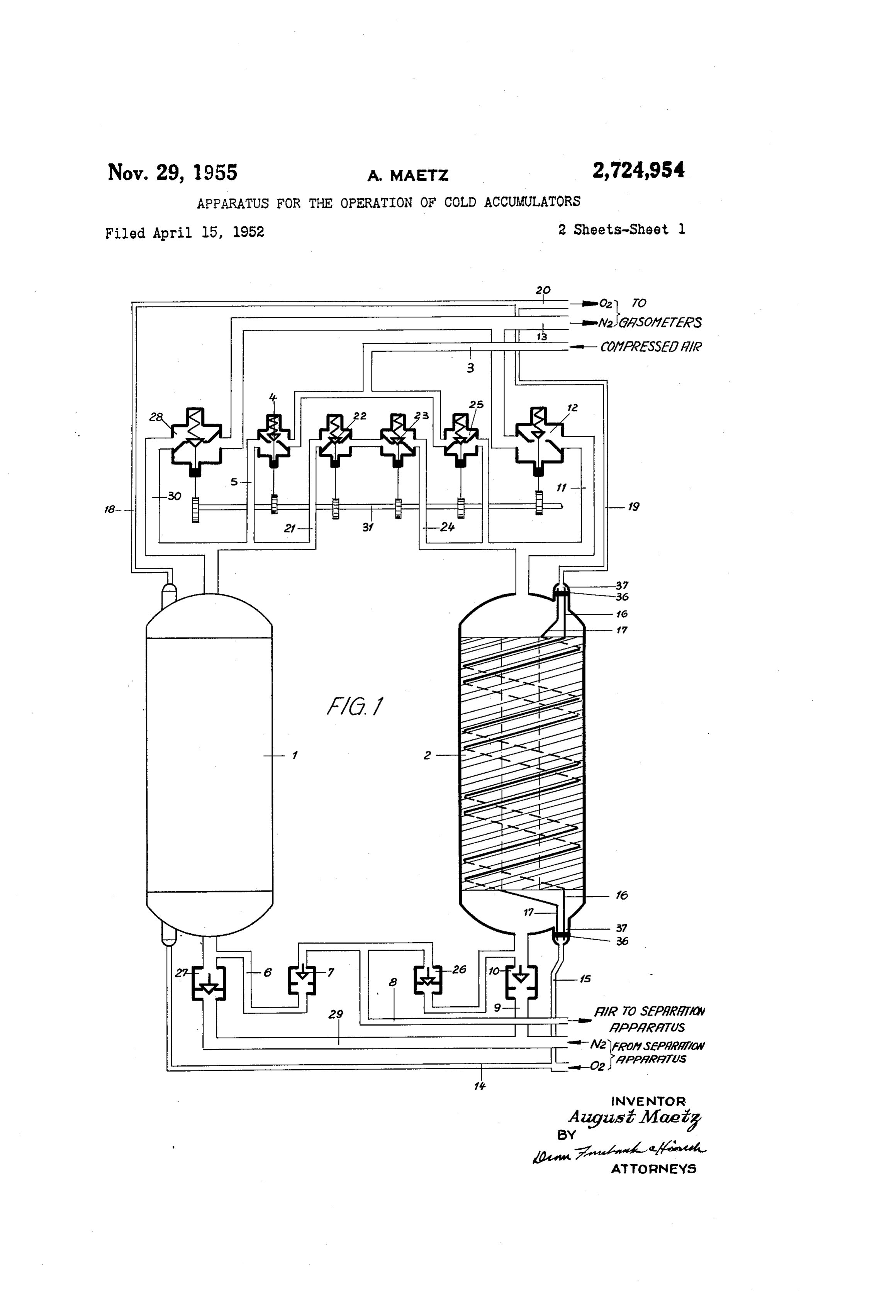
Figure 1 is a diagrammatic view partly in elevation and partly in section of a cold accumulator with the reversing 2,724,954 valves and inlet and outlet piping for the air to be sepa
APPARATUS FOR THE OPERATION OF
rated, and the separation products;
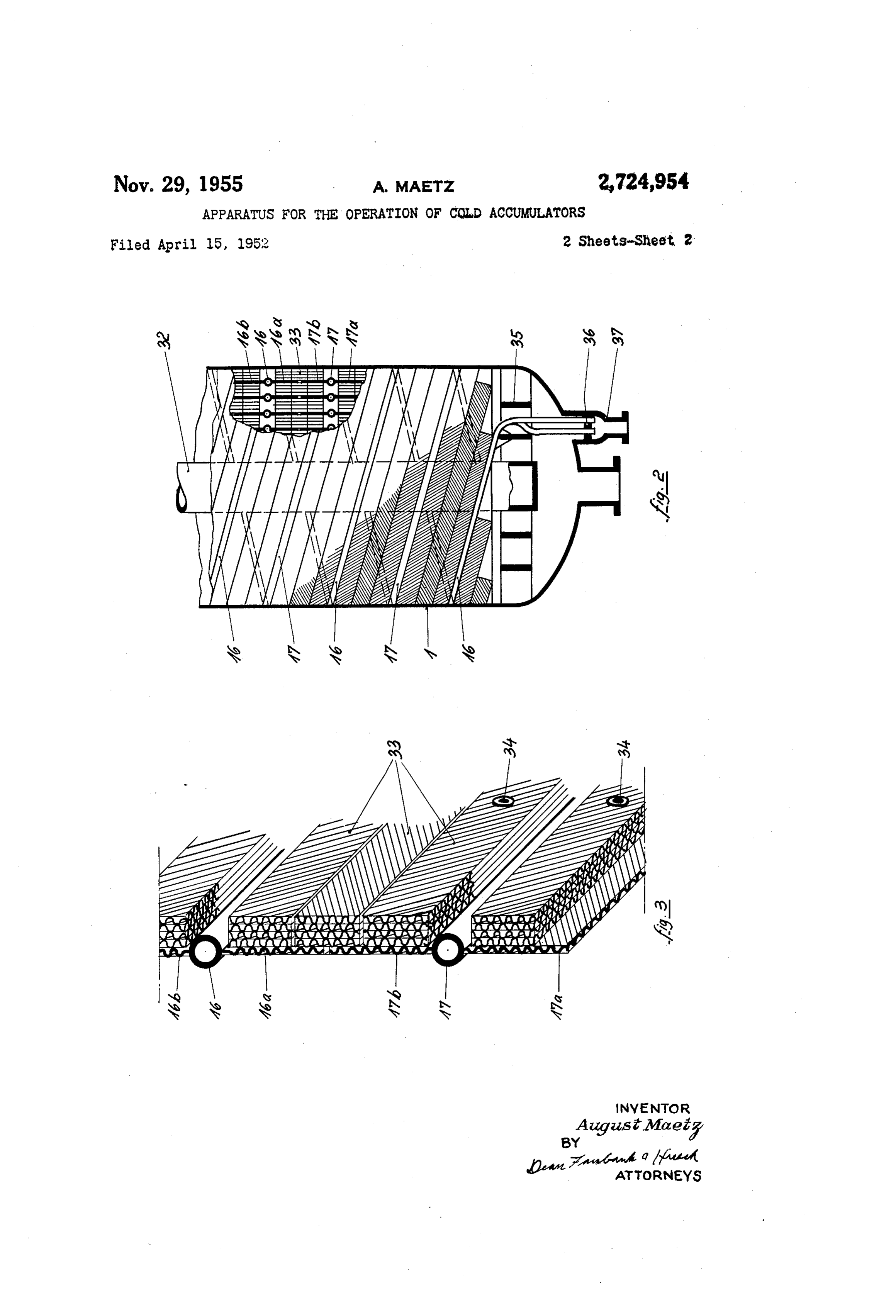
COLD ACCUMULATORS Figure 2 is a side elevation of the parts within the cold accumulator, a portion being in section; and
August Maetz, Frankfurt am Main, Fechenheim, Ger Figure 3 is a perspective view of a portion of one of many, assignor to Adolph Messer G. m. b. H., Frank the elements composing the cold accumulators. furt am Main, Germany, a corporation of Germany In Figure 1 the shells of two accumulators according Application April 15, 1952, Serial No. 282,357 0. to the invention are shown. The compressed air to be separated flows through the conduit 3, passes through 5 Claims. (C. 62-122) the valve 4, which is open and the conduit 5 and arrives at the cold accumulator 1, which it leaves at the tempera ture of about - 170° C. It then passes through the con
This invention relates to apparatus for the operation of 15 duit 6, the valve 7 and the conduit 8, in order to get into cold accumulators, as it is used in connection with the air separation apparatus, which may be of the usual, an apparatus for the separation of gas mixtures, and Well known type, as shown in the United States Patent more particularly for the liquefaction and rectification of No. 1,890,646. Simultaneously, the nitrogen flows from air; the use of tubular counter-current cold exchangers the separation apparatus through the conduit 9 and the for this purpose is known. Such exchangers consist of valve 10 into the cold accumulator. 2, where it gives up a substantial number of helically disposed pipes of copper its cold and which it leaves through the conduit 11, the or aluminum arranged in parallel, one portion of same valve 12 for passing by the conduit 13 into the gasholder. being passed by the flow of air in one direction, and The nitrogen is usually not required at a high degree of the other portion of same being passed by the cold prod purity. Therefore, it may absorb the moisture and the ucts of the separation process, oxygen and nitrogen, in 25 carbon dioxide deposited in the cold accumulator 2 dur opposite direction, whereby the cold of the separation ing the preceding operation period. Such separation products is given up to the air to be separated. . It is an products, however, which have to maintain their degree outstanding feature of these cold exchangers that the of purity, as for example the oxygen separated from the purity of the separation products, as they are delivered air, flow without interruption during the periodical re by the separation apparatus, is fully maintained. How 30 versing of the operation and without any manipulations ever, such cold exchangers have the disadvantage that of the valves continuously and constantly from the separa the air to be separated, before passing through the cold tion apparatus through the conduits 4 and 15 to the exchangers, has to be separated from the carbon dioxide cold accumulators 1 and 2, through which they are con and the moisture contained therein, which separation takes ducted by the spirally coiled conduits, of which the draw place in separate apparatus. Therefore another system 35 ing shows, for the sake of better clearness, the conduits of cold exchangers has been developed, which is known 16 and 17 only. On their passage, they give up their as the Linde Frankl recuperators. The cold exchangers cold to the cold accumulators 1 and 2. All the conduits of this type are described in Patents Nos. 1,945,634, are combined again after leaving the cold accumulators 2,107,335 and 2,513,306. in the common conduits 18 and 19, which are finally The type of such cold exchangers which is mostly in 40 combined into one conduit only 20, leading to the oxygen use, is an apparatus consisting of corrugated metal strips gasholder.
spirally disposed to form large disks, piled up one upon After a predetermined period corresponding to same of the other in substantial number. One of each pair of the usual cold accumulators, the cold accumulated in the these cold exchangers or cold accumulators is operated cold accumulator i during the preceding operating period by periodically reversing the direction of the flow and 45 has been absorbed so far by the air passing through same, by sending at certain intervals the air to be separated that any continuation of the process would increase the through one cold accumulator and the separation prod temperature of the air leaving the cold accumulator. Then ucts through the other one, and during the following pe the operation of both cold accumulators and 2 is ex riod, vice versa, the separation products through the first changed. For this purpose, the valves 4, 7, 0 and 12 one and the air to be separated through the other one. 50 are closed for obtaining first of all pressure compensa The separation products give up their cold on their pas tion between the cold accumulators i and 2 by way of sage to the cold accumulator, while during the following the conduit 21, the valves 22 and 23 and the conduit 24, period the air to be separated passing this cold accumula and for releasing the remaining overpressure through the tor in oposite direction will absorb the cold. The moisture valve 22 into the atmosphere, after having closed the and the carbon dioxide, which have been precipitated by 55 valve 23. After having closed the valve 22, the waives the air in the cold accumulator, are vaporised during the 25, 26, 27 and 28 are opened. Then the compressed following period by the separation products and removed air flows through the conduit 3, through the valve 25 from the cold accumulator. The advantage of this cold into the cold accumulator 2, and after being cooled down exchanging system is therefore, that there is no separate within the same, through the valve 26 and the conduit equipment for the removal of the carbon dioxide and the 60 8 to the separation apparatus. The nitrogen coming from moisture and that this equipment is consequently saved. the separation apparatus flows through the piping 29 and The disadvantage however is, that the separation products, the valve 27 into the cold accumulator 1, gives up its and more particularly the oxygen are contaminated by the cold there and leaves it through the conduit 30, the valve moisture and the carbon dioxide, so that a subsequent 28 and the conduit 3, for being sent into the nitrogen purification of the gas may be required. 65 gasholder. The regulation of the valves may be obtained,
The principal object of the present invention is to pro vide a cold exchanger, combining the advantages of the for example, by a cam shaft 31. At the end of this oper two above mentioned systems of cold exchangers without ating phase, both cold accumulators are exchanged again including their disadvantages. The above and other in their operation by the corresponding reversion of their objects and the novel features of the invention will be 70 valves. The oxygen stream is not touched at all by the apparent from the following specification and the accom manipulations.
panying drawing, in which: Figure 2 shows the lower portion of a cold accumula
Page 4
tor, according to the invention, partly in section. Within to the cold portion and one of the separation products the shell 1, the conduits for the oxygen are spirally rolled passing through the other accumulator from the cold up in various layers around the tubular cylinder 32, of portion to the warm portion thereof: means for inter which the conduits 16 and 17 are only shown by way of rupting the flow of said gases at the end of the predeter example. Each of such conduits, which may be made for mined period of time and compensating the pressures in example of aluminum, may be equipped with two cor said accumulators, means for exchanging the flows of rugated aluminum sheet strips with a view to improving said gases for other and special conduits within both the transfer or exchange of cold. The conduit 16 is accumulators for the other separation product to be re shown with the strips 16a and 16b and the conduit 17 10 covered cold pure, these separation products passing from the portion to the warm portion of the accumulators with the strips 17a and 17b. The pipes are so coiled up independently of the flows of the other gases outside of in each position that there is a small interspace between the special conduits, the conduit within the accumulator the edges of adjacent sheet strips. The distance between being helically disposed around a hollow cylinder, and two layers of coiled pipes are filled up with helically corrugated metal strips between successive turns of the rolled up corrugated strips, serving for the accumulation 5 coils and having a similar helical contour. of the cold. They form various thin channels passed 2. Apparatus for the cold exchange between a gas to during one operating period by the nitrogen, giving up its be separated by liquefaction and rectification and the cold to the sheet, and during the next operating period by the compressed air absorbing the cold accumulated by separation products, as claimed by claim 1, the special the sheets. The strips may be combined by rivets for 20 conduits being provided lengthwise at both sides with cor rugated metal strips.
facilitating the rolling up.
Figure 3 shows the design of one layer of coils in natur be3.separated
Apparatus for the cold exchange between a gas to by liquefaction and rectification and the al size in all details. The strip layers consist for example separation products, as defined in claim 1, and in which of four such superposed diagonally corrugated aluminum corrugated metal strips are disposed between and in con sheets, where the corrugations of two such superposed tact with the coils, and means for securing said strips at strips have a different direction. The strips 33 are held 25 the top and at the bottom of the accumulator. together by rivets 34. 4. Apparatus for cold exchange between a gas to be At both sides or ends of the cylinder 32 grates 35 are separated by liquefaction and rectification and the sepa fixed consisting of aluminum casting, to which the ends ration products, said apparatus including a casing having of the corrugated strips are welded. The conduits 16 30 an inlet and an outlet, an axially extended coiled con and 17 pass through the grates and are welded in clusters duit within said casing, and a layer of corrugated metal into the flanges 36, which are inserted into the branches in the form of a similarly coiled helix disposed between 37 of the conduits. successive turns of the coiled conduit. In the same way as the process and apparatus are de scribed above as applied to the cold exchange between 35 is 5.aluminum
Apparatus as set forth in claim 4 wherein the metal and is in contact with said coiled conduit air and the separation products, this invention can be along its longitudinal extent. similarly used for the reversals of cold and heat accu mulators between any given gas mixture and one of its References Cited in the file of this patent separation products. It is obvious that various changes may be made in the details of the above described process 40 UNITED STATES PATENTS and apparatus, without departing from the principles of 2,097,434 De Baufre ------------- Nov. 2, 1937 this invention. 2,107,335 Linde et al. -------------- Feb. 8, 1938 What I claim is: 2,214,672 Hausen -------------- Sept. 10, 1940 1. Apparatus for the cold exchange between a gas to 2,513,306 Garbo ---------------- July 4, 1950 be separated by liquefaction and rectification and the 45 2,586,207 Collins ---------------- Feb. 19, 1952 separation products comprising a pair of periodically re 2,648,205 Hufnagel -------------- Aug. 11, 1953 versible cold accumulators, each having a warm portion FOREIGN PATENTS and a cold portion, the compressed gas to be separated passing through one accumulator from the warm portion 276,381 Great Britain ---------- Aug. 18, 1927
Provenance
- Collection
- Cited prior art
- Original PDF
- patentimages.storage.googleapis.com →
- Filed
- 1952-04-15
- Pages
- 4
- Method
- pdftotext (the PDF's own text layer) + pdftoppm 300dpi page scans
- Source
- Google Patents bibliographic record
- Granted
- 1955-11-29
- Inventors
- Maetz August; ADOLPH MESSER GmbH
- Transcribed from
- patentimages.storage.googleapis.com →