patent · US3374158
High pressure electrolysis system and process for hydrogen-oxygen generation
19 March 1968
Page 1
March 19, 1968 A. M. LORD ETAL, 3,374,158
HIGH PRESSURE ELECTROLYSIS SYSTEM AND PROCESS FOR
HYDROGEN-OXYGEN GENERATION
Filed April 1, 1964
N S s N NN S. NS
N N S SN N R
N S.N NN W 5 S Ny Sy Vy S S V S V R - S
Page 2
United States Patent Office Patented Mar.3,374,158
3,374,158 lowing description taken in conjunction with the drawings GH PRESSURE ELECTROLYSS SYSTEM wherein like reference numerals refer to like and corre ANE PROCESS FOR HYDROGEN-OXYGEN sponding parts.
GENERATION In the drawings:
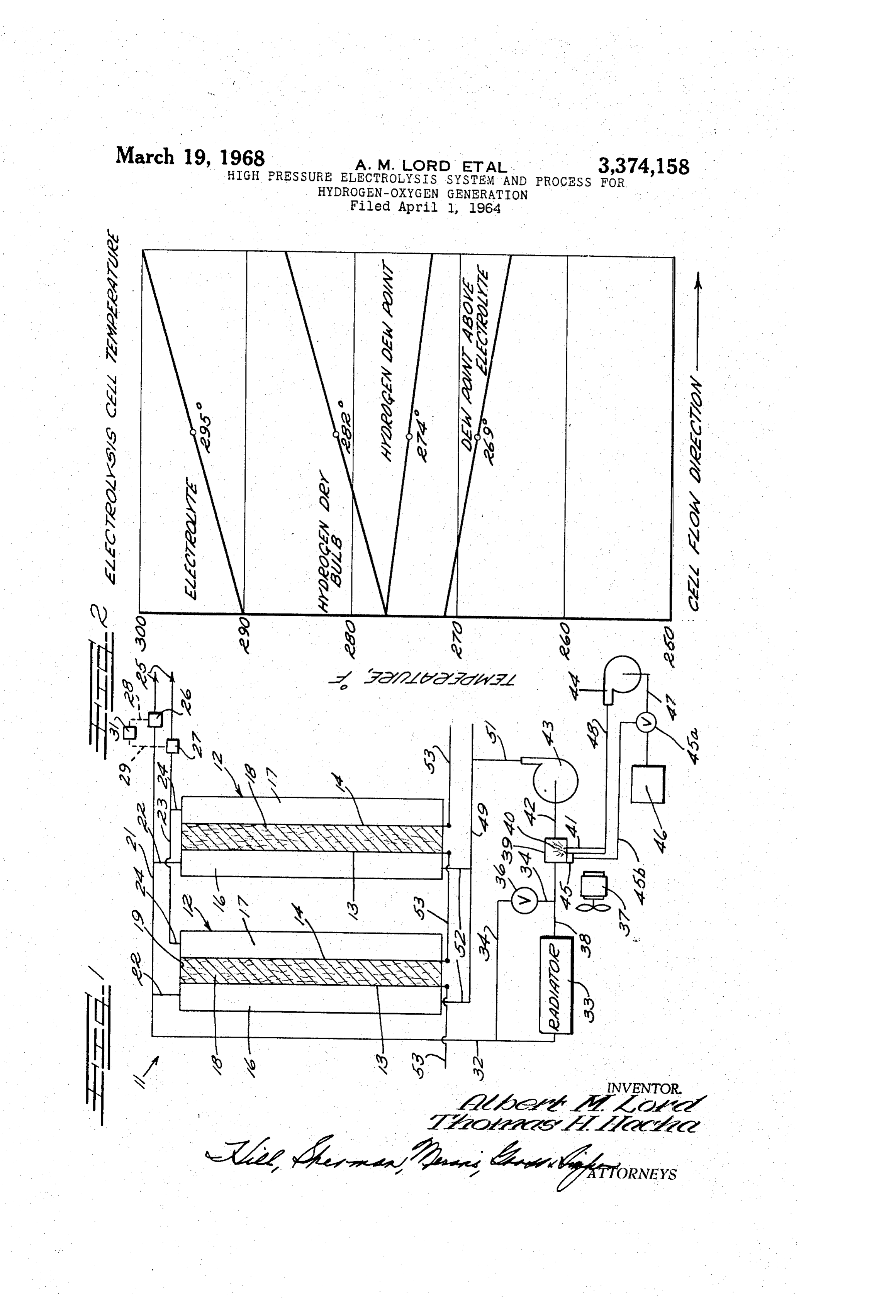
Albert M. Lord, Lakewood, and Thomas H. Hacha, 5 FIGURE 1 is a partial schematic view illustrating the Willoughby, Ohio, assignors to TRW Inc., a corporar tion of Ohio high-pressure electrolysis system of the present inven tion; and
Fied Apr. 1, 1964, Ser. No. 356,470 fIGURE 2 is a temperature graph illustrating the tem 9 Claims. (C. 204-129) perature profiles of the high-pressure water electrolysis 10 system of the present invention.
ABSTRACT OF THE DISCLOSURE As shown in the drawings:
Electrolysis system for hydrogen-oxygen generation cerned electrolysis
The with a system of the present invention is con compact high-pressure electrolysis system wherein a portion of one of the product gases is humid utilizing a plurality of electrolytic cells. The electrolytic ified and returned to a porous electrode in the electroly 5 cells have their electrodes electrically connected and pro sis cell to replenish the water used up during electrolysis. vide electrolyte cooling and replenishing by circulating a -sulaeamma portion of the gases evolved in each cell through a cool This invention generally relates to a high-pressure elec ing means, an electrolyte saturation means and then re trolysis system and more particularly relates to an in 20 turning the electrolyte containing gases to the electrode from which it was evolved to replenish the electrolyte by proved high-pressure electrolysis system. vapor diffusion and cool the electrolytic cells by sensible For exemplary purpose only, our invention will be heat transfer.
described in conjunction with a water electrolysis system Referring to FIGURE 1 there is illustrated a high wherein water is decomposed to produce hydrogen and pressure water electrolysis system 1 having a plurality oxygen gases. Water decomposition in the system de 25 of electrolytic cells 12. Each electrolytic cell 12 has a creases the water content of the electrolyte therein and pair of electrodes 13 and 14 dividing the cell into two produces heat that is absorbed by the electrolyte. In order gas chambers 16 and 17 and an electrolytic chamber 19. to avoid the detrimental aspects of replenishing the elec The electrolyte chamber is filled with an aqueous elec trolyte water content by the direct addition of water to the electrolyte in the electrolytic cells, known electrolysis 30 trolyte 18 such as an impervious asbestos matrix impreg nated with an aqueous electrolyte solution of potassium systems provide for constant recirculation of the elec hydroxide, trolyte wherein the electrolyte was replenished with water furic acid. Sodium hydroxide, phosphoric acid, or sul and cooled outside of the electrolytic cell. This arrange The electrodes 3 and 14 are sintered nickel porous ment required auxiliary equipment which made water plates electrolysis systems undesirably large and heavy for ef 35 screen varying from 0.004 to 0.020 inch thick, nickel of 0.003 inch wire with 80 wires per inch, nickel fective use for fuel cells utilized in aircrafts and for other Screen with a coating of platinum black, silver and tan purposes where weight and size are prime factors. The talum screens, or porous carbon plates. The electrical present invention provides an improved high-pressure Current may be delivered to the electrodes by metal electrolysis system having a plurality of electrolytic cells, Screens i.e. nickel or copper, which are positioned adja by maintaining the electrolyte in each electrolytic cell and 40 cent and in contact with the electrodes. recirculating a portion of the gases produced to cool the A hydrogen outlet manifold 21 is connected to each cells and replenish the electrolyte thereof by vapor diffu
SOI. gas chamber 16 by outlet conduits 22 and an oxygen Therefore, it is an object of the present invention to outlet manifold 23 is connected to each gas chamber 17 provide a high-pressure electrolysis system that replen by outlet conduits 24. The hydrogen manifold 21 has a ishes the electrolyte of the electrolytic cell by vapor dif fold relief valve 26 connected thereto and the oxygea mani fusion. 23 has a relief valve 27 connected thereto. The relief It is another object of the present invention to provide valves 26 and 27 are preferably interconnected respec a method of controlling the electrolyte concentration and 50 the tively by lines 28 and 29 to a control means 31 such that temperature by vapor diffusion. cathodic and anodic compartments 16 and 17 of the electrode it is still further another object of the present inven ence greater assemblies do not experience a pressure differ tion to provide an electrolysis system having a plurality Sure differentials than 1.0 p.s.i.a. Varied and substantial pres of electrolytic cells and electrolyte concentration and interfere with accurate in the compartments 16 and 7 will temperature control by vapor diffusion within each elec system controls and input vapor trolytic cell. 55 pressure levels in the system.
It is still another object of the present invention to manifolds The hydrogen and oxygen gases passing through the provide a high-pressure water electrolysis system having may 21 and 23 in the direction of the arrows 25 be delivered electrolyte concentration and temperature control by cir means Such as oxygen to a suitable fuel cell or other suitable culating, cooling, and humidifying a portion of the hy 60 A recirculating conduit or hydrogen fired engines. drogen gas produced. 32 is connected to the manifold Still another object of the present invention is to pro 21 and a radiator 33 to tap and deliver a portion of the vide a high-pressure water electrolysis system utilizing a hydrogen evolved in the hydrogen chamber 16 to the radiator. The radiator 33 cools the hydrogen by circulating plurality of electrolytic cells having electrolyte concen conduits and cooling fins (not shown). A fan means 37 tration and temperature control by cooling and humidify 65 blows ambient air over the radiator fins to thereby allow ing a portion of the hydrogen gas produced in each cell one radiator to cool the gases passing therethrough. A con and then returning the cooled and humidified hydrogen to duit 38 interconnects the radiator 33 with a spray vapor the cathode portion of each cell at such a temperature pressure increasing or humidifying chamber 39 to deliver and humidity that heat is removed and water vapor is cool hydrogen gas thereto. A heat exchanger by-pass con condensed on the electrolyte.
Other objects, features and advantages of the present 70 32, duit 34 interconnects the manifold 21, through the conduit invention will become apparent after considering the fol A normally to the conduit 38 to deliver hot hydrogen gas thereto. closed temperature sensitive valve 36 is
Page 3
mounted on the conduit 34 and is set to open at a pre showing the temperature profiles of one electrolytic cell determined temperature to control the sensible heat re with the left-hand portion of the graph illustrating the moved from the tapped hydrogen gas by the heat ex admission of saturated hydrogen to the cell and the right changer or radiator 33. hand portion indicating the exit of the hydrogen gas from The spray chamber 39 has a spray nozzle 41 mounted 5 the
cell. The vapor pressure of the electrolyte, as indicated the “Dew Point above electrolyte' line is less than the therein which is adapted to spray water into the spray vapor pressure of the saturated hydrogen, as indicated by chamber 39 to increase the humidity of the hydrogen gas the “Hydrogen Dew Point” line and therefore, water vapor passing therethrough. is transferred from the hydrogen to the electrolyte. A water pump 44 is connected to a water supply 46 by In an assembly utilizing 100 cells for electrolyzing 10 conduit 47 and delivers water under pressure to the nozzle O pounds per hour of water and wherein hydrogen and oxy 41 by conduit means 48. The nozzle 4f sprays water 49 gen gases are delivered at 4500 p.s.i.a. through the outlet into the chamber 39 to humidify the hydrogen gas passing valves 26 and 27, the power consumption is 45 kilowatts therethrough. The water spray rate is controiled by a gas at 300 volts. The cells operate at 300 F., with 6 N KOH temperature depression sensor 45 suitably connected to impregnated asbestos electrolytes. The entire assembly the spray chamber 39 and a water control valve 45a by consisting of 100 cells and all the temperature and water line 45b so that saturated hydrogen is delivered to spray feed controls may be contained in a pressurized cylinder chamber outlet conduit 42. The spray chamber outlet con 2i inches in diameter and 60 inches long with the cylin duit 42 connects the spray chamber 39 with a blower 43 der having external fins for cooling. The saturated or that delivers the saturated hydrogen gas to a hydrogen inlet manifold 49 by a conduit 5i connected to the hydro 20 humidified hydrogen is delivered to the cell through con duits 52 at 277 F. The system was tested with sintered gen blower outlet. A plurality of inlet conduits 52 inter nickel electrodes with the polarization data for gases being connect the hydrogen chambers 16 with the manifold 49. delivered to the valves 26 and 27 at 4500 p.s.i.a., calcu The electrolytic cells 12, as illustrated in FIGURE 1, lated as follows:
have their electrodes connected in electrical series. That is, the anodes 14 are connected to the cathodes 3 of ad 25 Current density jacent cells by suitable line means 53 with the end cells Volts: (amps./ft.9) having their free anode or cathode, as the case may be, 2.13 ----------------------------------- 50 connected to an electrical supply means (not shown) 2.75 ----------------------------------- 100 such as for example the very fuel cell to which the oxygen 2.96 ----------------- - - - - - - - - - - - - - - - - - - 150 and hydrogen is supplied by the electrolysis system since 30 only a very small amount of electrical input energy is In each cell, the hydrogen removes heat therefrom by needed. However, the cells 12 may be connected in elec Sensible cooling. The dry bulb hydrogen temperature is trical parallel if desired. That is, the anodes of each cell higher than the electrolyte saturation temperature, as is are connected to each other and the cathodes of each shown in FIGURE 1. The slopes of the sensible and latent cell connected to each other with one end cell having its 35 temperatures are adjusted to satisfy the cooling heat flux and water addition requirements of a 3-volt cell. The aver anode and cathode connected to the electrical current
Supply means. age electrolyte saturation temperature depression in this In operation, the electrolytic cells have their electrolyte, case corresponds to an average concentration slightly high an inert asbestos matrix impregnated with suitable aque 40 gas er than 6 N. The concentration will be lower at the air outs electrolyte solution, positioned between the cathode inlet side than at the outlet with the difference be and anode thereof. Hydrogen ions are reduced at the tween the concentration being reduced by increasing the cathodes 3 to produce hydrogen gas in the hydrogen hydrogen recirculation flow rate. cavities or chambers 16, and hydroxyl ions are oxidized at Another high-pressure electrolysis assembly has 100 the anodes 14 to produce oxygen gas in the oxygen cavities electrolytic cells and a power consumption of 30 kilo or chambers 17. The production of hydrogen and oxygen watts at 200 volts for electrolyzing 10 pounds per hour gases is such that the gases pass through the valves 26 of Water with its module being 21 inches in diameter and and 27 are at pressures as great as 4500 p.s.i.a. The oxygen 48 inches long. The cells operate at 300 F. with a 6 N gas is delivered to the oxygen outlet manifold 23 by oxy KOH impregnated fiber electrolyte to decompose water gen outlet conduits 24 communicating with the oxygen and deliver hydrogen and oxygen gases at pressures as chambers 17 and the hydrogen gas is delivered to the 50 high as 4500 p.s.i.a. This compact assembly was tested manifold 21 by the outlet conduits 22 communicating with with the sintered nickel electrodes having a platinum hydrogen chambers 16. The hydrogen and oxygen mani catalyst to produce polarization data calculated for carry folds 21 and 23 respectively deliver the gases through their ing out the electrolysis at 4500 p.s.i.a. as follows: respective valves 26 and 27 to operate means such as a Current density fuel cell (not shown). A portion of the hydrogen is tapped Volts: (amps./ft.2) by the conduit 32 and therefrom delivered to the heat 2.0 ------------------------------------ 100 exchanger 33. The heat exchanger by-pass conduit 34 con trols the sensible heat removal of the heat exchanger 33 by The humidified hydrogen was fed to the electrolytic selectively allowing hot hydrogen gas to by-pass the heat cells at 277 F., and the relief valves 26 and 27 are con exchanger and to mix with hydrogen gas exiting from 60 trolled so that the gas chambers 16 and 17 do not experi the heat exchanger. The cooled hydrogen gas is then pref ence a pressure difference greater than 1.0 p.s.i.a. erably saturated in spray chamber 39 by water spray 40 It is of course understood that although the above sys which is controlled to alliow saturated hydrogen to enter tem and electrolysis method was described in conjunc the hydrogen chambers 16, through the inlet conduits 52, tion with water electrolysis, wherein a portion of the hy at a temperature of between room temperature and 440 65 drogen gas evolved is tapped, cooled, humidified and re F. The dry bulb hydrogen temperature is higher than the circulated to the hydrogen chamber it is not intended that electrolyte saturation temperature and the hydrogen vapor the above invention be limited to such. For instance, a pressure is greater than the electrolyte vapor pressure. similar embodiment within the concepts of the present Therefore, the hydrogen removes heat from the electro invention would provide for the recirculation and humid lytic cells by sensible cooiling and the water vapor in hy 70 ification of the hydrogen gas and/or the oxygen gas drogen gas diffuses through the cathode electrode and con wherein conditions are controlled such that the vapor denses thereon to wet the electrolyte and thereby replace pressure of the oxygen gas is increased such that it is the electrolyte water that has decomposed to form hydro higher than the vapor pressure of the electrolyte. Like gen and oxygen gases. Wise, another embodiment applicable to other electrolytic Referring to FIGURE 2, there is illustrated the graph 75 systems will replenish their electrolytes by vapor diffusion
Page 4
by recirculating a portion of the gases produced in the 6 system and spraying the desired electrolyte solution into first conduit means connected to the hydrogen outlet the recirculated gases to increase the electrolyte vapor means to tap a portion of the hydrogen gas therein, pressure of the gases and controlling conditions such that a humidifying chamber, the electrolyte vapor pressure of the recirculated gas is said first conduit means connected to said humidifying higher than the electrolyte vapor pressure in the electro chamber to deliver hydrogen gas thereto, lytic cells. It is understood that other modifications and means to humidify the hydrogen gas in said humidify variations may also be effected without departing from the ing chamber to provide the hydrogen gas with a true spirit and scope of the novel concepts of the present vapor pressure greater than the vapor pressure of invention as defined by the following claims. the electrolyte in the electrolytic cell, and We claim as our invention: 0. a hydrogen inlet means connected to the humidifying 1. A method of controlling the water concentration chamber and the hydrogen chamber of the elec of a hydrogen-oxygen producing electrolysis system hav whereby trolytic cell to deliver the hydrogen gas thereto, - ing an electrolytic cell with an aqueous electrolyte there the humidified hydrogen gas entering the hydro in, comprising: gen chamber of the electrolytic cell has a portion of its 5 water vapor diffuse through the cathode of the electrolytic passing an electric current through the electrolyte to cell and condenses on said cathode to mix with the elec form hydrogen and oxygen gases, - tapping a portion of the gas produced, trolyte and thereby replenish the water content of said humidifying the tapped gas, electrolyte.
controlling the humidification of the tapped gas to 7. The system of claim 6 in which said humidifying provide the tapped gas with a vapor pressure greater chamber includes means for spraying water into the hy drogen gas.
than the vapor pressure of the electrolyte in the elec 8. The system of claim 6 which includes a heat ex trolytic cell, and change means in said first conduit means for cooling the delivering the humidified gas to the electrolytic cell whereby the water vapor of the humidified gas dif 25 hydrogen ber.
gas being delivered to said humidifying chamfuses and condenses in the electrolytic cell to re 9. The system of claim S which includes by-pass means plenish the water content thereof. : about said heat exchange means for directing a portion 2. The hydrogen. method of claim 1 in which the tapped gas is of the hydrogen gas directly into said humidifying cham ber.
3. The method of claim 1 in which said electrolysis 30 References Cited system is operated under substantial super-atmospheric pressure. UNITED STATES PATENTS 4. The method of claim 1 in which said humidifying 2,816,067 12/1957 Keidel ------------- 204-130 is accomplished by spraying water into said tapped gas. 3,062,732 11/1962 Keidel ------------- 204-130 5. The method of claim 1 in which a portion of the 3, 180,813 5/1965 Wasp et al. --------- 204-1.06 tapped portion is cooled and recombined with the un OTHER REFERENCES cooled remainder of the tapped portion before humidify 1ng. “Webster's Seventh New Collegiate Dictionary,' G. & C. 6. A water electrolysis system comprising: Merriam Co., 1965, Springfield, Mass., p. 266, col. 2, an electrolytic cell, 40 lines 92 to 95.
said electrolytic cell having a hydrogen chamber having a porous cathode, HOWARDS. WILLIAMS, Primary Examiner.
a hydrogen outlet means connected to the electrolytic JOHN H. MACK, Examiner.
cell hydrogen chamber to receive hydrogen gas there from, 45 H. M. FLOURNOY, Assistant Examiner.
Provenance
- Collection
- Cited prior art
- Original PDF
- patentimages.storage.googleapis.com →
- Filed
- 1964-04-01
- Pages
- 4
- Method
- pdftotext (the PDF's own text layer) + pdftoppm 300dpi page scans
- Source
- Google Patents bibliographic record
- Granted
- 1968-03-19
- Inventors
- Albert M Lord; Thomas H Hacha; TRW Inc
- Transcribed from
- patentimages.storage.googleapis.com →