patent · US5632870A
Energy generation apparatus
27 May 1997
Page 1 — bibliographic record
United States Patent 19 11 Patent Number: 5,632,870 Kucherov 45 Date of Patent: May 27, 1997 54 ENERGY GENERATION APPARATUS 5,089,107 2/1992 Pacheco ................................ 204/228 5.244,558 9/1993 Chiang .................................... 204/24 76 Inventor: Yan R. Kucherov, 5272 Cobble Creek 5,273,635 12/1993 Gernert et al..... O Rd. #12J, Salt Lake City, Utah 84117 5,346,778 9/1994 Ewan et al. ............................... 429/19 5,516,114 10/1992 Gunneman .............................. 123/1 A 21 Appl. No.: 430,088 FOREIGN PATENT DOCUMENTS 22 Filed: Apr. 27, 1995 2810-528 9/1978 Germany ............................... 204/272 Related U.S. Application Data OTHER PUBLICATIONS 63 Continuation-in-part of Ser. No. 242,572, May 13, 1994, Bockris, J.O. et al., “Triggering of Heat and Sub-Surface abandoned. Changes in Pd-D Systems", Proceedings: Fourth Interna 51 Int. Cl. ... C25B 9/00; C25B 11/08; tional Conference on ColdFusion, EPRI, Palo Alto, Cali C25B 11/10; C25B 13/00 fornia, pp. 1-1 to 1-46.; Dec. 1993.
52 U.S. Cl. ......................... 204/241; 204/252; 204/266; Handel, Peter H. "Subtraction of a New Thermo-Electro 204/273; 204/278; 204/290 R; 204/290 F; chemical Effect From The Excess Heat, and the Emerging 204/292; 204/293; 204/DIG. 4; 204/DIG. 5; Avenues to Cold Fusion”. Proceedings: Fourth Interna 204/DIG. 9; 204/262; 204/274; 204/272 tional Conference on cold Fusion, EPRI, Palo Alto, Cali (58 Field of Search ................................ 204/292, 290 R,
204/293,263,266, 228, 275, 274, 262, Primary Examiner-Donald R. Valentine 278, 272, DIG. 4, 239, 295, 241, DIG. 9, Attorney, Agent, or Firm-Paul S. Evans
Electrolytic cell apparatus and methods for generating a
1234,774 7/1917 Kocourek. a preferred embodiment, hydrogen gas is produced at a 3,779,811 12/1973 Bushnell et al. ...................... 36/86 R cathode by transmission of electrons through a low voltage 3,905,884 9/1975 Parenti, Jr. et al. ... 204/129 potential barrier to electron flow achieved by careful control 3,980,053 9/1976 Horvath .................................... 123/3 of electrolyte constituent concentrations and surface mate 4023,545 5/1977 Mosher et al. . 123/119 rials on the cathode. A portion of the energy captured in the 4,184,931 1/1980 Inoue ........ . . 204/129 hydrogen gas is provided by heat transmitting activity of 4235,863 11/1980 Schulten et al. ........................ 423/648 ions dissociated from water at an anode which catalytically 4,344,831 8/1982 Weber .......... M. 204/228 dissociates the water and thereby transfers thermal energy 4,51440 4/1985 Saprokhin et al. ....................... 204/60 from the anode to the ions and other constituents of the cell 4.588,577 5/1986 Cardinal ........................... 423/657 electrolyte. Thermal energy is replaced in the anode by 4,670,113 6/1987 Lewis ........ ....... 204/80 absorption of heat from the surrounding environment.
4.798,661 1/1989 ... 204/DIG. 9 4,826,581 5/1989 ... 204/157.41 4,936,961 6/1990 30 Claims, 9 Drawing Sheets
Page 2
Drawing sheet — no readable text.
Page 3
Drawing sheet — no readable text.
Page 4
Drawing sheet — no readable text.
Page 5
Drawing sheet — no readable text.
Page 6
Drawing sheet — no readable text.
Page 7
Drawing sheet — no readable text.
Page 8
Drawing sheet — no readable text.
Page 9
Drawing sheet — no readable text.
Page 10
Drawing sheet — no readable text.
Page 11
ENERGY GENERATION APPARATUS ing hydrogen and oxygen (and other gases formerly dis solved within the water) can be produced. According to
This application is a CONTINUATION-IN-PART of Faraday's Law, in a regular electrolysis process, there exists
1994, and entitled APPARATUS AND METHODS FOR A 5 passed through an electrolytic cell and the chemical products MULTIPLE-ENERGY SOURCE THERMAL PUMP, the of the electrolysis process. All known methods of hydrogen disclosure of which is specifically incorporated herein. fuel production are subject to the limitation of Faraday's law.
BACKGROUND OF THE INVENTION There remains a need to provide a more satisfactory 1. Field of the Invention 10 solution to the use of hydrogen containing liquid as a source This invention relates to the extraction of a useful ener of energy.
getic product by selectively tapping energy for the energetic SUMMARY OF THE INVENTION product from more than one energy source. More The present invention seeks to alleviate known problems specifically, the invention relates to methods and devices 15 related to the cost of extracting a useful energetic product which translate energy inherent in one phase or state of an from water by selectively tapping energy for the energetic energy rich medium to another medium which is separable product from more than one energy contributing source. from the first medium. For example, the catalytic reduction More specifically, the invention relates to methods and of a hydrogen containing liquid such as water in an elec devices which translate energy delivered to one phase or trolytic cell produces a hydrogen gas which comprises 20 state of an energy rich medium (such as a liquid) to another energy derived from the energy applied to a catalytic reducer medium (such as a gas) which is separable from the first from an external thermal source and from an electrical medium. An example of such methods and devices involves source applied to the electrodes of the cell. catalytic dissociation at an anode of an electrolytic cell with 2. Background Art a liquid containing hydrogen. The catalytic dissociation is Increasingly large amounts of hydrogen are used in indus 25 followed by electrolytic production of hydrogen gas which trial processes and as propulsion fuel in space vehicles. In comprises energy derived from energy communicated recent years, hydrogen is being touted as an ideal fuel for through the anode from an external (environmental) thermal automotive and other engines. Hydrogen may also be the cell. source and from electrical energy applied to the electrolytic ultimate utility fuel, inasmuch as its combustion with oxy gen produces pure water steam rather than pollutants. Even 30 The apparatus and methods associated with the instant though these proposed uses of hydrogen are the subject of invention involve the steps of (1) absorbing thermal energy many technical papers, there is no widespread commercial from an external environment into a cooled anode, at least use of hydrogen as a primary fuel. a portion of which is disposed inside an electrolytic cell and In the book by Griffin et al., titled The Adoption of 35 which is continuously cooled by activity of the cell; (2) at an Hydrogen as a Universal EnergySource, it is stated: "If the water of thecontacting electrolyte surface of the anode, dissociating cell electrolyte by an endothermic catalytic appropriate technology of hydrogen fracturing from water could be brought to an economically viable state, then it process which cools the anode and produces an ion (HO) would offer an energy source of immense significance for which migrates toward the cell cathode; (3) providing an many applications with all the advantages arising from 40 interface between the cathode and the electrolyte which has abundance of primary resource and cleanliness of use.” a low voltage potential barrier to electron flow through Since the early 1970's, efforts have been ongoing in the surface control careful of electrolyte constituent concentrations and area of hydrogen production technology to find methods by close to the anodeontothe materials cathode; (4) disposing the cathode reduce required cell-driving electrical which vehicles, planes, and boats might operate on various potential, forms of water. To meet this need, numerous processes have 45 anode and;while thermally isolating the cathode from the been proposed for dissociating water into its elemental produce hydrogenthegascathode,
which dissociating the HO" ion to is collected from the cell.
hydrogen and oxygen components, such as by electrolysis. Under other conditions, energy output in the form of Automobiles fueled by hydrogen are known in the U.S., increased cell temperature around the cathode in combina Europe, and Japan. While the potential excellence of hydro tion with energy in the form of hydrogen gas production may gen gas as an energy source has been demonstrated by 50 also be used to provide a greater than unity energy output superior performance in prototype uses, hydrogen is cur from the cell than electrical energy supplied to the cell. rently only considered to be available as a preprocessed fuel. However, output energy is in the form of burning of hydro Hydrogen under current investigation is either (1) gen gas and thermal energy derived from the area of the pressurized, (2) liquified or (3) stored in metallic hydrides. cathode.
In each case, such storage and related delivery of hydrogen 55 Using this apparatus and associated methods, the cost of has known inherent problems. energy production, by the carefully restricted conditions, is The major factor that currently precludes the use of appreciably reduced inasmuch as a large portion of the hydrogen as an automobile or utility fuel is the cost of energy stored in the evolved and collected hydrogen gas and hydrogen fuel production using available techniques in thermal output is derived from the cell-surrounding envi comparison to the cost of more conventional fossil fuels. 60 ronment. Neither the electrode material nor the agent added This is true even though hydrogen, by weight is three times to the cell electrolyte are sacrificed during cell operation. more powerful than gasoline in terms of KJ's of energy. The only material consumed in the process is water which is Other problems relating to the use of hydrogen as a fuel ionized, dissociated, and then recovered when the hydrogen include difficulties in storage and delivery. When gas product is burned. This invention represents a radical electrically-conductive water is subjected to electrolysis in 65 departure from methods normally associated with conven an electrolytic cell, the molecules of water dissociate into tional electrolysis of water as a technique to produce hydro hydrogen and oxygen gases, and a fuel gas mixture includ gen.
Page 12
An important aspect of the invention is the available A major object of the present invention is to provide an temperature range over which the invention may be used. electrolytic cell and a process of hydrogen production which For example, if nickel is used for the cell anode, the comprises electrodes made of non-reactant, non-sacrificial catalyzing ability of nickel is operative down to tempera metals and which derives energy in excess of voltage and tures in the range of 200 K. See Bond, G. C. Catalysis by current applied across the cell electrodes from thermal Metals. London, N.Y., Academic Press, 1962. Those skilled energy exterior to the cell itself.
in the electrolytic cell art understand that the cathode may be A principal object of the present invention is to produce cooled to some extent by means of hot electrons transferred aheating to HO" ions, and the cathode is heated due to recombination produces unit heat which is powered by an electrolytic cell which in excess of electrical power input to the cell.
of H atoms into hydrogen gas. 10
Energy release which is greater than electrical energy Additional objects and advantages of the present inven required to operate the cell, may be partly available from the tion will be apparent from the description which follows, or cell in the form of increased temperature of liquid near the may be teamed by the practice of the invention. cathode in combination with the released hydrogen gas.
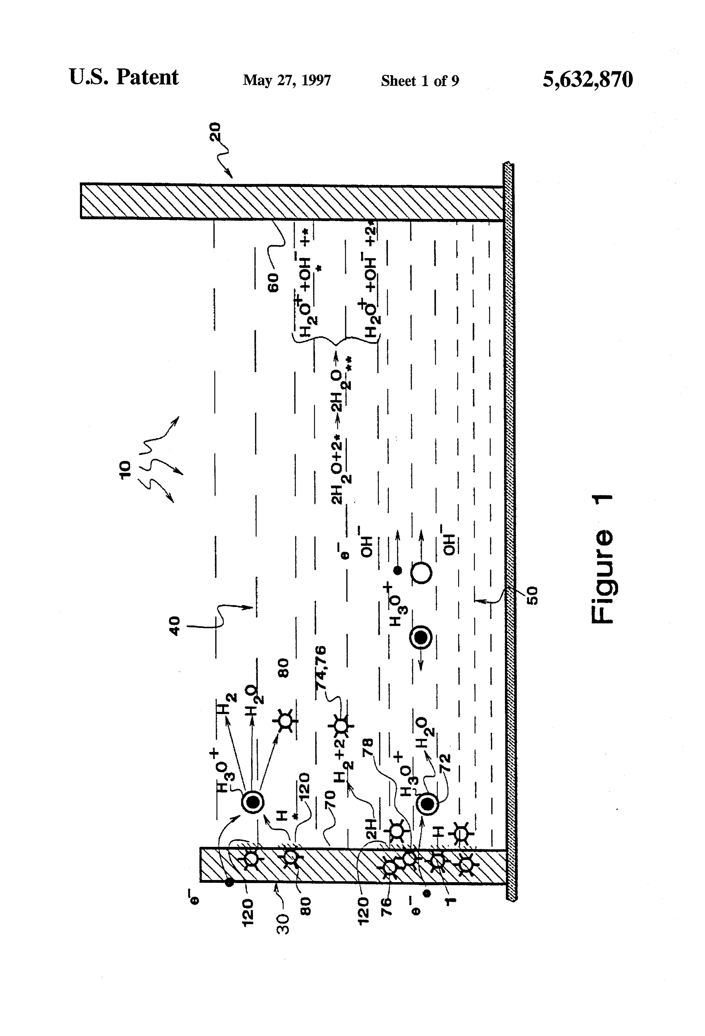
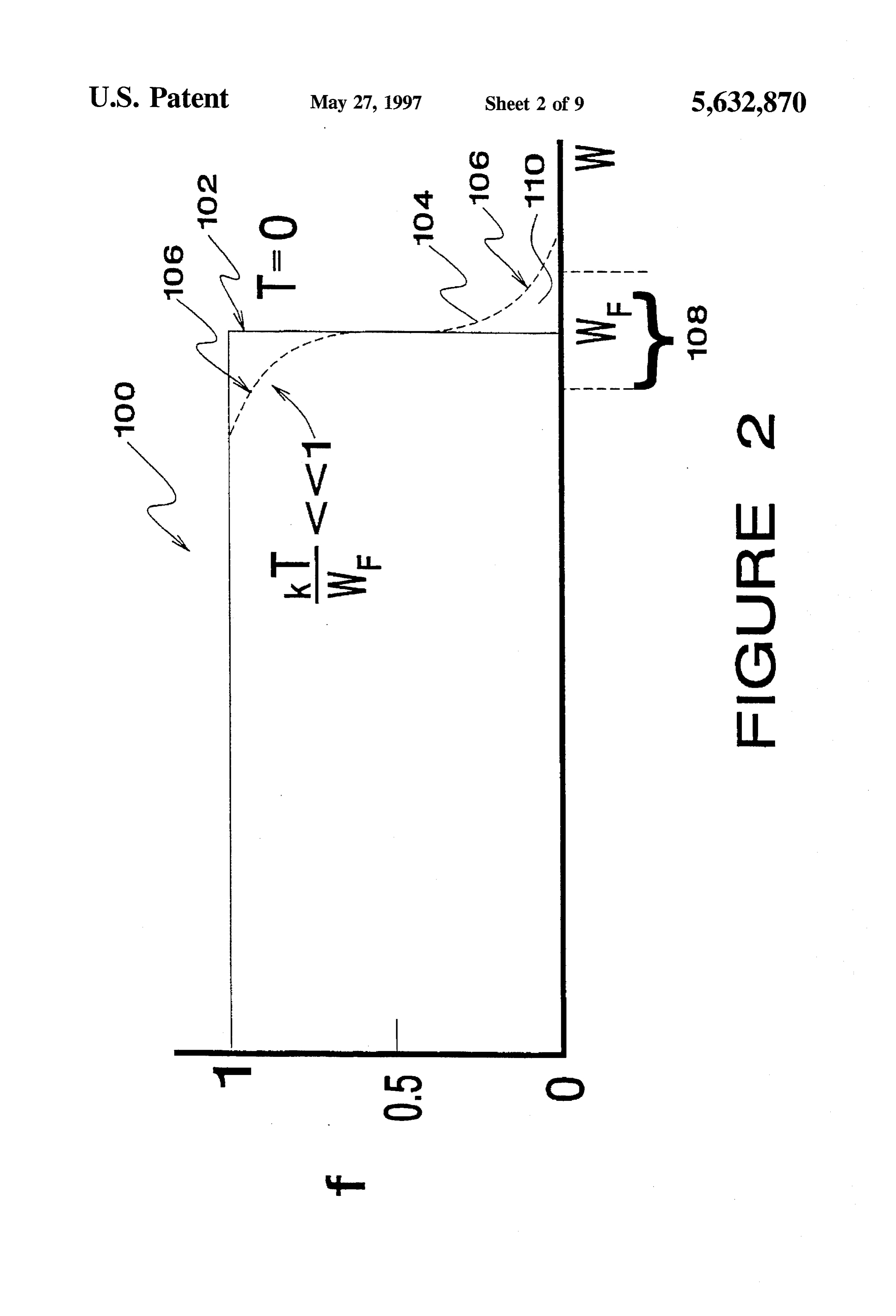
In summary, during operation of the cell, the anode is BRIEF DESCRIPTION OF THE DRAWINGS intensively cooled, and the cathode is generally moderately 15 FIG. 1 is a schematic illustration of a postulated electro heated. The mechanical parts of the invention comprise an chemical and physical process taking place in an electrolytic electrolytic cell having (1) an anode which is an cell involving an anode where catalysis is used to dissociate endothermic, catalytic reducer of water and which is in water and a cathode where hydrogen gas is generated. efficient thermal communication with the environment Sur rounding the cell, (2) a liquid, aqueous or hydrogen 20 FIG. 2 is a plot of a known Fermi–Dirac distribution providing, electrolyte interposed between the anode and a function, showing a graph for electron energy distribution at cathode which has a low voltage potential barrier at the absolute zero (solid line) and a variation of the graph for a electrolyte interfacing surface of the cathode, (3) a cathode non-zero temperature (dashed line).
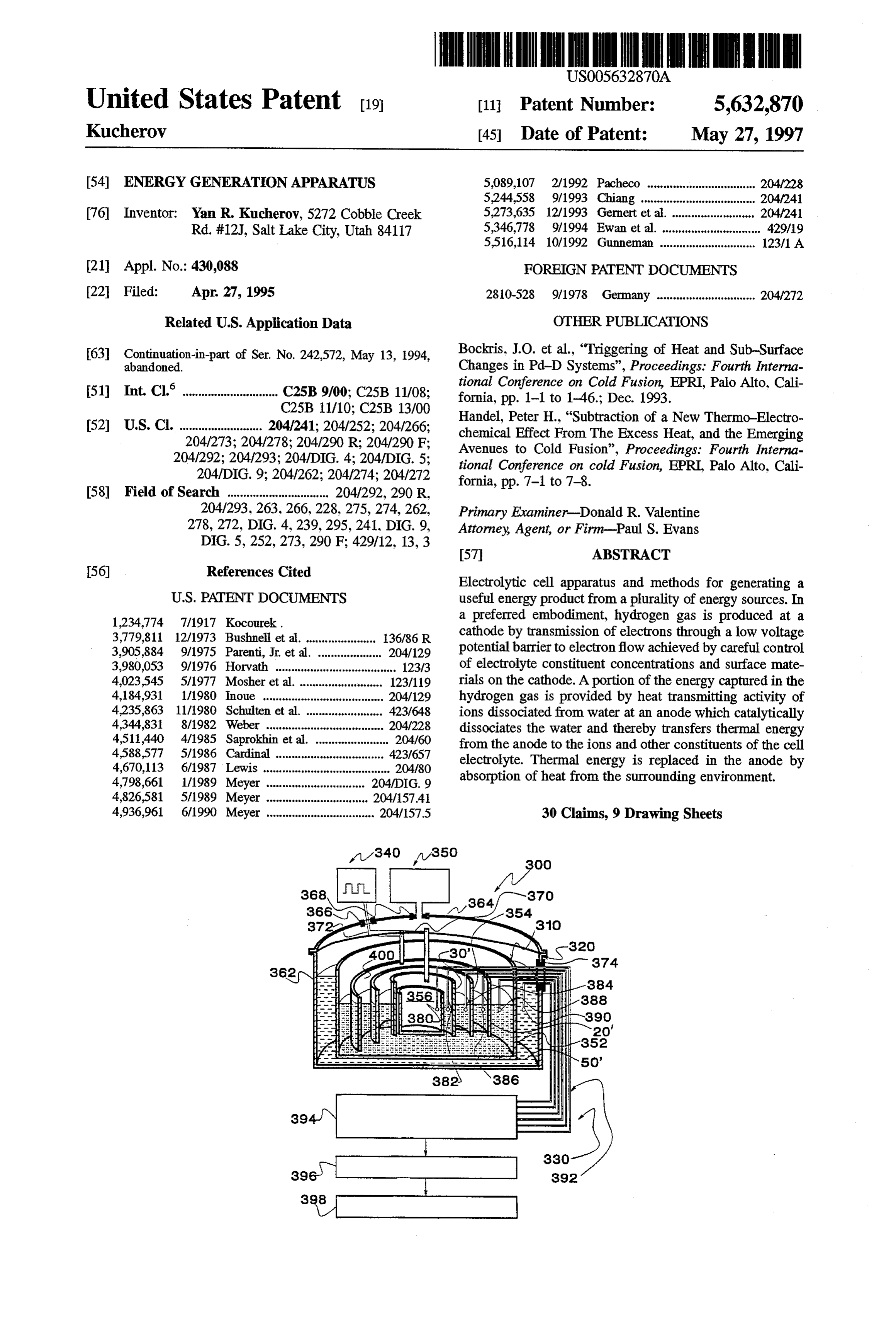
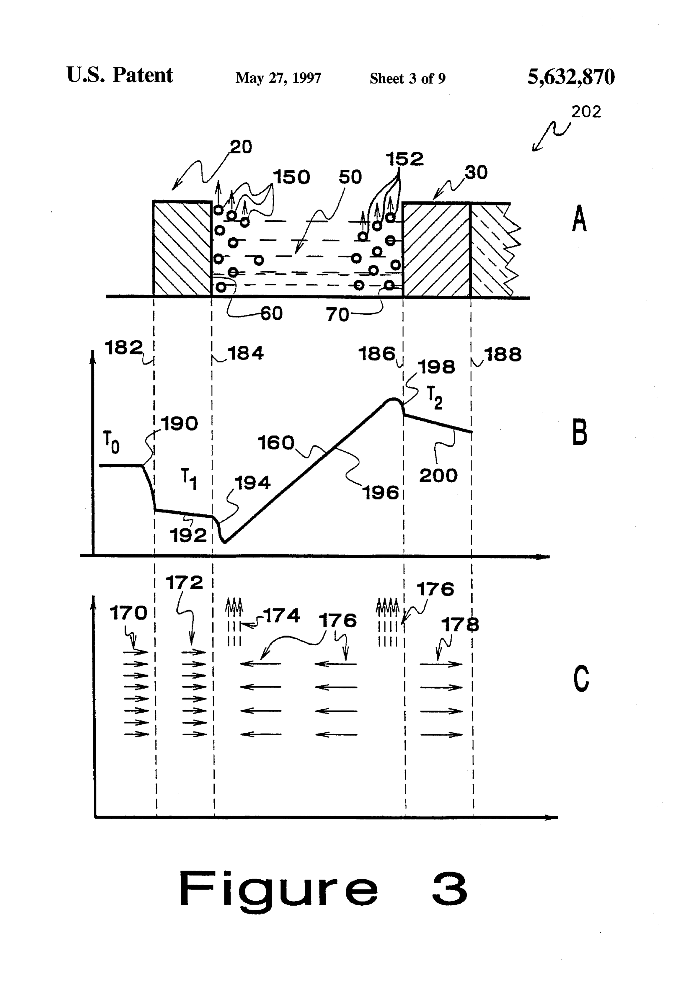
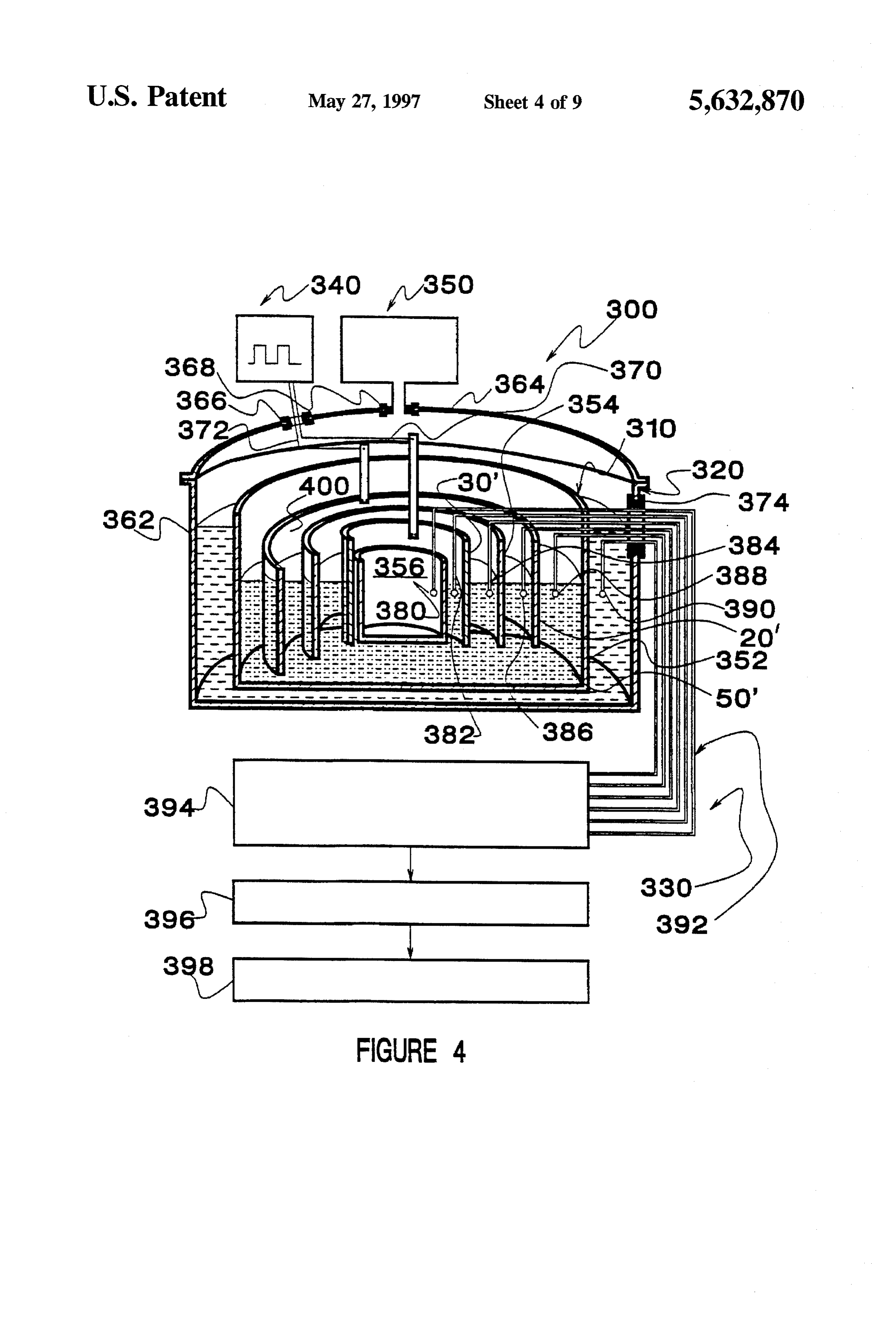
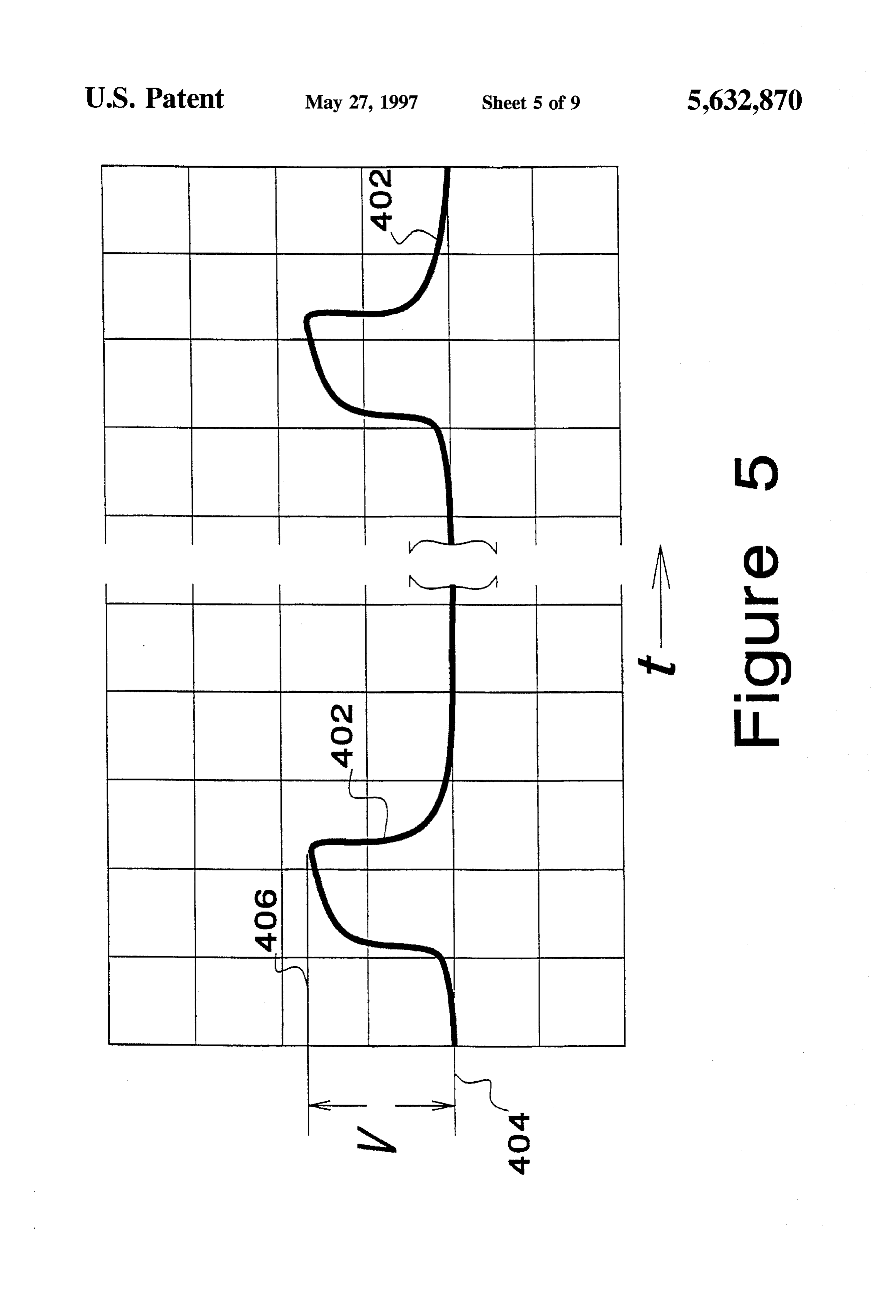
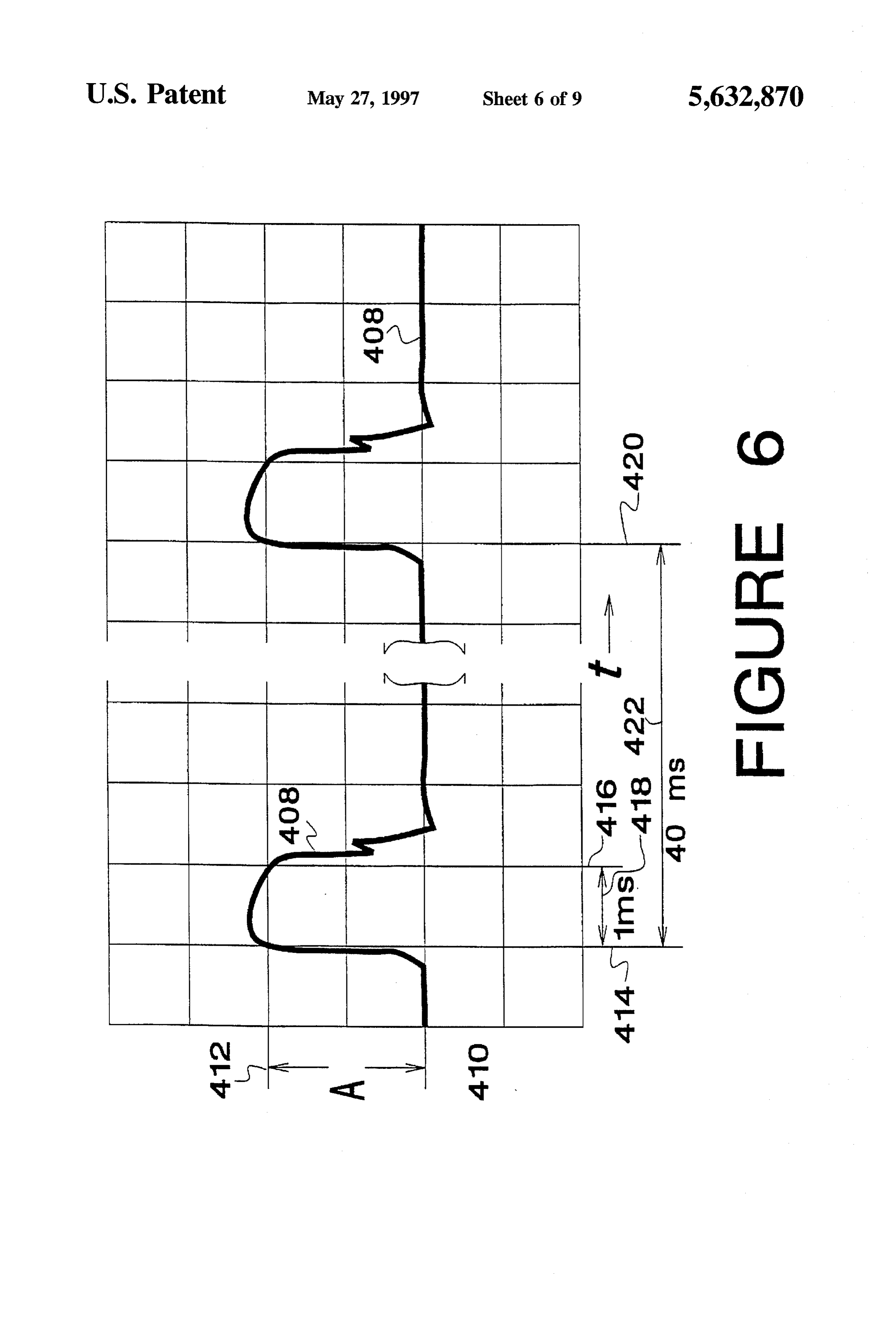
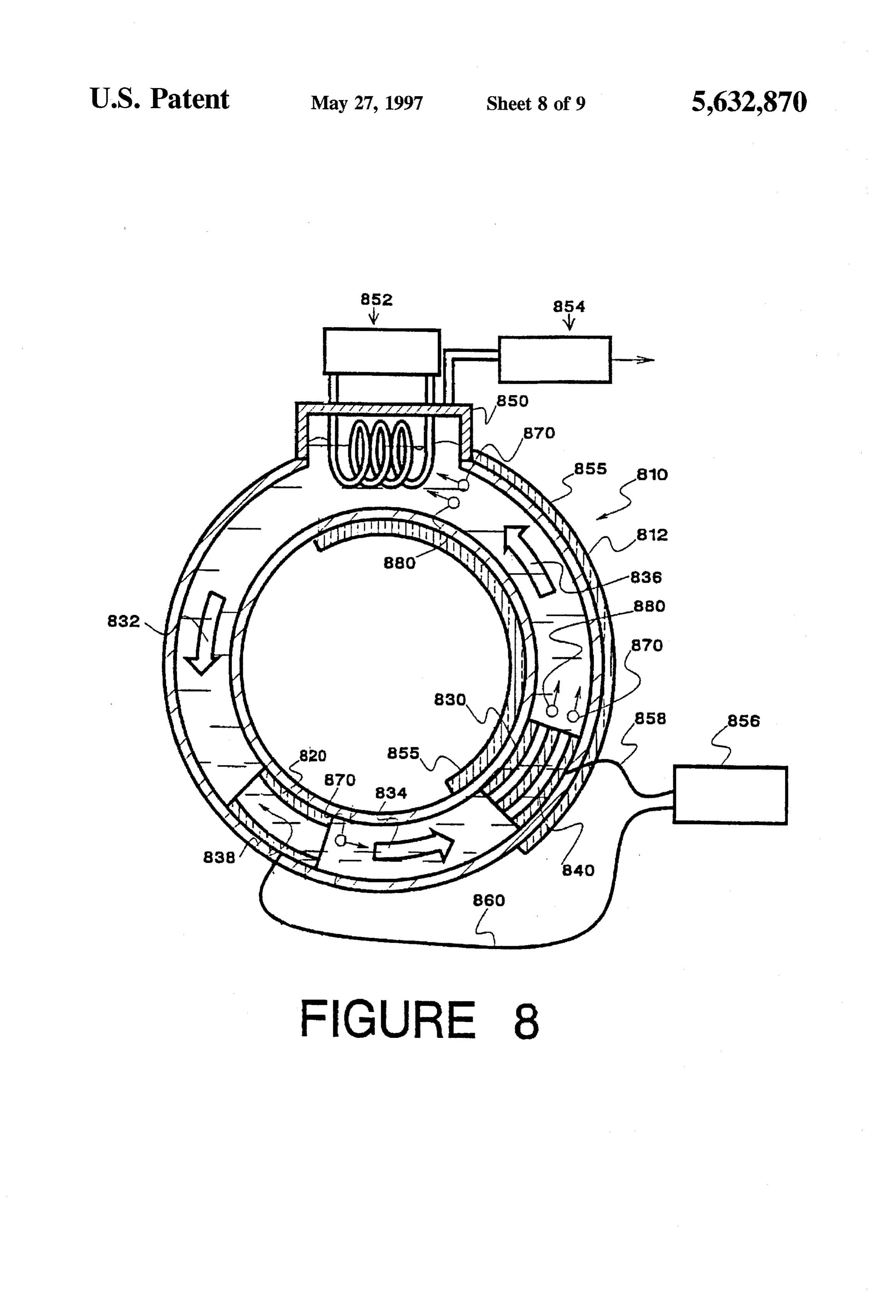
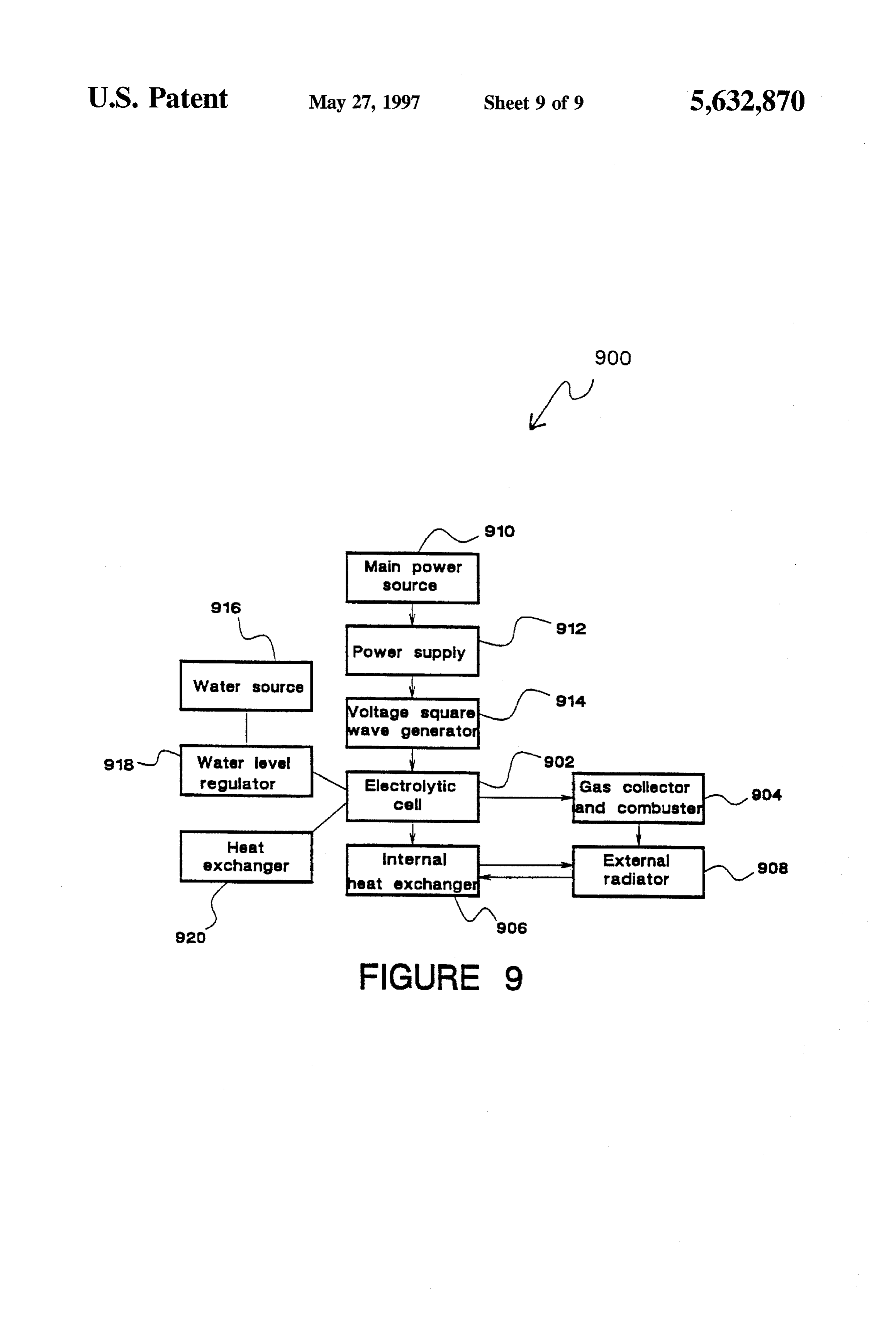
having an electrolyte interacting surface which is covered by 25 FIG. 3 is a cross-sectional view of an exemplary electro a material which cooperatively exhibits the low voltage lytic cell of the instant invention comprising three parts: “A” surface potential barrier relative to the electrolyte, (4) a schematically shows the relation of the electrodes to the source of a pulsed electrical voltage applied between the surrounding environment and gas release; "B" is a plot of the cathode and anode, the voltage having appropriate magni temperature relative to space within and without the cell; tude and frequency characteristics to overcome the low and “C” illustrates the heat flow within the cell. voltage potential barrier and (5) a spacer disposed within the 30 FIG. 4 is a cross-sectional view of an experimental electrolyte and interposed between the cathode and anode to configuration of a test cell with connecting functional blocks raise the thermal resistance between the cathode and anode to represent a complete test system. and pass ions between the electrodes while steering hydro gen gas emitted from the cathode to a hydrogen gas collec 35 FIG. 5 is a plot of a voltage waveform. tOr. FIG. 6 is a plot of an amperage waveform associated with Accordingly, it is a primary object of the present invention the voltage waveform of FIG. 5.
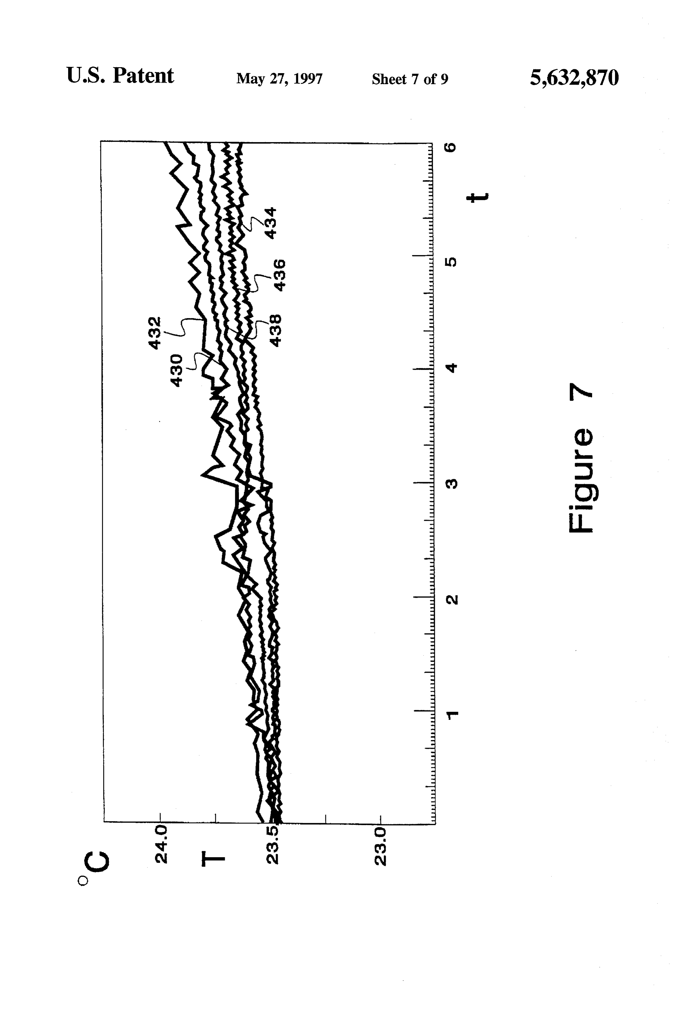
to provide an aqueous electrolytic cell which operates as a FIG. 7 is a plot of a plurality of measured temperatures thermal pump, producing hydrogen gas and thermal energy, derived through operation of a cell.
whereby at least a portion of the energy is derived from heat 40 FIG. 8 is a lateral section of a cell with schematic blocks inherent in an environment surrounding the cell. of devices associated with the cell. Another primary object of the present invention is to FIG. 9 is a block diagram of a heat pump heater system. provide an aqueous electrolytic cell which catalytically dissociates water into positive and negative ions while DESCRIPTION OF THE PREFERRED cooling the anode of the cell. 45
EMBODIMENT
A further object of the present invention is to provide an aqueous electrolytic cell which has a low voltage potential theInsegment this description, the term proximal is used to indicate of the device normally closest to the object of barrier between the cell electrolyte and the cathode surface the sentence describing its position. The term distal refers to which interfaces with the electrolyte. the other end. Reference is now made to the embodiments Additionally, it is an object of the present invention to 50 illustrated in FIGS. 1-9 wherein like numerals are used to provide an aqueous electrolytic cell which has a low elec designate like parts throughout. In places within this speci trical resistance between the anode and the cathode while fication where it is preferable to indicate that parts have having a high thermal resistance. similar function, but not identical mechanical and material A further object of the present invention is to provide an configuration, the same numerals with primes added are electrolytic cell and highly effective electrolytic process 55 used to improve ease of reference.
with equivalent thermal energy yield well in excess of the Technical Principles and Background amount of input electric energy consumed to operate the Conventional approaches used in the production of hydro cell. gen and other electrolytically produced fuels have essen Another object of the present invention is to provide an tially been constrained to devices and methods which have electrolytic cell and a highly effective electrolytic process 60 depended upon strict adherence to Faraday's Law (i.e. which pump heat available from a surrounding environment wherein for a given amount of electrical charge utilized to to a dissociated portion of water within the cell and which drive the electrolysis process, a fixed, predictable maximum effectively transport and deliver at least a portion of that heat volume of gas is expected to be generated, assuming 100% to hydrogen and oxygen gas produced by the cell. efficiency of device operation.) This limitation has almost Aprimary object of the presentinventionis to increase the 65 universally led to the conclusion that heretofore known effectiveness of cell operation by high frequency electro techniques for electrochemical generation of hydrogen are magnetic agitation of the catalytic features of the metal. impractical as a method of extracting hydrogen fuel from
Page 13
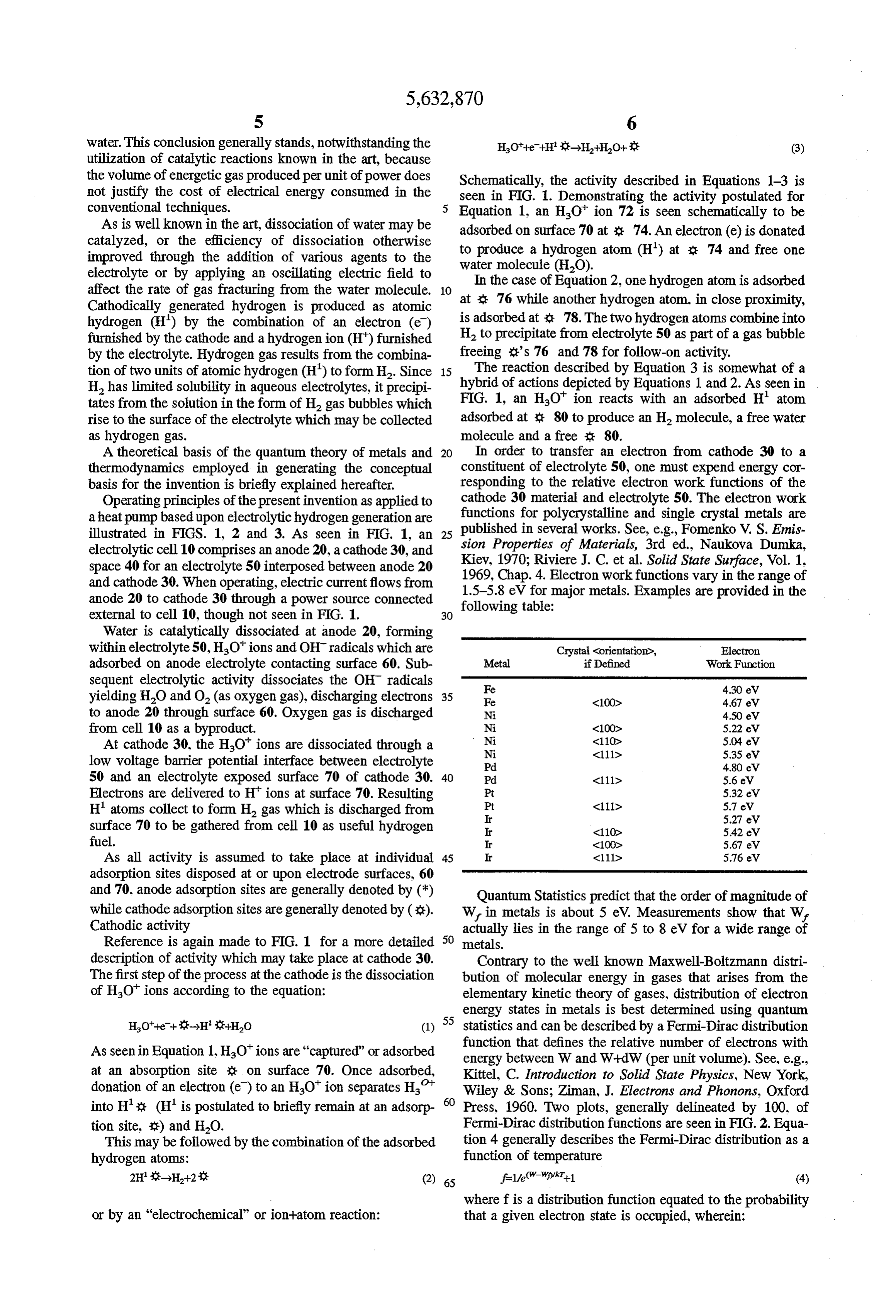
water. This conclusion generally stands, notwithstanding the HO'--e-Hit-HHO- (3) utilization of catalytic reactions known in the art, because the volume of energetic gas produced per unit of power does Schematically, the activity described in Equations 1-3 is not justify the cost of electrical energy consumed in the seen in FIG. 1. Demonstrating the activity postulated for conventional techniques. Equation 1, an HO ion 72 is seen schematically to be As is well known in the art, dissociation of water may be adsorbed on surface 70 at 3: 74. An electron (e) is donated catalyzed, or the efficiency of dissociation otherwise improved through the addition of various agents to the to produce a hydrogen atom (H) at : 74 and free one water molecule (HO).
electrolyte or by applying an oscillating electric field to affect the rate of gas fracturing from the water molecule. at x 76case
In the while of Equation 2, one hydrogen atom is adsorbed another hydrogen atom, in close proximity,
Cathodically generated hydrogen is produced as atomic hydrogen (H) by the combination of an electron (e) is adsorbed at : 78. The two hydrogenatoms combine into furnished by the cathode and a hydrogenion (H) furnished H2 to precipitate from electrolyte 50 as part of a gas bubble by the electrolyte. Hydrogen gas results from the combina freeing :'s 76 and 78 for follow-on activity. tion of two units of atomic hydrogen (H) to form H. Since 15 hybrid The reaction described by Equation 3 is somewhat of a H has limited solubility in aqueous electrolytes, it precipi of actions depicted by Equations 1 and 2. As seen in tates from the solution in the form of H gas bubbles which FIG. 1, an HO ion reacts with an adsorbed H atom rise to the surface of the electrolyte which may be collected adsorbed at 80 to produce an H molecule, a free water as hydrogen gas. molecule and a free : 80.
A theoretical basis of the quantum theory of metals and 20 In order to transfer an electron from cathode 30 to a thermodynamics employed in generating the conceptual constituent of electrolyte 50, one must expend energy cor basis for the invention is briefly explained hereafter. responding to the relative electron work functions of the Operating principles of the present invention as applied to cathode 30 material and electrolyte 50. The electron work aheat pump based upon electrolytic hydrogen generation are functions for polycrystalline and single crystal metals are illustrated in FIGS. 1, 2 and 3. As seen in FIG. 1, an 25 published in several works. See, e.g., Fomenko V. S. Emis electrolytic cell 10 comprises an anode 20, a cathode 30, and sion Properties of Materials, 3rd ed., Naukova Dumka, space 40 for an electrolyte 50 interposed between anode 20 Kiev, Chap. 1970; Riviere J. C. et al. Solid State Surface, Vol. 1, and cathode 30. When operating, electric current flows from 1969, 4. Electron workfunctions vary in the range of anode 20 to cathode 30 through a power source connected following table:major metals. Examples are provided in the
external to cell 10, though not seen in FIG. 1. 30
Water is catalytically dissociated at anode 20, forming within electrolyte 50, HOions and OH radicals which are Crystal Corientation>, Electron adsorbed on anode electrolyte contacting surface 60. Sub Metal if Defined Work Function sequent electrolytic activity dissociates the OH radicals Fe 430 eV yielding HO and O (as oxygen gas), discharging electrons 35 Fe K100> 4.67 eV to anode 20 through surface 60. Oxygen gas is discharged N 450 eV from cell 10 as a byproduct. N
At cathode 30, the HO ions are dissociated through a N k111 5.35 eV low voltage barrier potential interface between electrolyte Pd 480 eV 50 and an electrolyte exposed surface 70 of cathode 30. 40 Pd (111) 5.6 eV Electrons are delivered to Hions at surface 70. Resulting Pt 5.32 eV H' atoms collect to form H gas which is discharged from Pt
surface 70 to be gathered from cell 10 as useful hydrogen r (110 5.42 eW fuel. r a100 5.67 eV As all activity is assumed to take place at individual 45 r C111 5.76 eV adsorption sites disposed at or upon electrode surfaces, 60 and 70, anode adsorption sites are generally denoted by (*) Quantum Statistics predict that the order of magnitude of while cathode adsorption sites are generally denoted by (*). W, in metals is about 5 eV. Measurements show that W, Cathodic activity actually lies in the range of 5 to 8 eV for a wide range of Reference is again made to FIG. 1 for a more detailed 50 metals.
description of activity which may take place at cathode 30. Contrary to the well known Maxwell-Boltzmann distri The first step of the process at the cathode is the dissociation bution of molecular energy in gases that arises from the of HO' ions according to the equation: elementary kinetic theory of gases, distribution of electron energy states in metals is best determined using quantum
HO-et--->H-HO (1) 55 statistics and can be described by a Fermi–Dirac distribution function that defines the relative number of electrons with
As seen in Equation 1. HO" ions are "captured” or adsorbed energy between W and W--dW (per unit volume). See, e.g., at an absorption site - on surface 70. Once adsorbed, Kittel, C. Introduction to Solid State Physics, New York, donation of an electron (e) to an HO" ion separates H. Wiley & Sons; Ziman, J. Electrons and Phonons, Oxford into H': (H" is postulated to briefly remain at an adsorp Press, 1960. Two plots, generally delineated by 100, of tion site, E) and H2O. Fermi-Dirac distribution functions are seen in FIG.2. Equa This may be followed by the combination of the adsorbed tion 4 generally describes the Fermi–Dirac distribution as a hydrogen atoms: function of temperature 2Hi-H+2 it (2) 65 f 1/(w-Wikt-1 (4) where f is a distribution function equated to the probability or by an "electrochemical” or ion-atom reaction: that a given electron state is occupied, wherein:
Page 14
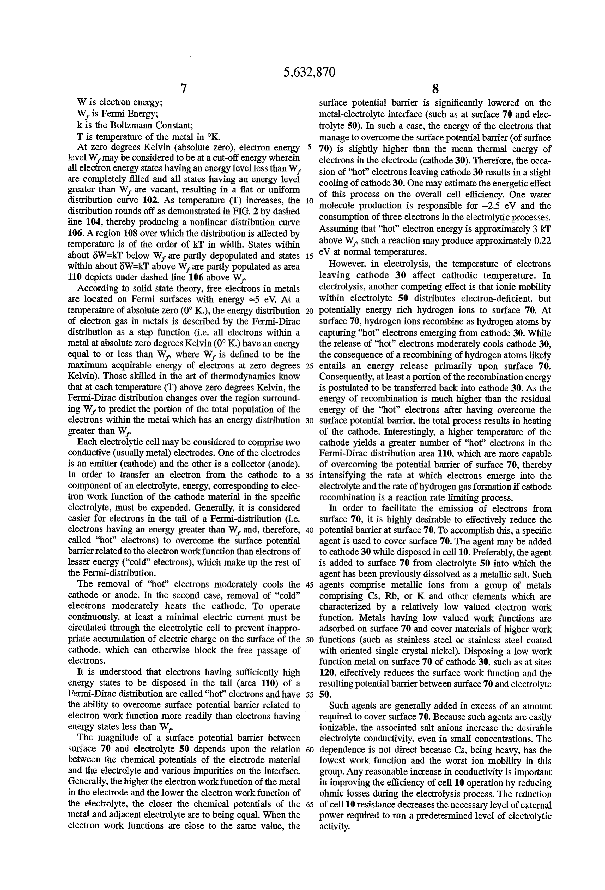
W is electron energy; surface potential barrier is significantly lowered on the Wis Fermi Energy; metal-electrolyte interface (such as at surface 70 and elec k is the Boltzmann Constant; trolyte 50). In such a case, the energy of the electrons that T is temperature of the metal in K. manage to overcome the surface potential barrier (of surface At Zero degrees Kelvin (absolute zero), electron energy 5 70) is slightly higher than the mean thermal energy of level Wmay be considered to be at a cut-off energy wherein electrons in the electrode (cathode 30). Therefore, the occa all electron energy states having an energy levelless than W. sion of “hot” electrons leaving cathode 30 results in a slight are completely filled and all states having an energy level cooling of cathode 30. One may estimate the energetic effect greater than W are vacant, resulting in a flat or uniform of this process on the overall cell efficiency. One water distribution curve 102. As temperature (T) increases, the O molecule production is responsible for -2.5 eV and the distribution rounds off as demonstrated in FIG. 2 by dashed consumption of three electrons in the electrolytic processes. line 104, thereby producing a nonlinear distribution curve Assuming that "hot" electron energy is approximately 3 kT 106. A region 108 over which the distribution is affected by temperature is of the order of kT in width. States within above Wa such a reaction may produce approximately 0.22 about 8W=kT below W are partly depopulated and states eVHowever, 5 at normal temperatures.
in electrolysis, the temperature of electrons within about 8W=kT above Ware partly populated as area leaving cathode 30 affect cathodic temperature. In 110 depicts under dashed line 106 above W.
According to solid state theory, free electrons in metals electrolysis, another competing effect is that ionic mobility are located on Fermi surfaces with energy s5 eV. At a within electrolyte 50 distributes electron-deficient, but temperature of absolute zero (0°K.), the energy distribution 20 potentially energy rich hydrogen ions to surface 70. At of electron gas in metals is described by the Fermi-Dirac surface 70, hydrogen ions recombine as hydrogen atoms by distribution as a step function (i.e. all electrons within a capturing "hot" electrons emerging from cathode 30. While metal at absolute zero degrees Kelvin (0°K.) have an energy the release of “hot” electrons moderately cools cathode 30, equal to or less than W, where W is defined to be the the consequence of a recombining of hydrogen atoms likely maximum acquirable energy of electrons at Zero degrees 25 entails an energy release primarily upon surface 70. Kelvin). Those skilled in the art of thermodynamics know Consequently, at least a portion of the recombination energy that at each temperature (T) above zero degrees Kelvin, the is postulated to be transferred back into cathode 30. As the Fermi-Dirac distribution changes over the region surround energy of recombination is much higher than the residual ing W to predict the portion of the total population of the energy of the “hot” electrons after having overcome the electrons within the metal which has an energy distribution 30 surface potential barrier, the total process results in heating greater than W. of the cathode. Interestingly, a higher temperature of the Each electrolytic cell may be considered to comprise two cathode yields a greater number of “hot” electrons in the conductive (usually metal) electrodes. One of the electrodes Fermi-Dirac distribution area 110, which are more capable is an emitter (cathode) and the other is a collector (anode). of overcoming the potential barrier of surface 70, thereby In order to transfer an electron from the cathode to a 35 intensifying the rate at which electrons emerge into the component of an electrolyte, energy, corresponding to elec electrolyte and the rate of hydrogen gas formation if cathode tron work function of the cathode material in the specific recombination is a reaction rate limiting process. electrolyte, must be expended. Generally, it is considered In order to facilitate the emission of electrons from easier for electrons in the tail of a Fermi-distribution (i.e. surface 70, it is highly desirable to effectively reduce the electrons having an energy greater than W, and, therefore, 40 potential barrier at surface 70. To accomplish this, a specific called "hot" electrons) to overcome the surface potential agent is used to cover surface 70. The agent may be added barrier related to the electron workfunction than electrons of to cathode 30 while disposed in cell 10. Preferably, the agent lesser energy ("cold" electrons), which make up the rest of is added to surface 70 from electrolyte 50 into which the the Fermi-distribution. agent has been previously dissolved as a metallic salt. Such The removal of “hot” electrons moderately cools the 45 agents comprise metallic ions from a group of metals cathode or anode. In the second case, removal of "cold” comprising Cs, Rb, or K and other elements which are electrons moderately heats the cathode. To operate characterized by a relatively low valued electron work continuously, at least a minimal electric current must be function. Metals having low valued work functions are circulated through the electrolytic cell to prevent inappro adsorbed on surface 70 and cover materials of higher work priate accumulation of electric charge on the surface of the 50 functions (such as stainless steel or stainless steel coated cathode, which can otherwise block the free passage of with oriented single crystal nickel). Disposing a low work electrons. function metal on surface 70 of cathode 30, such as at sites It is understood that electrons having sufficiently high 120, effectively reduces the surface work function and the energy states to be disposed in the tail (area 110) of a resulting potential barrier between surface 70 and electrolyte Fermi-Dirac distribution are called "hot' electrons and have 55 50.
the ability to overcome surface potential barrier related to Such agents are generally added in excess of an amount electron work function more readily than electrons having required to cover surface 70. Because such agents are easily energy states less than W. ionizable, the associated salt anions increase the desirable The magnitude of a surface potential barrier between electrolyte conductivity, even in small concentrations. The surface 70 and electrolyte 50 depends upon the relation dependence is not direct because Cs, being heavy, has the between the chemical potentials of the electrode material lowest work function and the worst ion mobility in this and the electrolyte and various impurities on the interface. group. Any reasonable increase in conductivity is important Generally, the higher the electron workfunction of the metal in improving the efficiency of cell 10 operation by reducing in the electrode and the lower the electron workfunction of ohmic losses during the electrolysis process. The reduction the electrolyte, the closer the chemical potentials of the 65 of cell 10 resistance decreases the necessary level of external metal and adjacent electrolyte are to being equal. When the power required to run a predetermined level of electrolytic electron work functions are close to the same value, the activity.
Page 15
Anodic activity exchange between the environment and anode 20. The Referring again to FIG. 1, anode 20 is preferably made of excess energy of the cellis derived from heat absorbed from a metal with the ability to catalytically dissociate water, e.g. the surrounding environment which is generally warmer Ni, Pt, Ir, Platinum-nickel alloys, noble metals, nickel than anode 20.
stainless steel, or Pd F.C.C. single crystal with <111D It should be noted that thermodynamic analysis of a crystallographic orientation, or other non-corrosive high closed system does not predict more energy emitted from the electron work function metals like Re or W. and alloys cell than is provided by electrical power delivered to an thereof. A key to the operation of the instant invention as a electrolytic cell. Taking advantage of endothermic cooling thermal pump is that water molecules undergoing catalytic charge of anode 20, resultant heating of cathode 30 and the dis dissociation are endothermic and consume energy from the change,from 10 cell 10 of an energy rich gas from a phase allows the instant invention to operate as an excess catalyst. Further, to maintain a thermal conducting process energy generating heat pump. from anode 20 to ions within electrolyte 50, the thermal conductivity of anode 20 is much greater than the associated thermally isolated from theeffectively, For cell 10 to operate cathode 30 must be thermal conductivity of electrolyte 50. A major causal pro be in efficient thermal communication withandtheanode environment 20 must environment.
cess which is considered to determine a temperature change 15 For increased operational efficiency, it is recommended within anode 20 is expenditure of internal anode 20 heat that care be taken to include the following features in the during water dissociation. design of cell 10:
It is assumed that each catalytic agent has a plurality of 1. Anion permeable membrane interposed between anode catalysis sites, generally denoted by “". At anode 20, water 20 and cathode 30 to reduce convective and other molecules may dissociate as described in the following 20 retrograde heat flow from cathode 30 to anode 20. equations: 2. A relatively small gap between anode 20 and cathode 30 to reduce the ohmic losses to as little as possible.
Such a gap should not be smaller than two electron
O screening radii (Debye radii) in electrolyte 50 space, 25 otherwise normal cell operation will be ruined. A fundamental property of the counterion distribution is
Equations 5 and 6 postulate the use of two catalysis sites for the thickness of the ion atmosphere, determined by the generation of each pair of HO and OH ions. Equation 5 quantity (1/k) called the Debye length or Debye radius. postulates the continued attachment of an OH ion to one 30 1/K has the cgs dimensions of cm, so Khas dimensions catalysis site following dissociation. Equation 6 postulates cm '; K is given by:
the separation of all ions from catalysis sites following 12 dissociation. Other activity may catalytically generate a -( 87NepA
small amount of hydrogen gas but for the most part, reduces hydroxide ions to produce water and oxygen as described by 35 the following equation: in which p is the solvent density, e is the protonic charge (4,803x10'esu), e is the solvent dielectric constant, NA is Avagadro's number, Kris Boltzmann's
It is likely that some exothermic processes of ion recom constant, T is temperature and I is the ionic strength. bination take place on surface 60 of the anode 20. However, 40 It must be kept in mind that the gap must be large any exothermic energy release is not considered to be large enough for liquid to reach the surface of each elec compared to the endothermic processes of catalysis which trode and for gas bubbles created at each electrode also occur on surface 60. Further, some endothermic heat is surface to freely rise from the electrode. In some likely dissipated by oxygen and any other gases bubbling up embodiments, the interelectrode gap may be as low from surface 60. The combined resulting effect of catalytic, 45 as 1 micrometer.
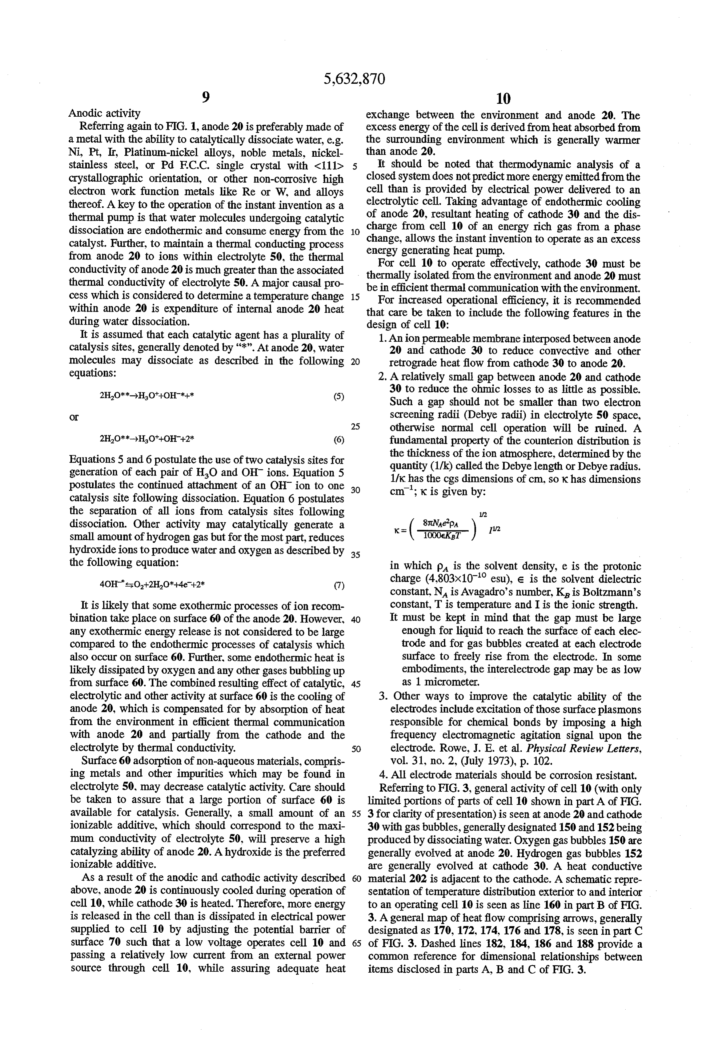
electrolytic and other activity at surface 60 is the cooling of 3. Other ways to improve the catalytic ability of the anode 20, which is compensated for by absorption of heat electrodes include excitation of those surface plasmons from the environment in efficient thermal communication responsible for chemical bonds by imposing a high with anode 20 and partially from the cathode and the frequency electromagnetic agitation signal upon the electrolyte by thermal conductivity. 50 electrode. Rowe, J. E. et al. Physical Review Letters, Surface 60 adsorption of non-aqueous materials, compris vol. 31, no. 2, (July 1973), p. 102. ing metals and other impurities which may be found in 4. All electrode materials should be corrosion resistant. electrolyte 50, may decrease catalytic activity. Care should Referring to FIG. 3, general activity of cell 10 (with only be taken to assure that a large portion of surface 60 is limited portions of parts of cell 10 shown in part A of FIG. available for catalysis. Generally, a Small amount of an 55 3 for clarity of presentation) is seen at anode 20 and cathode ionizable additive, which should correspond to the maxi 30 with gas bubbles, generally designated 150 and 152 being mum conductivity of electrolyte 50, will preserve a high produced by dissociating water. Oxygen gas bubbles 150 are catalyzing ability of anode 20. A hydroxide is the preferred generally evolved at anode 20. Hydrogen gas bubbles 152 ionizable additive. are generally evolved at cathode 30. A heat conductive As a result of the anodic and cathodic activity described material 202 is adjacent to the cathode. A schematic repre above, anode 20 is continuously cooled during operation of sentation of temperature distribution exterior to and interior cell 10, while cathode 30 is heated. Therefore, more energy to an operating cell 10 is seen as line 160 in part B of FIG. is released in the cell than is dissipated in electrical power 3. A general map of heat flow comprising arrows, generally supplied to cell 10 by adjusting the potential barrier of designated as 170,172,174, 176 and 178, is seen in part C surface 70 such that a low voltage operates cell 10 and 65 of FIG. 3. Dashed lines 182, 184, 186 and 188 provide a passing a relatively low current from an external power common reference for dimensional relationships between source through cell 10, while assuring adequate heat items disclosed in parts A, B and C of FIG. 3.
Page 16
Referring again to part B of FIG. 3, line 160 appears to through a heat exchanger results in heating of the anode and comprise a number of distinct segments 190, 192,194,196, thereby adding external energy to the cell. Such added 198, 200. Adjoining segments are continuous. Segment 190 energy provides an opportunity to run a cell at efficiencies represents an environmental temperature external to cell 10 greater than 100% when measured relative to electrical input or at least a temperature of a thermal conductor communi energy. Appropriately designed, such operation of a cell cating environmental temperature to cell 10. Due to the appears to violate the second law of thermodynamics. relatively high thermal conductivity of anode 20 and endot The second law of thermodynamics is not violated hermic activity occurring thereat, segment 190 shows a because a cell absorbing energy from an environment out significant downturn (decrease in temperature) as it becomes side the cell is not a closed system. If the cell were enclosed proximal to a communicating surface of anode 20. Segment 10 in an insulated housing, the second law would be observed, 192 shows only a slight decrease in value as is proceeds and the thermal efficiency would be below unity. from segment 190 to segment 194 due to the relatively high Following is a summary of considerations for maximizing thermal conductivity of anode 20. Segment 194 is represen efficiency of a hydrogen gas electrolytic cell generating tative of anodic activity taking place at or near the surface excess energy. Anode 20 should be a metal having a very 60 of anode 20. Segment 196 plots temperature rise between 15 high water dissociation catalyzing ability, e.g. Ni, Pt, or Pd anode 20 and cathode 30. The shape of segment 196 is single crystal with <111Z orientation. As low a current preferably not linear in a preferred embodiment of cell 10 through cell 10 as possible should be used to prevent ohmic due to a thermal insulator interposed between anode 20 and losses. Easily ionizable additives should be introduced into cathode 30, the character and use of which is discussed in water to form electrolyte 50. Such additives are preferably detail later. Segment 198 represents a relatively small rise in 20 basic salts of K, Rb, or Cs. An external power source temperature at the surface of cathode 30 mainly due to better preferably providing pulsed power of 0.4 to 0.6 volts is thermal conductivity of metal relative to the electrolyte. recommended to run the electrolysis. Assuming that at least Segment 200 is a relatively flat line indicating temperature s02.5 eV energy is released with the combustion of one H. within cathode 30. As seen in FIG. 3A, in some cell designs, molecule, the ratio of electrical energy consumed in the it may be preferable to insulate portions of cathode 30 which 25 operation of cell 10 to thermal energy evolved by burning are not actively used in heat pump operation. released hydrogen may be as high as high as 400-500%. Referring now to heat flow vectors 170-178 shown in This compares very favorably with an expected efficiency of FIG. 3C, as heat flow arrows 170 indicate, during the a closed thermodynamic system in the range of 80-90%. operation of cell 10 a continuous flow of thermal energy is Care should be taken in the design of cell 10 to establish absorbed by anode 20 from the environment. While vectors 30 a low electron work function on the electrode surfaces in 176 indicate a significant tendency for heat flow from combination with as Small of an inter-electrode gap as cathode 30 to anode 20, placement of a thermal insulator possible. (Theoretically a gap the size of two electron between the electrodes permits most energy to be ionically screening radiuses in the electrolyte would be preferred, transported (via HOf ions) from anode 20 to cathode 30. By however; such a small gap precludes adequate liquid flow this means, a significant portion of that energy is transferred 35 between the electrodes and makes the thermal conductivity to hydrogen bubbles eventually evolved at surface 70 of between electrodes too high.) Therefore, a gap of approxi cathode 30. The resulting overall efficiency of the cell 10 mately 100 microns has been established as the preferred operation, in terms of the electricity consumed and energy in gap to reduce the voltage required to operate cell 10 to a the form of heat and hydrogen gas evolved, may, therefore, fraction of a volt.
be greater than unity. For a clearer understanding of proof of the principle of the The electrolytic cell of this instant invention may also be instant invention, results of an experiment on a test model used as a heat pump. For dissociation of water into hydrogen are summarized in FIGS. 4-7 and described hereafter. As and oxygen gas, a normal electrolytic cell generally consists seen in FIG. 4, a test system 300 comprises a test cell 310 of two metal electrodes immersed in an electrolyte. Oxygen (comprising functional parts similar to cell 10), a container is released at the cell anode and hydrogen is released at the 45 320 for the cell 310, a temperature sensing data reduction cell cathode. The dissociation reaction is generally endot system 330, a source of electrical power 340 and an evolved hermic (heat is consumed) and any recombination is exo gas safety handling system 350. It should be emphasized that thermic (heat is released). Such information is well known this apparatus was constructed expressly to evaluate general in the electrolytic cell art and is described in Eisenberg, D. internal cell operation and was not designed as a preferred et al. Physical Chemistry with Applications to Life Sciences, 50 embodiment for capturing and accomplishing over unity John Wiley, 1979. While these effects are known in the art, heat transfer to a usable hydrogen gas. In this test, cell 310 use of such effects in the design of a heat pump has generally comprised a large beaker 352. An anode 20' and cathode 30' eluded incorporation into an operating heat pump device. were disposed within beaker 352. Interposed between anode By channeling heat flow in a cell, a heat pump can be 20' and cathode 30' was a thermal barrier material 354. A created, wherein heat flow will be channelled from outside 55 centrally disposed beaker 356 was medially disposed inside the cell to the anode from the cathode to an outside site. The the cathode to save the amount of electrode needed for the efficiency of such a device is defined by heat loss in the cell system. An electrolyte 50' provided liquid communication coupled with heat loss to the outer walls of the cell. In a between the interior of beaker 352, anode 20' and cathode thermodynamics sense, if the system is closed, the ceil 30'.
efficiency is generally less than one. However, the system of 60 Cell 310 was medially disposed in container 320. Con this invention may also be considered as an open system. tainer 320 comprised a base part 362 which had the form of Elements which cause the system to be open comprise a hollow cylinder closed at the bottom and a removable top released gas and heat exchanged through the outer walls of 364 which provided a gas tight seal when in place on base the cell. part 362. Top 364 comprised two sealed passage ways 366 As endothermic anodic activity reduces anode 65 and 368. Passage way 366 was used for delivery of electrical temperature, providing a way of communicating heat conductors 370 and 372 from power source 340. Passage derived from an environmental source exterior to the cell way 368 was used for safe disposal of evolved gases at a gas
Page 17
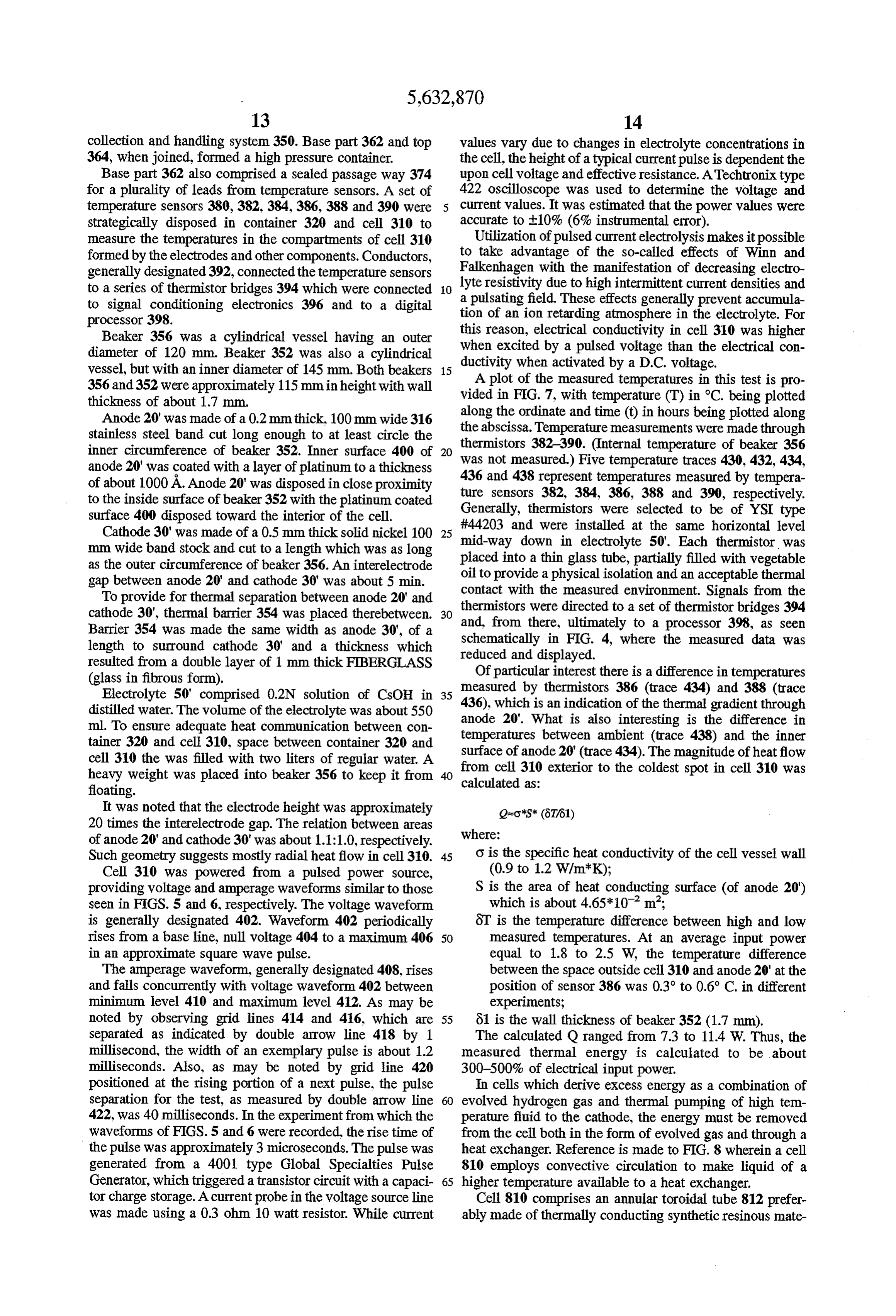
collection and handling system 350. Base part 362 and top values vary due to changes in electrolyte concentrations in 364, when joined, formed a high pressure container. the cell, the height of a typical current pulse is dependent the Base part 362 also comprised a sealed passage way 374 upon cell voltage and effective resistance. ATechtronix type for a plurality of leads from temperature sensors. A set of 422 oscilloscope was used to determine the voltage and temperature sensors 380,382, 384, 386, 388 and 390 were current values. It was estimated that the power values were strategically disposed in container 320 and cell 310 to accurate to t10% (6% instrumental error).
measure the temperatures in the compartments of cell 310 Utilization of pulsed current electrolysis makes it possible formed by the electrodes and other components. Conductors, to take advantage of the so-called effects of Winn and generally designated 392, connected the temperature sensors Falkenhagen with the manifestation of decreasing electro to a series of thermistor bridges 394 which were connected 10 lyte resistivity due to high intermittent current densities and a pulsating field. These effects generally prevent accumula to signal conditioning electronics 396 and to a digital tion of an ion retarding atmosphere in the electrolyte. For processor 398.
Beaker 356 was a cylindrical vessel having an outer this reason, electrical conductivity in cell 310 was higher diameter of 120 mm. Beaker 352 was also a cylindrical when excited by a pulsed voltage than the electrical con vessel, but with an inner diameter of 145 mm. Both beakers 15 ductivity when activated by a D.C. voltage. 356 and 352 were approximately 115mm in height with wall vided A plot of the measured temperatures in this test is pro thickness of about 1.7 mm. in FIG. 7, with temperature (T) in C. being plotted along
Anode 20' was made of a 0.2mm thick, 100mm wide 316 the abscissa. the ordinate and time (t) in hours being plotted along stainless steel band cut long enough to at least circle the Temperature measurements were made through inner circumference of beaker 352. Inner surface 400 of 20 thermistors 382-390. (Internal temperature of beaker 356 anode 20' was coated with a layer of platinum to a thickness was 436 not measured.) Five temperature traces 430, 432, 434, and 438 represent temperatures measured by tempera of about 1000A. Anode 20' was disposed in close proximity to the inside surface of beaker 352 with the platinum coated ture sensors 382, 384, 386, 388 and 390, respectively. Generally, thermistors were selected to be of YSI type surface 400 disposed toward the interior of the cell.
Cathode 30' was made of a 0.5 mm thick solid nickel 100 25 #44203 and were installed at the same horizontal level mm wide band stock and cut to a length which was as long placed mid-way down in electrolyte 50'. Each thermistor was as the outer circumference of beaker 356. An interellectrode into a thin glass tube, partially filled with vegetable gap between anode 20 and cathode 30' was about 5 min. oil to provide a physical isolation and an acceptable thermal contact with the measured environment. Signals from the
To provide for thermal separation between anode 20' and thermistors cathode 30', thermal barrier 354 was placed therebetween. 30 were directed to a set of thermistor bridges 394 Barrier 354 was made the same width as anode 30', of a and, from there, ultimately to a processor 398, as seen length to surround cathode 30' and a thickness which schematically reduced and in FIG. 4, where the measured data was displayed.
resulted from a double layer of 1 mm thick FIBERGLASS Of particular interest there is a difference in temperatures (glass in fibrous form). measured by thermistors 386 (trace 434) and 388 (trace Electrolyte 50' comprised 0.2N solution of CsCH in 35 436), distilled water. The volume of the electrolyte was about 550 anodewhich 20'.
is an indication of the thermal gradient through
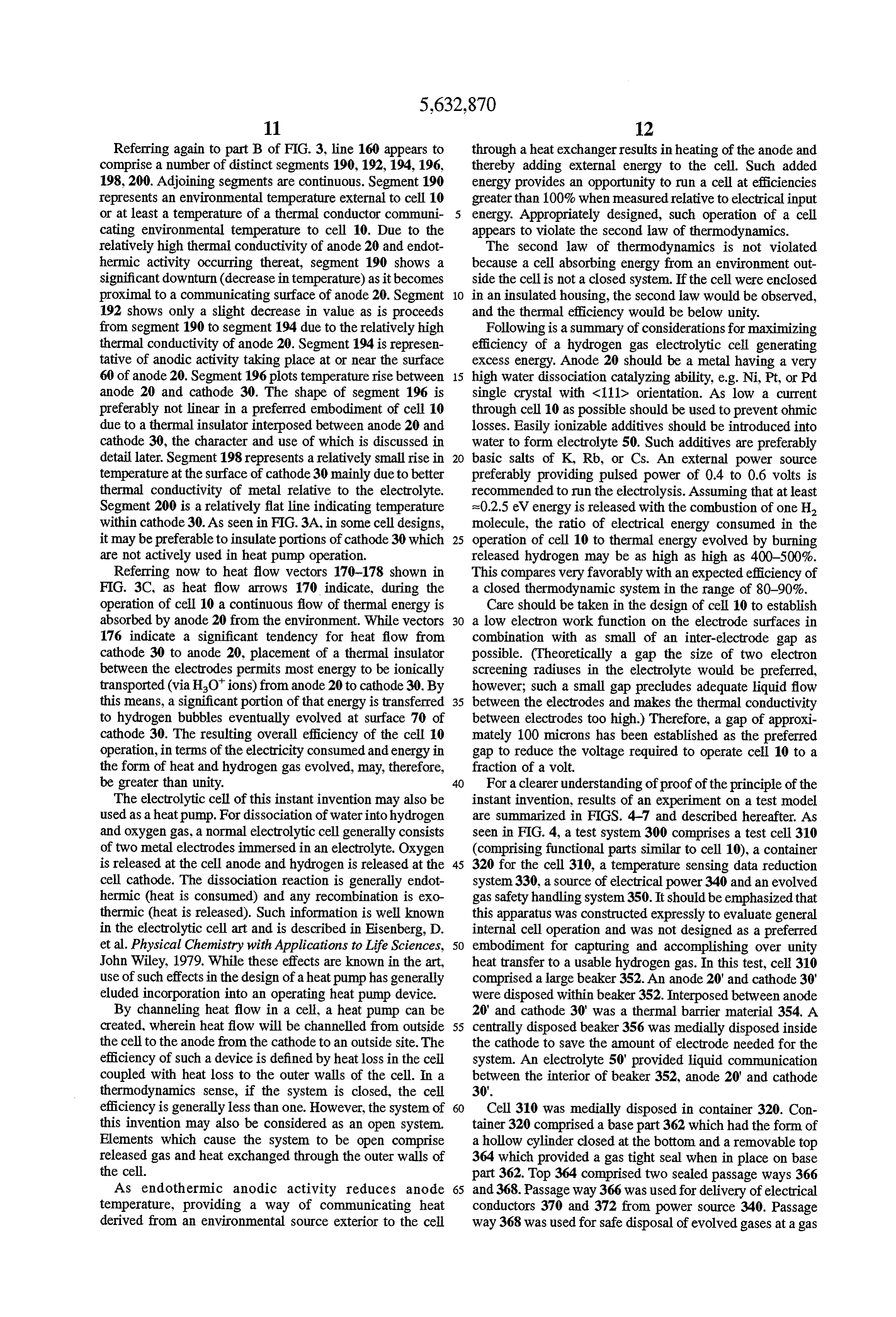
What is also interesting is the difference in ml. To ensure adequate heat communication between con temperatures between ambient (trace 438) and the inner tainer 320 and cell 310, space between container 320 and surface of anode 20' (trace 434). The magnitude of heatflow cell 310 the was filled with two liters of regular water. A from cell 310 exterior to the coldest spot in cell 310 was heavy weight was placed into beaker 356 to keep it from 40 calculated as:
floating.
It was noted that the electrode height was approximately Q-o'S* (8T61) 20 times the interelectrode gap. The relation between areas where:
of anode 20' and cathode 30' was about 1.1:1.0, respectively.
Such geometry suggests mostly radial heatflow in cell 310. 45 o is the specific heat conductivity of the cell vessel wall Cell 310 was powered from a pulsed power source, (0.9 to 1.2 W/m'K);
providing voltage and amperage waveforms similar to those S is the area of heat conducting surface (of anode 20") seen in FIGS. 5 and 6, respectively. The voltage waveform which is about 4.65*10 m;
is generally designated 402. Waveform 402 periodically 8T is the temperature difference between high and low rises from a base line, null voltage 404 to a maximum 406 50 measured temperatures. At an average input power in an approximate square wave pulse. equal to 1.8 to 2.5 W, the temperature difference The amperage waveform, generally designated 408, rises between the space outside cell 310 and anode 20' at the and falls concurrently with voltage waveform 402 between position of sensor 386 was 0.3° to 0.6° C. in different minimum level 410 and maximum level 412. As may be experiments;
noted by observing grid lines 414 and 416, which are 55 61 is the wall thickness of beaker 352 (1.7 mm). separated as indicated by double arrow line 418 by 1 The calculated Q ranged from 7.3 to 11.4 W. Thus, the millisecond, the width of an exemplary pulse is about 1.2 measured thermal energy is calculated to be about milliseconds. Also, as may be noted by grid line 420 300-500% of electrical input power.
positioned at the rising portion of a next pulse, the pulse In cells which derive excess energy as a combination of separation for the test, as measured by double arrow line evolved hydrogen gas and thermal pumping of high tem 422, was 40 milliseconds. In the experiment from which the perature fluid to the cathode, the energy must be removed waveforms of FIGS. 5 and 6 were recorded, the rise time of from the cell both in the form of evolved gas and through a the pulse was approximately 3 microseconds. The pulse was heat exchanger. Reference is made to FIG.8 wherein a cell generated from a 4001 type Global Specialties Pulse 810 employs convective circulation to make liquid of a Generator, which triggered a transistor circuit with a capaci 65 higher temperature available to a heat exchanger. tor charge storage. Acurrent probe in the voltage source line Cell 810 comprises an annular toroidal tube 812 prefer was made using a 0.3 ohm 10 watt resistor. While current ably made of thermally conducting synthetic resinous mate
Page 18
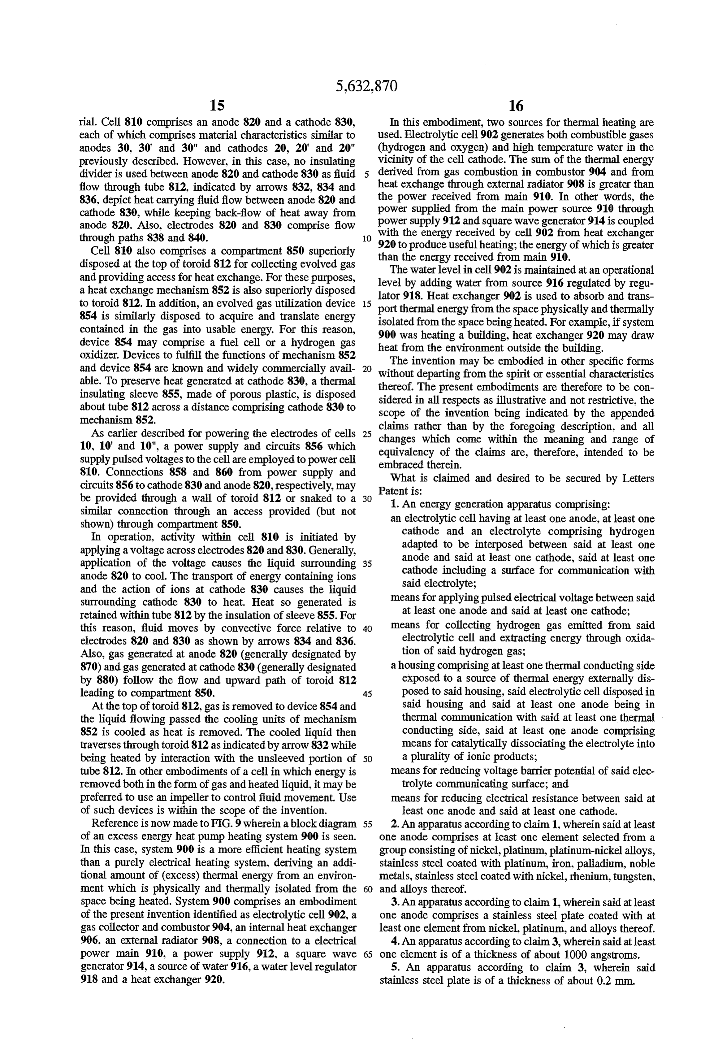
rial. Cell 810 comprises an anode 820 and a cathode 830, In this embodiment, two sources for thermal heating are each of which comprises material characteristics similar to used. Electrolytic cell 902 generates both combustible gases anodes 30, 30' and 30" and cathodes 20, 20' and 20" (hydrogen and oxygen) and high temperature water in the previously described. However, in this case, no insulating vicinity of the cell cathode. The sum of the thermal energy divider is used between anode 820 and cathode 830 as fluid derived from gas combustion in combustor 904 and from flow through tube 812, indicated by arrows 832, 834 and heat exchange through external radiator 908 is greater than 836, depict heat carrying fluid flow between anode 820 and the power received from main 910. In other words, the cathode 830, while keeping back-flow of heat away from power supplied from the main power source 910 through anode 820. Also, electrodes 820 and 830 comprise flow power with supply 912 and square wave generator 914 is coupled the energy received by cell 902 from heat exchanger through paths 838 and 840. 10 920 to produce useful heating; the energy of which is greater
Cell 810 also comprises a compartment 850 superiorly than the energy received from main 910. disposed at the top of toroid 812 for collecting evolved gas and providing access for heat exchange. For these purposes, level bywater
The level in cell 902 is maintained at an operational adding water from source 916 regulated by regu a heat exchange mechanism 852 is also superiorly disposed lator 918. Heat exchanger to toroid 812. In addition, an evolved gas utilization device 15 port thermal energy from the902space is used to absorb and trans 854 is similarly disposed to acquire and translate energy isolated from the space being heated.physically For and thermally example, if system contained in the gas into usable energy. For this reason, 900 was heating a building, heat exchanger 920 may draw device 85.4 may comprise a fuel cell or a hydrogen gas heat from the environment outside the building. oxidizer. Devices to fulfill the functions of mechanism 852 and device 854 are known and widely commercially avail 20 The invention may be embodied in other specific forms able. To preserve heat generated at cathode 830, a thermal without departing from the spirit or essential characteristics insulating sleeve 855, made of porous plastic, is disposed thereof.
sidered
The present embodiments are therefore to be con in all respects as illustrative and not restrictive, the about tube 812 across a distance comprising cathode 830 to scope of the invention being indicated by the appended mechanism 852.
As earlier described for powering the electrodes of cells changes whichthan
claims rather come by the foregoing description, and all within the meaning and range of 10, 10' and 10", a power supply and circuits 856 which equivalency of the claims are, therefore, intended to be supply pulsed voltages to the cell are employed to power cell embraced therein.
810. Connections 858 and 860 from power supply and What is claimed and desired to be secured by Letters circuits 856 to cathode 830 and anode 820, respectively, may Patent is:
be provided through a wall of toroid 812 or snaked to a 30 1. An energy generation apparatus comprising: similar connection through an access provided (but not an electrolytic cell having at least one anode, at least one shown) through compartment 850. cathode and an electrolyte comprising hydrogen In operation, activity within cell 810 is initiated by adapted to be interposed between said at least one applying a voltage across electrodes 820 and 830. Generally, anode and said at least one cathode, said at least one application of the voltage causes the liquid surrounding 35 cathode including a surface for communication with anode 820 to cool. The transport of energy containing ions said electrolyte;
and the action of ions at cathode 830 causes the liquid means for applying pulsed electrical voltage between said surrounding cathode 830 to heat. Heat so generated is retained within tube 812 by the insulation of sleeve 855. For at least one anode and said at least one cathode; this reason, fluid moves by convective force relative to means for collecting hydrogen gas emitted from said electrodes 820 and 830 as shown by arrows 834 and 836. electrolytic cell and extracting energy through oxida Also, gas generated at anode 820 (generally designated by tion of said hydrogen gas;
870) and gas generated at cathode 830 (generally designated a housing comprising at least one thermal conducting side by 880) follow the flow and upward path of toroid 812 exposed to a source of thermal energy externally dis leading to compartment 850. 45 posed to said housing, said electrolytic cell disposed in At the top of toroid 812, gas is removed to device 854 and said housing and said at least one anode being in the liquid flowing passed the cooling units of mechanism thermal communication with said at least one thermal 852 is cooled as heat is removed. The cooled liquid then conducting side, said at least one anode comprising traverses through toroid 812 as indicated by arrow 832 while means for catalytically dissociating the electrolyte into being heated by interaction with the unsleeved portion of 50 a plurality of ionic products; tube 812. In other embodiments of a cell in which energy is means for reducing voltage barrier potential of said elec removed bothin the form of gas and heated liquid, it may be trolyte communicating surface; and preferred to use an impeller to control fluid movement. Use means for reducing electrical resistance between said at of such devices is within the scope of the invention. least one anode and said at least one cathode. Reference is now made to FIG.9 wherein a blockdiagram 55 2. An apparatus according to claim 1, wherein said at least of an excess energy heat pump heating system 900 is seen. one anode comprises at least one element selected from a In this case, system 900 is a more efficient heating system group consisting of nickel, platinum, platinum-nickel alloys, than a purely electrical heating system, deriving an addi stainless steel coated with platinum, iron, palladium, noble tional amount of (excess) thermal energy from an environ metals, stainless steel coated with nickel, rhenium, tungsten, ment which is physically and thermally isolated from the 60 and alloys thereof.
space being heated. System 900 comprises an embodiment 3. An apparatus according to claim 1, wherein said at least of the present invention identified as electrolytic cell 902, a one anode comprises a stainless steel plate coated with at gas collector and combustor 904, an internal heat exchanger least one element from nickel, platinum, and alloys thereof. 906, an external radiator 908, a connection to a electrical 4. An apparatus according to claim3, wherein said at least power main 910, a power supply 912, a square wave 65 one element is of a thickness of about 1000 angstroms. generator 914, a source of water 916, a water level regulator 5. An apparatus according to claim 3, wherein said 918 and a heat exchanger 920. stainless steel plate is of a thickness of about 0.2 mm.
Page 19
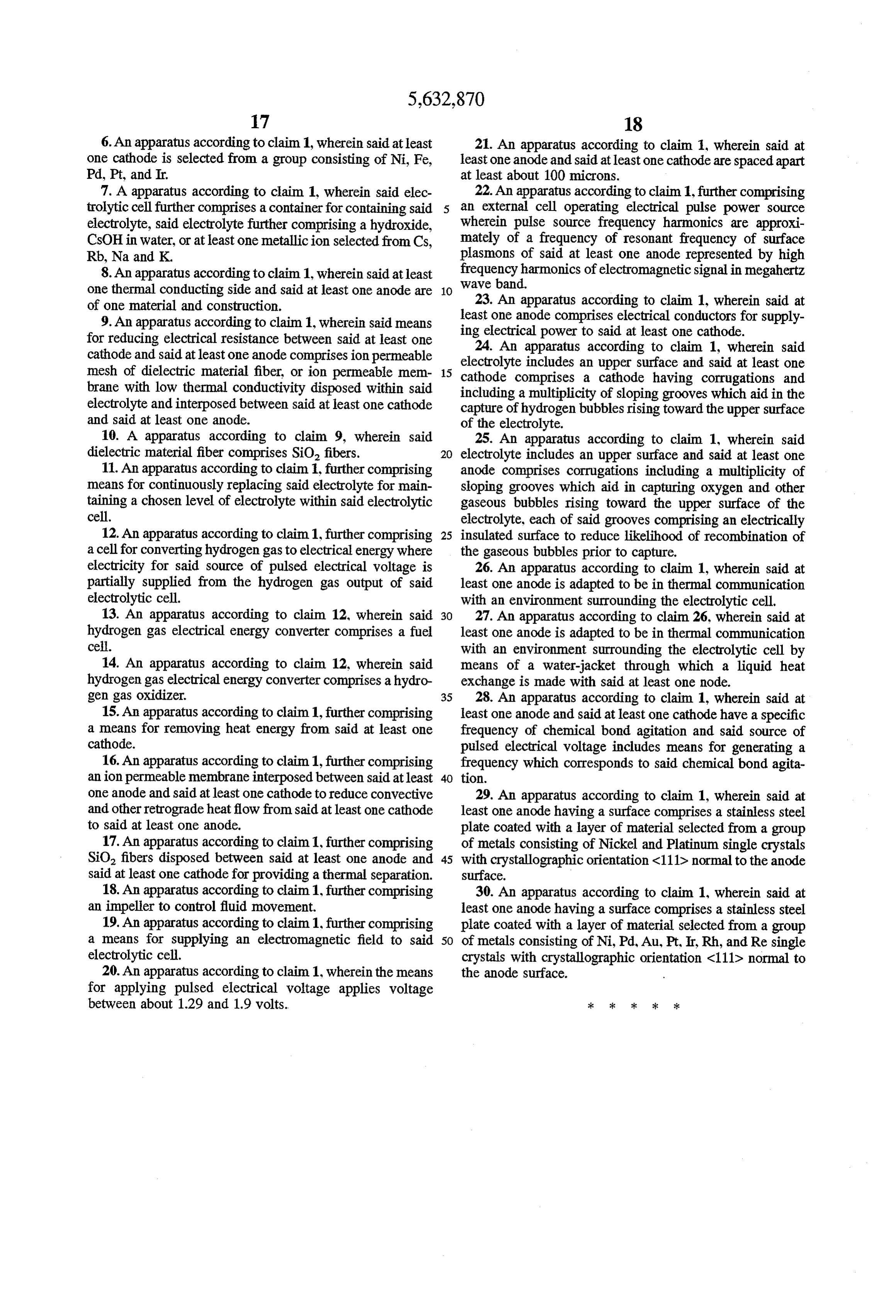
6. An apparatus according to claim 1, wherein said at least 21. An apparatus according to claim 1, wherein said at one cathode is selected from a group consisting of Ni, Fe, least one anode and said at least one cathode are spaced apart Pd, Pt, and Ir. at least about 100 microns.
7. A apparatus according to claim 1, wherein said elec 22. An apparatus according to claim 1, further comprising trolytic cell further comprises a container for containing said an external cell operating electrical pulse power source electrolyte, said electrolyte further comprising a hydroxide, wherein pulse source frequency harmonics are approxi CsCH in water, or at least one metallicion selected from Cs, mately of a frequency of resonant frequency of surface Rb, Na and K. plasmons of said at least one anode represented by high frequency harmonics of electromagnetic signal in megahertz 8. An apparatus according to claim 1, wherein said at least wave one thermal conducting side and said at least one anode are 10 band.
of one material and construction. 23. An apparatus according to claim 1, wherein said at 9. An apparatus according to claim 1, wherein said means least one anode comprises electrical conductors for supply for reducing electrical resistance between said at least one ing24.electrical power to said at least one cathode. cathode and said at least one anode comprisesion permeable electrolyte includes anaccording
An apparatus upper to claim 1, wherein said surface and said at least one mesh of dielectric material fiber, or ion permeable mem 15 cathode comprises a cathode having brane with low thermal conductivity disposed within said including a multiplicity of sloping groovescorrugations and which aid in the electrolyte and interposed between said at least one cathode capture of hydrogen bubbles rising toward the upper surface and said at least one anode. of the electrolyte.
10. A apparatus according to claim 9, wherein said 25. An apparatus according to claim 1, wherein said dielectric material fiber comprises SiO, fibers. 20 electrolyte includes an upper surface and said at least one 11. An apparatus according to claim, further comprising anode comprises corrugations including a multiplicity of means for continuously replacing said electrolyte for main sloping grooves which aid in capturing oxygen and other taining a chosen level of electrolyte within said electrolytic gaseous bubbles rising toward the upper surface of the cell. electrolyte, each of said grooves comprising an electrically 12. An apparatus according to claim 1, further comprising 25 insulated surface to reduce likelihood of recombination of a cell for converting hydrogen gas to electrical energy where the gaseous bubbles prior to capture. electricity for said source of pulsed electrical voltage is 26. An apparatus according to claim 1, wherein said at partially supplied from the hydrogen gas output of said least one anode is adapted to be in thermal communication electrolytic cell. with an environment surrounding the electrolytic cell. 13. An apparatus according to claim 12, wherein said 30 27. An apparatus according to claim 26, wherein said at hydrogen gas electrical energy converter comprises a fuel least one anode is adapted to be in thermal communication cell. with an environment surrounding the electrolytic cell by 14. An apparatus according to claim 12, wherein said means of a water-jacket through which a liquid heat hydrogen gas electrical energy converter comprises a hydro exchange is made with said at least one node. gen gas oxidizer. 35 28. An apparatus according to claim 1, wherein said at 15. An apparatus according to claim 1, further comprising least one anode and said at least one cathode have a specific a means for removing heat energy from said at least one frequency of chemical bond agitation and said source of cathode. pulsed electrical voltage includes means for generating a 16. An apparatus according to claim 1, further comprising frequency which corresponds to said chemical bond agita anion permeable membrane interposed between said at least 40 tion.
one anode and said at least one cathode to reduce convective 29. An apparatus according to claim 1, wherein said at and other retrograde heatflow from said at least one cathode least one anode having a surface comprises a stainless steel to said at least one anode. plate coated with a layer of material selected from a group 17. An apparatus according to claim 1, further comprising of metals consisting of Nickel and Platinum single crystals SiO, fibers disposed between said at least one anode and 45 with crystallographic orientation <111D normal to the anode said at least one cathode for providing a thermal separation. surface.
18. An apparatus according to claim 1, further comprising 30. An apparatus according to claim 1, wherein said at an impeller to control fluid movement. least one anode having a surface comprises a stainless steel 19. An apparatus according to claim 1, further comprising plate coated with a layer of material selected from a group a means for supplying an electromagnetic field to said 50 of metals consisting of Ni, Pd, Au, Pt, Ir, Rh, and Resingle electrolytic cell. crystals with crystallographic orientation <111D normal to 20. An apparatus according to claim 1, wherein the means the anode surface.
for applying pulsed electrical voltage applies voltage between about 1.29 and 1.9 volts.
Page 20
UNITED STATES PATENT ANDTRADEMARK OFFICE
CERTIFICATE OF CORRECTION
INVENTOR(S) : Kucherov it is certified that error appears in the above-identified patent and that said Letters Patent is hereby Corrected as shown below:
Column 11, line 37, after “efficiency of the “ insert --operation of cell 10,--. Column 11, line 38, delete "operation'.
Column 13, line 38, insert “the'after --310,-- (first Occurrence)
Column 13, line 39, delete--the--.
Column 14, line 2, after “dependent' insert-upon--. Column 14, line 3, delete "upon.
Signed and Sealed this
Tenth Day of March, 1998
(a teen BRUCE LEHMAN
Attesting Officer Commissioner of Patents and Trademarks
Provenance
- Collection
- Patents citing this work
- Current assignee
- MicroPower Global Ltd, Baker C P Securities Inc
- Original assignee
- Eneco Inc
- Pages
- 20
- Method
- pdftotext (the PDF's own text layer) + pdftoppm 300dpi page scans
- Patent office record
- patents.google.com →
- Source
- Google Patents citing-documents table
- Inventors
- Yan R. Kucherov; Eneco Inc
- Published
- 1997-05-27
- Transcribed from
- patentimages.storage.googleapis.com →