patent · US5385657
Apparatus for the gasification of water
31 January 1995
Page 1 — bibliographic record
United States Patent (19) 11 Patent Number: 5,385,657 Dungan 45) Date of Patent: Jan. 31, 1995 54 APPARATUS FOR THE GASIFICATION OF 5,244,558 9/1993 Chiang............................ 204/278 X
WATER
Primary Examiner-Donald R. Valentine 76 Inventor: Arthur E. Dungan, P.O. Box 8, Attorney, Agent, or Firm-John M. Harrison Bethany, La. 71007
An apparatus and method for generating hydrogen gas 22 Filed: Sep. 22, 1993 by reacting water and an electrode at high temperature, 51 Int. Cl. ......................... C25B 9/00; C25B 15/08 wherein water is delivered under pressure by a pump in 52 U.S.C. ..................................... 204/228; 204/278 communication with a storage facility or tank in a man 58 Field of Search ................................ 204/275-278, ner forcing the water, at a controlled rate, into a gas 204/229, 228 tight vessel in which a heated electrode is positioned.
56) References Cited An exothermic reaction takes place, whereby the liquid reactant, water, is reduced to hydrogen gas.
A conduit in communication with the produced gas 3,311,097 3/1967 Mittelstaedt .................... 204/278 X outlet of the vessel conducts the hydrogen gas to the 4,361,474 11/1982 Shoaf et al. ..................... 204/278 X predetermined connection for use, whether for combus 5,196,104 3/1993 Munday .......................... 204/278 X tion in an engine, or for industrial use.
5,231,954 8/1993 Stowe ............................. 204/278 X 10 Claims, 2 Drawing Sheets
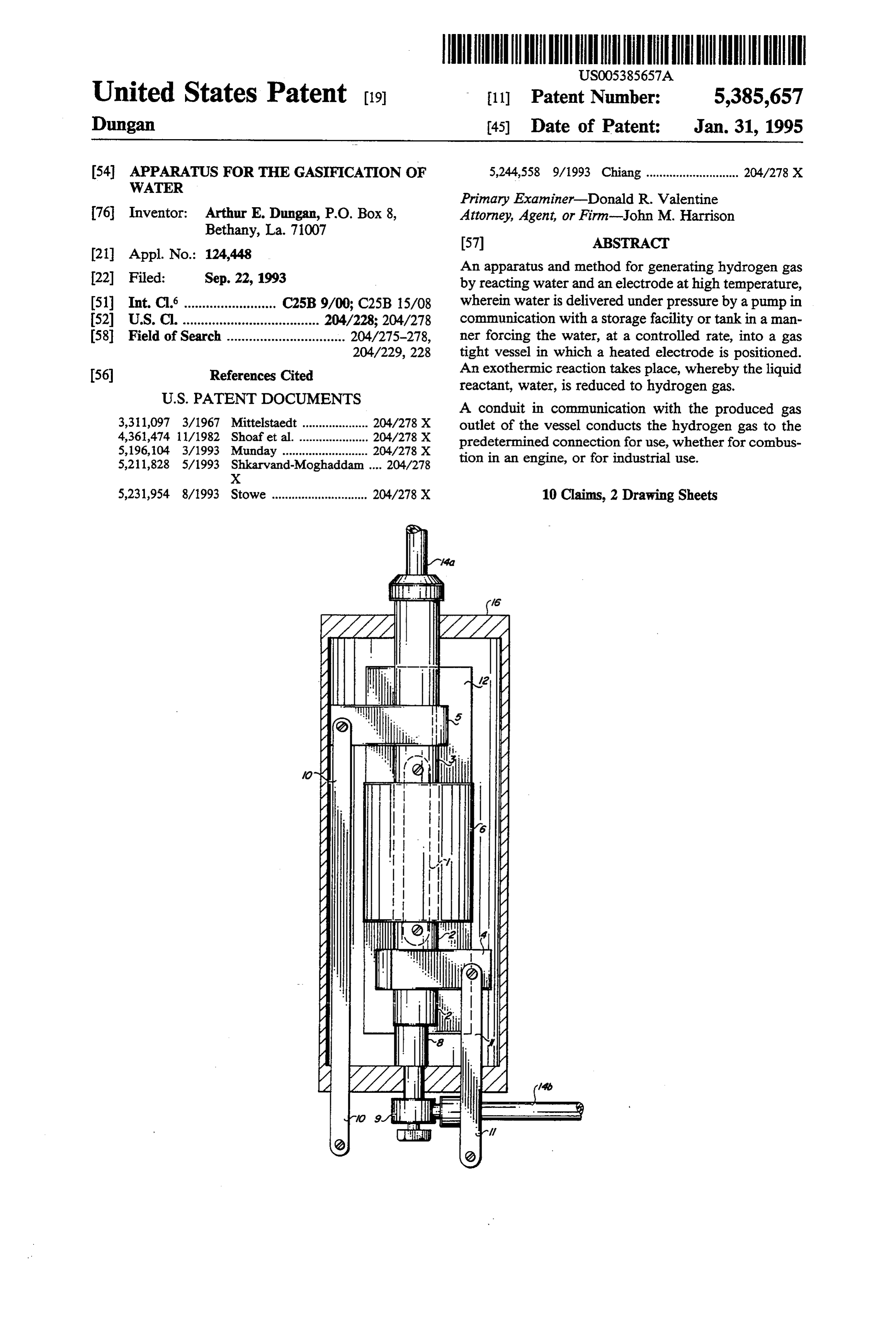
Page 2
Drawing sheet — no readable text.
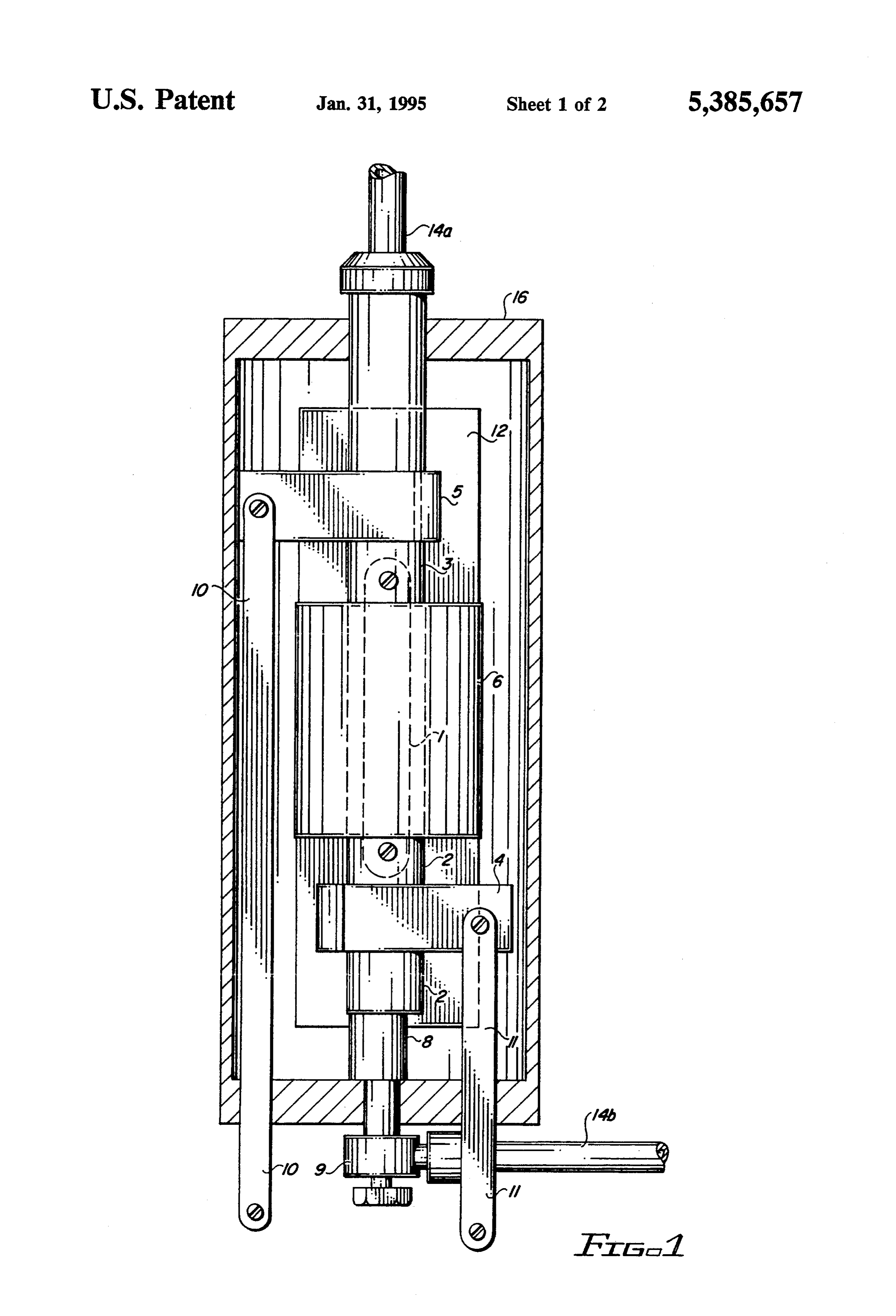
Page 3
Drawing sheet — no readable text.
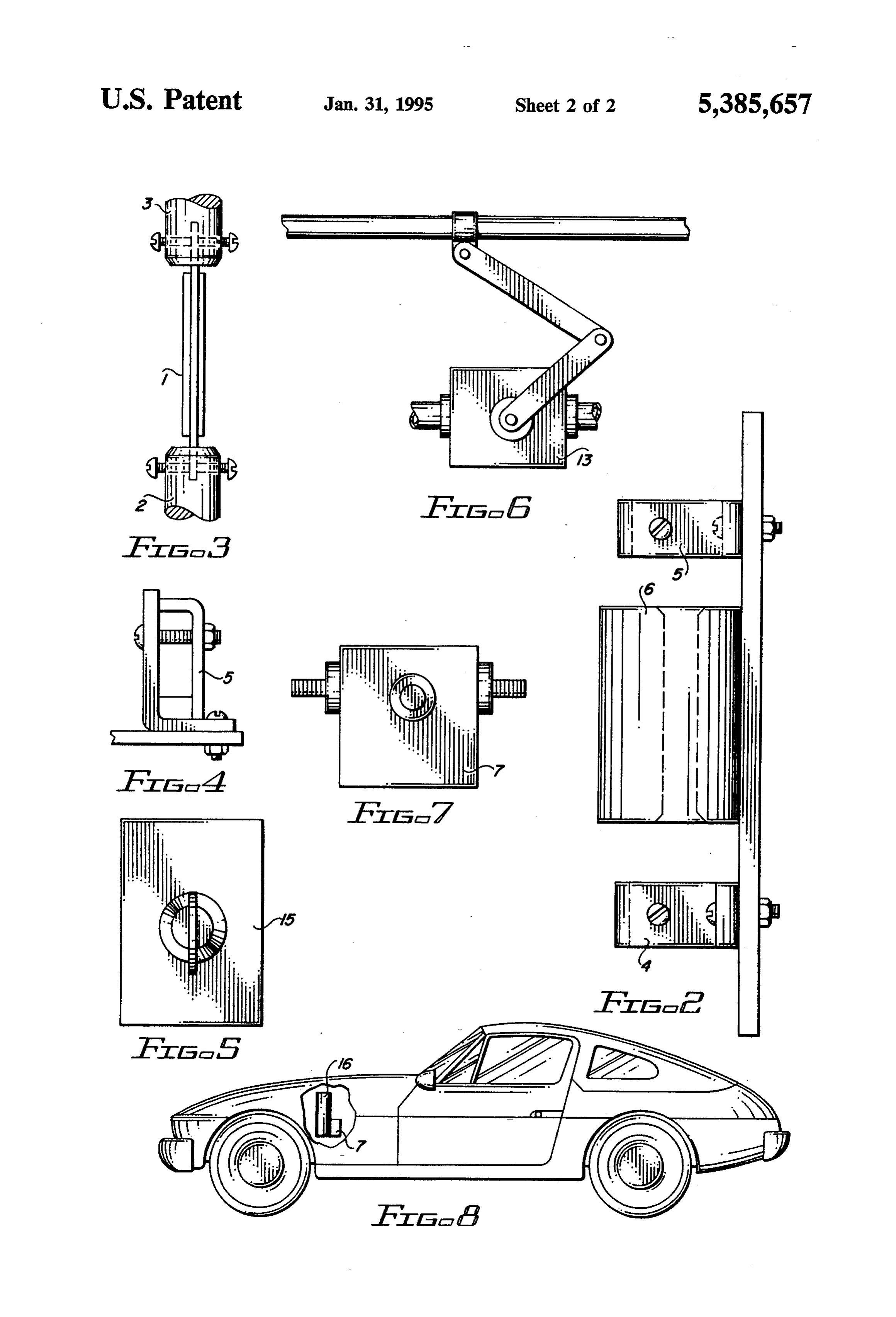
Page 4
APPARATUS FOR THE GASIFICATION OF
the vehicle, at neither cost nor danger to himself or herself, nor others.
WATER Hydrogen has been used on many projects as fuel in
FIELD OF THE INVENTION
research engines and proved superior to gasoline and diesel fuel, especially for quick starting in cold weather;
A chronology depicting the evolution of the gasifica as being in gas form, there is no delay for vaporization. tion of fuels would cover a period of time dating back to Engine wear was much less, and performance was sig the late nineteenth century, when gases were produced nificantly greater. An outstanding advantage was from pulverized coal. This method of producing fuel shown by the fact that the combustion of hydrocarbon became obsolete upon the introduction of the automo 10 produced no pollution, inasmuch as an innocuous water bile, which made manifest the necessity of supplying vapor was the only hi-product. The water vapor will gasoline in large quantities. prevent the formation of cyanogen (C2N2), which, to This demand was steadily increasing since that time, gether with hydrogen sulphide (H2S) is frequently pro reaching the point at which most of our gasoline is duced by catalytic converters from an over-rich fuel imported from foreign countries and has become a pro 15 mixture, and/or the presence of unburned hydrocar cess of transporting said gasoline thousands of miles, refining and distributing for use; this involves the con bons, subjected to the intense heat of the catalytic con verter. Both of these gases are among the most deadly tinuous handling of a combustible which is probably the of those known to man.
most unstable and unsafe of all known volatile fuels.
The reasons customarily stated regarding the fact
Therefore, it is the intent, by the revelation of the 20 that herein disclosed invention, to eliminate some, if not all, is thehydrogen has not been generally adopted as a fuel, problem of transportation and availability; this of the abovementioned hazards inherent in the use of hydrocarbons as fuel; the danger is ever present, as gas, in captivity, is considered to be more or less unsta these fuels can explode upon impact and cause serious ble; moreover, it is not easily obtainable in less popu lated areas. Also, reference is sometimes made to the injury, in addition to being one of the sources of massive 25 fiery polution of the environment. Said invention, being a blast of the dirigible Hindenburg in 1937. Hydro compact, individual generator for an automobile, can gen should be a simple solution to the problem of pollu assuage the demand for imported, flammable fuel and tion from the combustion of various fuels. compose a safety factor on the highways, while con Coal, for instance, has a history of creating poisonous serving the supply of petroleum and producing no polu 30 smoke, and even causing many deaths from the inhala tion. tion of colloidal particulates produced by the combus DESCRIPTION OF THE PRIOR ART tion of coal; as long ago as the thirteenth century in England, the use of some types of coal was banned.
The internal combustion engine has become suffi In the late 19th century in the United States, some of ciently commonplace in somewhat over one hundred 35 the hundreds of the hugh coke ovens such as the Coxe, years, to the extent that its dependability and generally Semet, Solvey, and Koppers, made coke and various efficient performance are not taken for granted. How biproducts such as gas, ammonia and methane, with ever, there is opportunity for improvement: those en little knowledge or concern for the protection of the gines on the market and in use today are totally depen environment, until the invention of the Cotrell Precipi dent upon a constant supply of fuel, the supply of which 40 tator. This process consists of electrically charging consists of one or another variety of hydrocarbon prod carbon and dust particles, then activating highly lictS.
For a brief period of time the early models of engines charged electrodes which attract the particles, neutral izing and depositing these particles as dust.
were operated using coal oil, methane and other fuels Gasoline and other hydrocarbons such as diesel fuel, extracted from lignite. Coal gas was made by distilling 45 methane, kerosene, coke and coal are probably the larg pulvarized coal and consisted mostly of methane, hy est producers of pollution at present. One poisonous gas drogen sulphide and carbon dioxide. Producer gas was produced by these fuels, carbon monoxide, (CO) have made from distilled coke and treated with steam. Water gas was also made from charcoal, coal or coke and been neutralized, to some extent, over the years by the treated with steam and oxygen. Hydrogen, the fuel 50 mandatory installation of the catalytic converter, to concerned with this invention, was made for industry gether with many environmental attachments. The con from methane by the cracking process, in which meth verter, while changing carbon monoxide into harmless ane was reduced to hydrogen; oxygen, also creates, under certain conditions, two more gases, equally as deadly; hydrogen sulphide 55 (H2S), which has the faculty of paralyzing the olfactory
CH-easte c + H2. nervous system, the only warning means of detecting its presence; and cyanogen (C2N2), which, if in contact
With the increase production of petroleum, gasoline with moisture, converts to hydrogen cyanide became the principle fuel for engines, and remains as (C2N2+H2O=HCN--HOCN). An over-rich fuel mix such today, regardless of being blamed as the cause of 60 ture produces unburned hydrogen particulates; and thousands of fire automobile crashes and subsequent upon contact with the intense heat of the catalytic con lawsuits. Also, as the production increases, the price of verter, produces these gases.
gasoline rises higher. For instance, a person who com The following U.S. patents are pertinent to the sub mutes one hundred miles per day, would probably feel ject of this application: U.S. Pat. No. 4,737,161, issued more at ease upon being able to fill his or her automo 65 Jan. 28, 1987, to D. F. Szydlowski; U.S. Pat. No. bile fuel tank from the garden hose, driving through the 4,950,460, issued Oct. 3, 1988, to John C. Goodwin; rush hour with the knowledge that the propellant for U.S. Pat. No. 4,702,894, dated Oct. 23, 1985, to Francis the automobile was being generated under the hood of Cornish.
Page 5
Publications pertinent to the subject of the applica tion are as follows: General Chemistry, 1976 edition pp. BRIEF DESCRIPTION OF THE DRAWINGS 168-179, 568-595 and 858-859. FIG. 1 is a side view, partially in section, of the pres American Fuels, 1922 edition, pp. 44-81, 185-191 and ent invention in completion, with all of the components 329-393. indicated by number;
Automotive Mechanics, 1975 edition, pp. 141-188. FIG. 2 is a side view of the heat-resistant supporting SUMMARY OF THE INVENTION base, with the reactor vessel, the negative terminal and the positive terminal mounted in place;
In an effort to relieve this situation, the present inven FIG. 3 is a side view of the electrode mounted in the tion as disclosed herein presents an apparatus enabling 10 two electrode holders;
the engine to be more self-sufficient, by having the FIG. 4 is a side view of the position terminal illus wherewithal for producing the fuel for its own use, trated in FIG. 3;
from ordinary water. By the engine being equipped FIG. 5 is a front view of the automotive type switch, with this device, instead of the currently used propel which activates the fuel pump therefor. lant which cost over $1.00 per gallon, fuel can be avail 15 FIG. 6 is a side view of the flow regulator valve, able free of charge. In addition, this fuel is pollution which controls the amount of second reactant in transit free, and the danger of fire is eliminated as the newly through the conduit to the metering nozzle; generated fuel is consumed instantly upon being pro FIG. 7 is a top view of the solenoid switch, which duced. closes the circuit energizing electrode, for the produc The apparatus herein presented thus generates an 20 tion of hydrogen;
efficient gas, to be used as a fuel; this is accomplished FIG. 8 is a side view of an automobile, showing the with only a minimal amount of pressure within the present invention installed under the hood thereof. system of the device. The pump supplying the liquid DESCRIPTION OF THE PREFERRED reactant creates a pressure perhaps two pounds; this pressure dissipates upon the egress of the water through 25 In reference to FIG. 1, an apparatus is shown depict the negative electrode holder. The reaction, when taken ing the herein described invention for the purpose of place in the reactor vessel, disposes less than one pound generating hydrogen gas from the reaction between the of pressure. The generated gas is drawn into the com first reactant, an electrode, and the second reactant, bustion chamber by the vacuum-creating action of each Water.
piston, in turn, upon the intake stroke of each cylinder. 30 FIG. 8 illustrates an automobile which is fueled by An apparatus and method for producing an efficient hydrogen generated by the apparatus.
propellant by means of effecting a chemical reaction Referring to FIGS. 1-7 the apparatus includes a gas wherein water is reacted with an electrode composed of tight reaction vessel, (6), an electrode, (1), two hollow certain elements, and energized by an electrical current, electrode holders, (2 and 3); a metering nozzle (8), two bringing the electrode to the proper temperature, at 35 electrical terminals, (4 and 5), a flow regulator valve which the reaction takes place, producing hydrogen gas (13), a solenoid switch (7), an automotive type switch to be used as fuel. (15), two conduits, (9 and 14), a mounting plate (12) and The electrode is secured in place by being operation a housing (16), together with the necessary connecting ally connected, at each end, to an electrode holder and cables (10 and 11). The water supply equipment such as having a gas tight reaction vessel between, and in juxta fuel tank and fuel pump are not shown. position with, the tips of the holders, with the electrode Shown in FIG. 1 is an electrode (1), positioned in an centered longitudinally inside the vessel. One of the aligned manner in said electrode holders (2 and 3) and holders is equipped to accommodate a metering nozzle, extending longitudinally through the reaction vessel (6), for the purpose of measuring the infusion of water into both ends of the vessel being counterbored to accomo the vessel and positioned upon the negative terminal of 45 date the bevelled tips of the electrode holders (2 and 3) the circuit, while the other holder is disposed for the these being in close juxtaposition with the vessel (6) in egress of produced gas by being placed in communica order to form a gas tight seal.
tion with a conduit which is operationally connected to One of the electrode holders (2) is in consolidation the fuel inlet of the engine, with the electrode holder with the negative terminal (4) and the threaded end of positioned upon the positive terminal of the electrical 50 the holder is joined with metering nozzle (8). Conduit circuit. (9) is joined to the threaded end, and the other end of The electrode, which is the first reactant, when at the the conduit is in Juncture with flow regulator valve proper temperature reacts to the increasing water, the (13). Access to the pump is provided by conduit (14) liquid reactant, and instantly reduces the water to hy being connected, at one end, to the flow regulator drogen, per equation: 55 valve, and at the other end, in communication with the fuel pump. Control of the flow regulator valve is ac complished by attachment and synchronization of the
catalyst
H. No. operating elements of the valve to the throttle linkage of the engine, in order to provide acceleration and deceler ation of engine speed. The fuel pump may be mounted
The result of the reaction is, the hydrogen drawn into near the bottom of the fuel tank or reservoir, or inside the engine and consumed as fuel, and the oxygen es the tank.
capes from the engine as a harmless vapor. The reason for the location of the metering nozzle, A reservoir or fuel tank may be used to maintain a and the consequent installation of the inlet for the sec constant supply of the liquid reactant, with a pump or 65 ond reactant, at the negative terminal, is this: An electri other means provided for its delivery into the apparatus. cal current characteristically flows from positive to The compact apparatus may be located under the hood negative; therefore, with the negative terminal being of an automobile, for the on board generation of fuel. energized first, the increasing water will arrive at the
Page 6
heated end of the electrode, and the reaction will take trode. The inside diameter of the reactor vessel should place one or two seconds earlier than it would were said be approximately one and one-half to two times the nozzle in communication with the positive terminal. To diameter or width of the electrode to be used; wall avoid confusion, two identical conduits are numbered thickness thereof should be about inch to one inch. (14). The ends of the inside diameter, or bore, should be Electrode (1) is connected at one end into the orifice counterbored to match the tapered ends of the electrode of electrode holder (2); reactor vessel (6) is positioned holders, in order to make the vessel gas tight. When to encompass the electrode (1), while the vessel (6) is modulated to satisfaction, vessel should be baked in a pressed into copulation with the tapered tip of electrode ceramic oven at a temperature of about 2100 F. holder (2). Electrode holder (3) is placed over electrode 10 Positive and negative cables leading from battery to (1), then is firmly pressed into junction with the coun solenoid should be of comparable size to A.W.G. 1, terbored end of reaction vessel (6), and screw or screws with a nominal O. D. of 0.530". Those leading from tightened in order to attach electrode (1) securely, thus solenoid to apparatus should be of equivalent diameter. completing a gas tight connection together with a firm Said diameters permit minimal resistance to the current, electrical attachment. The externally threaded end of 15 allowing reactant #1 to perform with greater effi electrode holder (3) is to be united with conduit (14) ciency. The current should be furnished by a storage and the gas product outlet thereof is placed in commu battery with a capacity of six to nine hundred cold nication with the fuel inlet, or damper container, of a cranking amperes. The electrical terminals may be fuel injection the engine, or the corresponding inlet made of flat copper bar stock, inch by 1 inch, two facility for engines equipped for stratified fuel, or the pieces four inches in length, two pieces three inches in older type engine equipped for carburetion. length, and all pieces drilled and bent as shown. The This apparatus may be easily made by any person terminals are to be mounted in correct position, upon with average skill and having access to a small lathe, a asbestos plate and protected by housing as shown. small drill press, a work bench with vise, a hack saw, The ignition switch of the automobile is turned to the ball pein hammer, tap handle, a -28 tap, a N.P.T. tap, 25 first, or ignition position, to energize the solenoid pliers and screw driver. switch (7), this heating the electrode (1). This position The electrode may be composed of metal, non-metal should be held for about five seconds, then the automo or chemical compound capable of reducing water to tive type switch (15) should be closed to activate the hydrogen, or other flammable gas at certain tempera fuel pump, to force water through the negative elec tures. A combination of stainless steel and magnesium, trode holder into reaction vessel, and into contact with in the form of rapidly heating thin strips, forms the most the heated electrode. Then the ignition should be efficient electrode, as neither of these active metals is moved to the starting position to begin operation of the subject to, or affected by, erosion or oxidation resulting engine. The sequence is as follows: from contact with water. The reducing power of mag 1. Turn ignition to first position, hold five seconds. nesium is well known, also an unlimited supply exists; 35 2. Energize secondary circuit by automotive switch. magnesium metal is produced by electrolysis from mag 3. Move ignition switch to start position. nesium chloride (MgCL2), which is available in inex I claim:
haustable quantity, as it is a major component of sea 1. An apparatus for generating hydrogen gas from water; one cubic mile of sea water contains approxi water using a source of electric power, said apparatus mately six million tone of magnesium chloride. Stainless comprising a hollow reaction vessel; a water intake steel conducts both heat and electrically more effi conduit positioned in fluid communication with one end ciently than does magnesium, the causing the reaction of said reaction vessel and a gas outlet conduit posi to occur more rapidly. tioned in fluid communication with the opposite end of The electrode holders may be made of round copper said reaction vessel; an electrode connected to the bar stock, by the use of the small lathe; one end of each 45 source of electric power and extending through said should be slightly bevelled, to match the corresponding reaction vessel and having a first end secured in said counterbored end of the reactor vessel. The holder to water intake conduit and a second end secured in said be mounted upon the negative terminal should be bored gas outlet conduit; pump means provided in fluid com : inch in diameter to a depth of 1 inches to receive the munication with said water intake conduit for pumping end of the electrode; then bore on through with a small 50 water into said water intake conduit; switch means drill, a 3/32 or a #40 drill: next, counterbore the other provided in electrical communication with said elec end of the electrode holder with a #6 drill to a depth of trode and the source of electric power for selectively ; inch and tap with a N.P.T tap, to accomodate the energizing said electrode, whereby said electrode is metering valve. The electrode holder to be mounted heated responsive to operation of said switch means and upon the position terminal should be bored through 55 electric power, and water is caused to flow through said with a inch drill, and the gas outlet end thereof should water intake conduit into said reaction vessel and be threaded to allow operational connection with the contacts said electrode and is converted into hydrogen conduit leading to the fuel intake facility of the engine. and oxygen gas for exiting said gas outlet, responsive to Each holder should then be drilled and tapped to re operation of said pump means.
ceive -28 screws close to the bevelled ends; one screw 2. The apparatus of claim 1 comprising a housing on each side of each holder, to serve as electrical enclosing said reaction vessel, said water intake conduit contact with the electrode end, and also to sectors said and said gas outlet conduit.
electrode in place. ' 3. The apparatus of claim 1 comprising a first elec Reactor vessel should be made of refractory brick trode holder in said water intake conduit and releasably mix, available on the market, or from the McMaster 65 engaging one end of said electrode, a metering nozzle Carr Co, in Chicago. Size is not critical, but need not be positioned in said water intake conduit in fluid commu over three and one-halfinches in length, and should be nication with said first electrode holder, a second elec at least one and one-half inches shorter then the elec trode holder in said gas outlet conduit and releasably
Page 7
engaging the opposite end of said electrode and an second electrode holder for transporting the hydrogen outlet pipe positioned in fluid communication with said and oxygen gas from said reaction vessel. second electrode holder for transporting the hydrogen 9. An apparatus for generating hydrogen gas from and oxygen gas from said reaction vessel. water and distributing the hydrogen gas to the engine of 4. The apparatus of claim 1 comprising a housing a vehicle having a battery, comprising a hollow reac enclosing said reaction vessel, said water intake conduit tion vessel; a first electrode holder positioned in fluid and said gas outlet conduit and releasably engaging one communication with one end of said reaction vessel and end of said electrode, a metering nozzle positioned in a metering nozzle positioned in fluid communication said water intake conduit in fluid communication with with said first electrode holder; a second electrode said first electrode holder, a second electrode holder in 10 holder positioned in fluid communication with the op said gas outlet conduit and releasably engaging the posite end of said reaction vessel and a gas outlet pipe opposite end of said electrode and an outlet pipe posi positioned in fluid communication with said second tioned in fluid communication with said second elec trode holder for transporting the hydrogen and oxygen electrode holder and the engine of the vehicle; an elec trode extending through said reaction vessel and having gas from said reaction vessel. 15 a first end secured in said first electrode holder and a 5. The apparatus of claim 1 wherein said switch second end secured in said second electrode holder; a means comprises a solenoid switch. mount plate secured to said first electrode holder, said 6. The apparatus of claim 5 comprising a housing reaction vessel and said second electrode holder for enclosing said reaction vessel, said water intake conduit mounting said apparatus on the vehicle; a negative con and said gas outlet conduit. 20 necting cable connected to said first electrode holder 7. The apparatus of claim 5 comprising a first elec and the vehicle and a positive connecting cable con trode holder in said water intake conduit and releasably nected to said second electrode holder and the battery; engaging one end of said electrode, a metering nozzle a solenoid switch connected to said positive connecting positioned in said water intake conduit in fluid commu cable for selectively energizing said electrode; and a nication with said first electrode holder, a second elec 25 pump connected to said metering nozzle for pumping trode holder in said gas outlet conduit and releasably water through said metering nozzle and into said reac engaging the opposite end of said electrode and an tion vessel, whereby said electrode is heated responsive outlet pipe positioned in fluid communication with said to manipulation of said solenoid switch and water is second electrode holder for transporting the hydrogen pumped through said metering nozzle and said first and oxygen gas from said reaction vessel. 30 electrode holder into said reaction vessel and contacts 8. The apparatus of claim 5, comprising a housing said electrode and is converted into hydrogen and oxy enclosing said reaction vessel, said water intake conduit gen gas and said hydrogen and oxygen gas is distributed and said gas outlet conduit and comprising a first elec through said second electrode holder and said gas outlet trode holder in said water intake conduit and releasably pipe and to the engine of the vehicle, responsive to engaging one end of said electrode, a metering nozzle 35 operation of said pump.
positioned in said water intake conduit in fluid commu 10. The apparatus of claim 9 comprising a housing nication with said first electrode holder, a second elec enclosing said metering nozzle, said first electrode trode holder in said gas outlet conduit and releasably holder, said reaction vessel, said second electrode engaging the opposite end of said electrode and an holder and said gas outlet pipe.
outlet pipe positioned in fluid communication with said 40 it is k
Provenance
- Collection
- Cited prior art
- Original PDF
- patentimages.storage.googleapis.com →
- Filed
- 1993-09-22
- Pages
- 7
- Method
- pdftotext (the PDF's own text layer) + pdftoppm 300dpi page scans
- Source
- Google Patents bibliographic record
- Granted
- 1995-01-31
- Inventors
- Arthur E. Dungan
- Transcribed from
- patentimages.storage.googleapis.com →