patent · US6113387A
Method and apparatus for controlling kiln
5 September 2000
Page 1 — bibliographic record
United States Patent (19) 11 Patent Number: 6,113,387 Wilson et al. (45) Date of Patent: Sep. 5, 2000
54 METHOD AND APPARATUS FOR 4,094,629 6/1978 Greenawalt. CONTROLLING KILN 4,097.225 6/1978 Rourke.
75 Inventors: Herb G. A. Wilson, Oakville, Canada; 4,210,632 7/1980 Rourke. efferW Thompson. Atlanta, Ga.; 4,315,735
Jeffery pSOn, Atlanta, Ja..., 4,372,784 2/1983 Hess.
Robert Perricone, New Tazewell; 4,465,455 8/1984 Meyer ....................................... 431/27 Michael Barkdoll, Knoxville, both of 4,747,773 5/1988 Predescu et al..
Tenn. 5,460,517 10/1995 Scheibenreif et al. .................... 432/95 5,486,107 1/1996 Bonne .................... ... 431/121 73 Assignee: Global Stone Corporation, Ontario, 5,816,792 10/1998 Spencer ... ... 431/90 Canad
Ca OTHER PUBLICATIONS
21 Appl. No.: 09/377,092 Fischbach et al., “Computer Control of a Coke-Fired Ver 22 Filed: Aug. 19, 1999 tical
LIme Kiln. Si
ReV, Fe
Related U.S. Application Data Primary Examiner Denise L. Ferensic
ASSistant Examiner Jiping Lu 63 Continuation of application No. 08/911,490, Aug. 14, 1997, Attorney, Agent, or Firm-Luedeka Neely & Graham PC abandoned.
7 57 ABSTRACT 51) Int. Cl.' ........................................................ F27D 1/08 52 U.S. Cl. .................. 432/99: 432/95; 432/96 A regenerative shaft kiln having at least two vertical shafts 58 Field of Search .................................. 432/36, 95, 96, and a plurality of lances for introducing fuel into the kiln, 432/97, 98, 99, 101, 102; 431/89, 90, 12, with one or more Sensor provided proximate a plurality of 75, 80, 78 the lances, each of the Sensors producing a first output Signal having a magnitude and corresponding to a physical param 56) References Cited eter of the kiln adjacent the sensor. Observation of the operating conditions of individual lances enables adjust
3,584.850 6/1971 Brandvold. ment damage and to improve kiln performance.
4,002,421 1/1977 Summer. 8 Claims, 13 Drawing Sheets
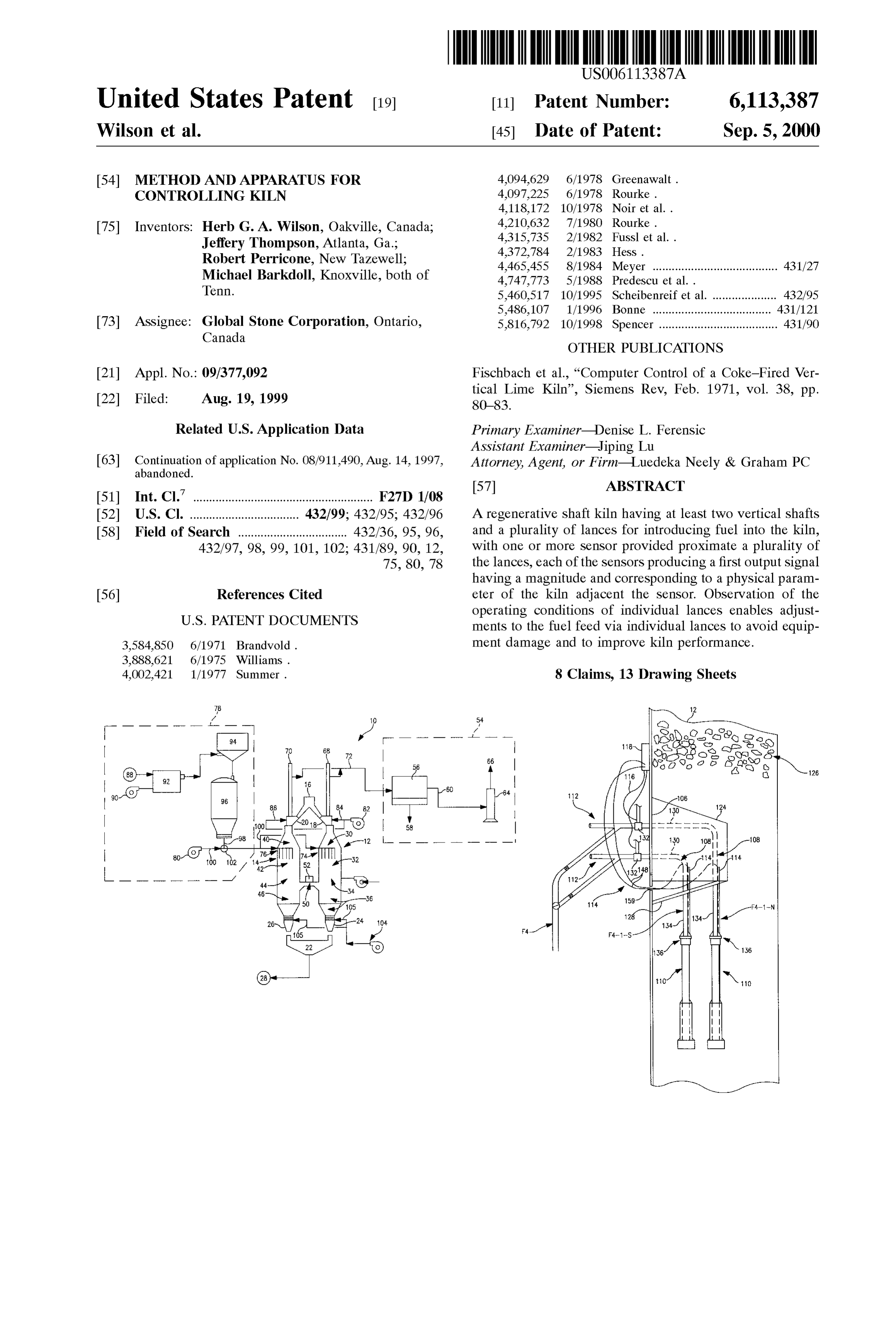
u --- -- ( - O 54 lie? assis - ------ -- (S) S-isses 70 t 72 18 3. aSS3 92 256 18 Özso 5 AESO A cy STN
E-98 { 08
Page 2
Drawing sheet — no readable text.
Page 3
Drawing sheet — no readable text.
Page 4
Drawing sheet — no readable text.
Page 5
Drawing sheet — no readable text.
Page 6
Drawing sheet — no readable text.
Page 7
Drawing sheet — no readable text.
Page 8
Drawing sheet — no readable text.
Page 9
Drawing sheet — no readable text.
Page 10
Drawing sheet — no readable text.
Page 11
Drawing sheet — no readable text.
Page 12
Drawing sheet — no readable text.
Page 13
Drawing sheet — no readable text.
Page 14
Drawing sheet — no readable text.
Page 15
METHOD AND APPARATUS FOR Another difficulty resides in control over the temperature CONTROLLING KILN within the kiln. For example, if the limestone is not sub jected to Sufficient temperature for Sufficient time, it will not
This application is a continuation of application Ser. No. be turned into lime. Also, if the temperature is too high 08/911,490 filed Aug. 14, 1997 abandoned. 5 (above about 1950 F) the limestone will over burn and have lesser value. Still another relates to the introduction of
FIELD OF THE INVENTION fuel into the kiln. For example, it has been experienced that This invention relates generally to kilns for firing aggre high cost lances used to introduce fuel into the kiln can be destroyed by overheating.
gate materials. More particularly, this invention relates to a An attempt to overcome problems in kiln operation, multiple vertical shaft regenerative kiln for calcining lime particularly
Stone and to a method for operating the kiln which enables perature at theduring Start-up, has been to monitor the tem cross-over, at the top of the kiln and along the improved control over the kiln. height of the kiln using thermocouples embedded in the BACKGROUND AND SUMMARY OF THE refractory material inside the kiln. This method has proved INVENTION 15 ineffective, as damage to components of the kiln, particu larly fuel lances has been observed even when the measure
Lime, or quicklime, is the oxide of calcium, CaO, and is ments are within the desired range.
commonly obtained by calcining limestone. Limestone is Accordingly it is an object of the present invention to calcined in two main types of kilns, vertical or shaft kilns, provide an improved multiple shaft or regenerative kiln and and horizontal, rotary kilns. a method for controlling Such a kiln which avoids many of Shaft kilns are of two main varieties, Single shaft and the disadvantages of conventional regenerative kilns. multiple shaft. In both, Solid particulate matter (limestone or An additional object of the invention is to provide a kiln other mineral aggregate) is loaded into the kiln shaft or of the character described and a method for operating Such shafts from the the top of the kiln and slowly travel down the a kiln which facilitates operation of the kiln and avoids many shaft. In a Single Shaft kiln, the flow of gas is counter-current 25 of the problems associated with the use of particular fuels. to the travel of limestone. In a multiple shaft or so-called “regenerative kiln a croSSOver duct is provided between ofAnother object of the present invention is to provide a kiln lower portions of the shafts and not all of the shafts are conditions adjacentdescribed the character fuel feed which enables monitoring of lances within the kiln.
active at the same time. Air travels downwardly through the A further object of the present invention is to provide a active shaft and crosses to the other shaft and flows upwardly therethrough for preheating of the aggregate prior response method for controlling conditions within the lime kiln in to activation of the shaft. to measured conditions within the kiln to avoid destruction of lances within the kiln.
For example, in a double shaft kiln, only one shaft is Yet another object of the present invention is to provide an active at a time. During the active phase fuel, Such as improved method for Starting up a regenerative kiln. powdered coal, is introduced into the shaft via lances and 35 Still another object of the present invention is to provide combustion gases are flowed downwardly through the shaft a kiln of the character described which is uncomplicated in in the same direction as the travel of aggregate. The com bustion gases pass through the croSSOver duct between the configuration and economical.
shafts and travel upwardly through the inactive shaft. After A Still further object is to provide a lance construction a period of time, the airflow is reversed and fuel is intro 40 which is advantageous as compared to conventional lances. duced into the other Shaft. Thus, as used herein, the termi Having regard to the foregoing and other objects, the nology “regenerative shaft kiln” shall be understood to refer present invention is directed to a regenerative shaft kiln. to kilns of the type having at least two vertical shafts, According to the invention, the kiln includes at least two wherein combustion air is flowed downwardly in shafts Vertical shafts. Each shaft of the kiln includes a pre-heating during their active phase, through a croSSOver between 45 Zone in communication with a Source of aggregate for active and inactive shafts and upwardly through inactive introducing aggregate into the kiln and a fuel introduction shafts. Zone below the pre-heating Zone. One challenge of regenerative or multiple shaft kilns is A plurality of lances are provided within the fuel intro the initial or Start-up phase of these kilns. Because these duction Zone in flow communication with a Source of fuel kilns are often configured to calcine Several hundred tons of 50 for introducing fuel into the kiln. A combustion Zone is limestone per day and calcining requires a temperature of provided below the fuel introduction Zone, and a cooling about 1750 F., it can often take several days to obtain Zone is below the combustion Zone. A croSSOver Zone operating conditions within the kiln. Once the kiln is prop between the combustion Zone and the cooling Zone connects erly Started it can typically run for long periods of time the shafts is in flow communication with the croSSOver Zone without significant adjustment. However, getting to that 55 of at least one other shaft.
point requires considerable adjustment and activity on the A Sensor is provided proximate each of a plurality of the part of the operator with considerable loSS in equipment lances, each of the Sensors producing a first output Signal from damage and loSS of quality product from down-time having a magnitude and corresponding to a physical param and waste from poor operating conditions. Difficulty in eter of the kiln adjacent the Sensor.
Starting the kiln is typically a function of the fuel type and 60 A significant aspect of the invention relates to the con grade, with the more expensive fuels being easier to work figuration and operation of lance Systems which introduce with. For example, kilns using eXclusively natural gas are fuel into the kiln via the kiln. This enables an operator to typically easier to start up, but gas is considerably more monitor the operating conditions of individual lances and to expensive than coal. Also, European coal which is typically control the introduction of fuel into individual ones of the lower in volatile content than most coals found in the United 65 latices in response to the operating conditions. States is typically less troublesome than U.S. coals, but For example, in a preferred embodiment, both the pres much more expensive. Sure within the lances and the temperature of the tip of each
Page 16
lance are monitored, with the operator instructed to watch the kiln is preferably provided by a twin shaft regenerative for undesirable preSSure and/or temperature increases which vertical kiln available under the trade name NS-70 CIM are indicative of undesirable plugging of the lance. In REVERSY from Cimprogetti, S.P.A. of Bergamo, Italy, response to the operator becoming aware of high preSSure having a capacity of about 300 metric tons per day. and/or temperature readings for a given lance, the operator The kiln 10 includes a pair of preferably identical parallel, may take action to prevent damage to the expensive lances. vertical steel shafts 12 and 14 lined with a refractory One response is to shut off the fuel to the indicated lancematerial, Such as alumina, magnesia or fireclay brickS. for the next active cycle (about 15 minutes) which action has Limestone or other mineral aggregate Such as chalk, marble been observed to alleviate the problem in many cases. Thus, all containing in exceSS of 90% calcium carbonate is charged the invention enables close observation over the operation into the top of each shaft 12 and 14 from a hopper 16 or other and operating environment of the individual lances and supply source by way of inlets 18 and 20, respectively, and enables the operator to take action and prevent equipment the limestone is calcined as it descends slowly to the bottom damage, which is expensive both in terms of equipment cost to each shaft where it is discharged into a collection hopper as well as in loSS of production resulting from downtime 22 via outlets 24 and 26 from which it may be collected and and/or poor quality from inadequate proceSS conditions. 15 transferred to a storage Silo as at 28, for example. In an alternative embodiment, a computer monitors the The limestone supply is preferably a minimum of 97% temperature and pressure measurements from each lance, calcium carbonate and has been processed to be clear and displays those measurements and automatically shuts off or free of all deterious matter Such as clay, dust and having a decreases fuel flow to the lance in response to temperature minimum dimension of about 1 inch and a maximum and pressure measurements that exceed predetermined cri dimension of about 6 inches, with a preferred dimension of teria. about 2 inches by about 4 inches. The hopper 16 preferably includes Suitable metering and distribution mechanisms for
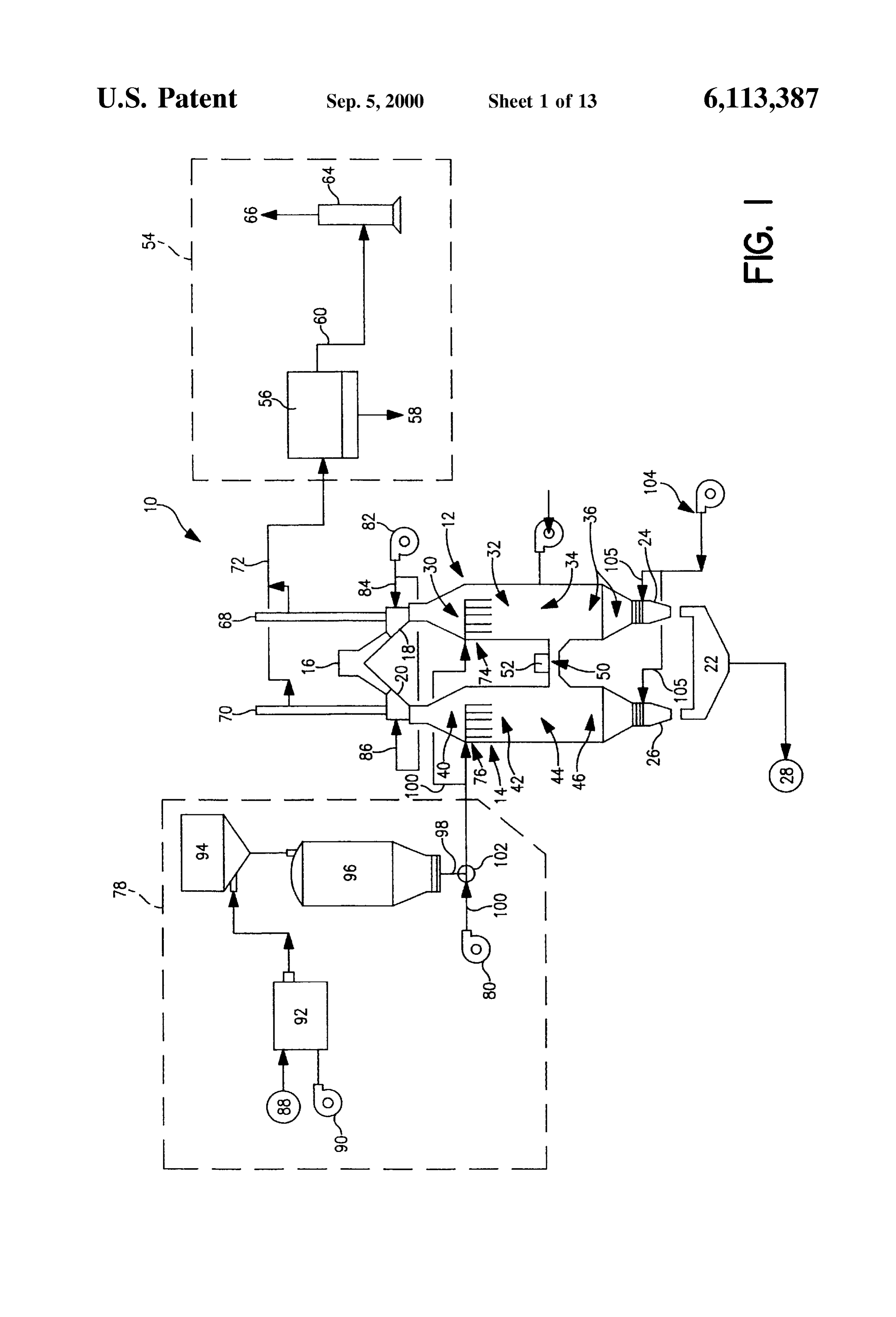
BRIEF DESCRIPTION OF THE DRAWINGS controlling the feed of material into the shafts 12 and 14. The above and other features and advantages of the 25 inlet The shaft 12 includes a preheating Zone 30 adjacent the present invention will become further known from the Zone 18, a fuel introduction Zone 32 below the preheating 30, a combustion Zone 34 below the Zone 32, and a following detailed description when considered in conjunc cooling Zone 36 below the combustion Zone 34 and in flow tion with the accompanying drawings in which: communication with the outlet 24. The shaft 14 likewise FIG. 1 is a schematic view of a kiln in accordance with the invention.
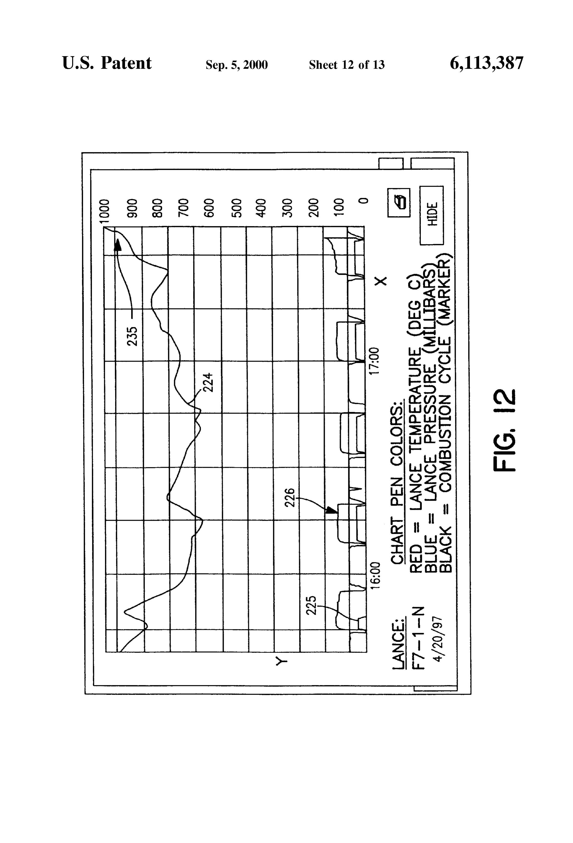
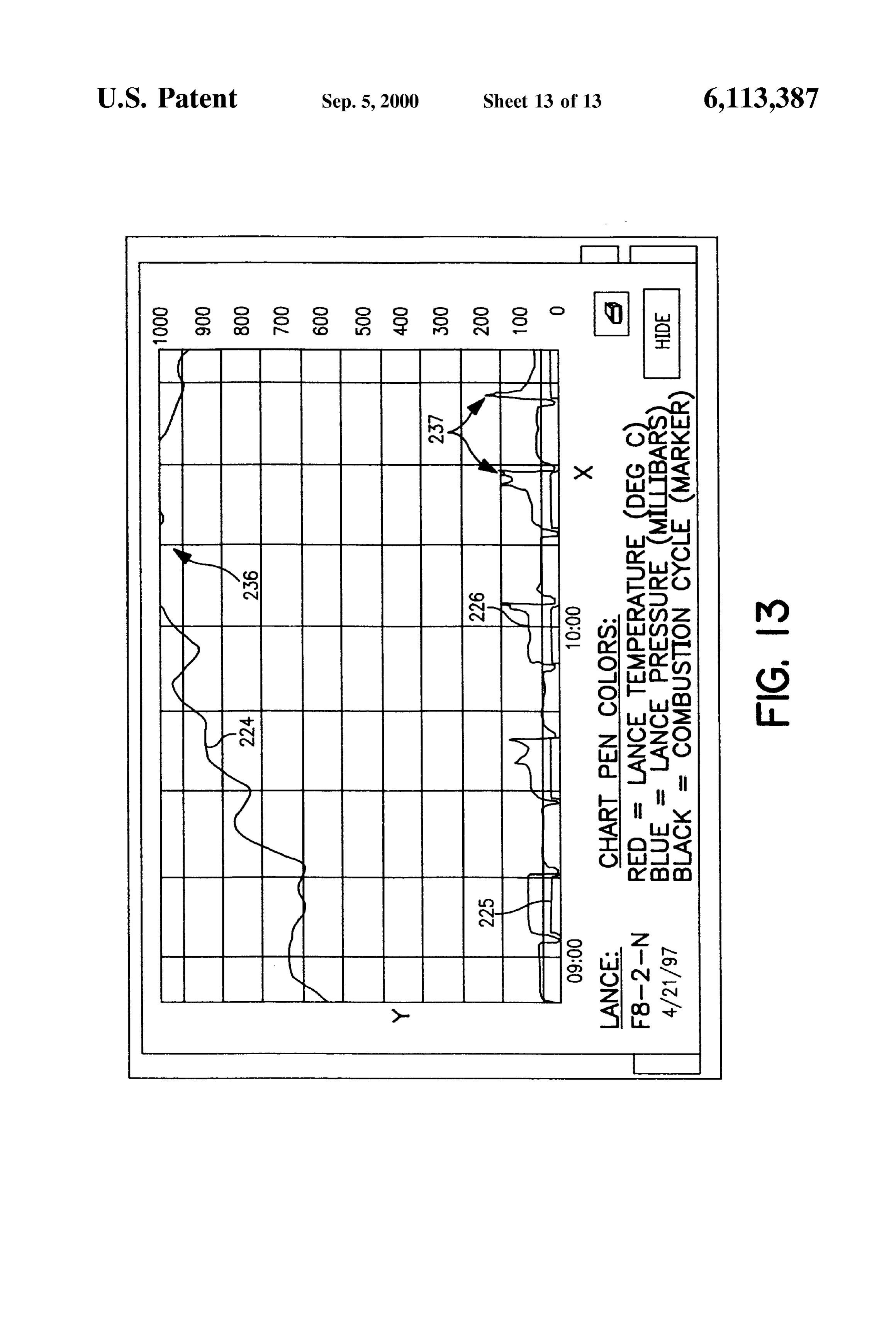
includes a preheating Zone 40, fuel introduction Zone 42, combustion Zone 44, and cooling Zone 46. An arched
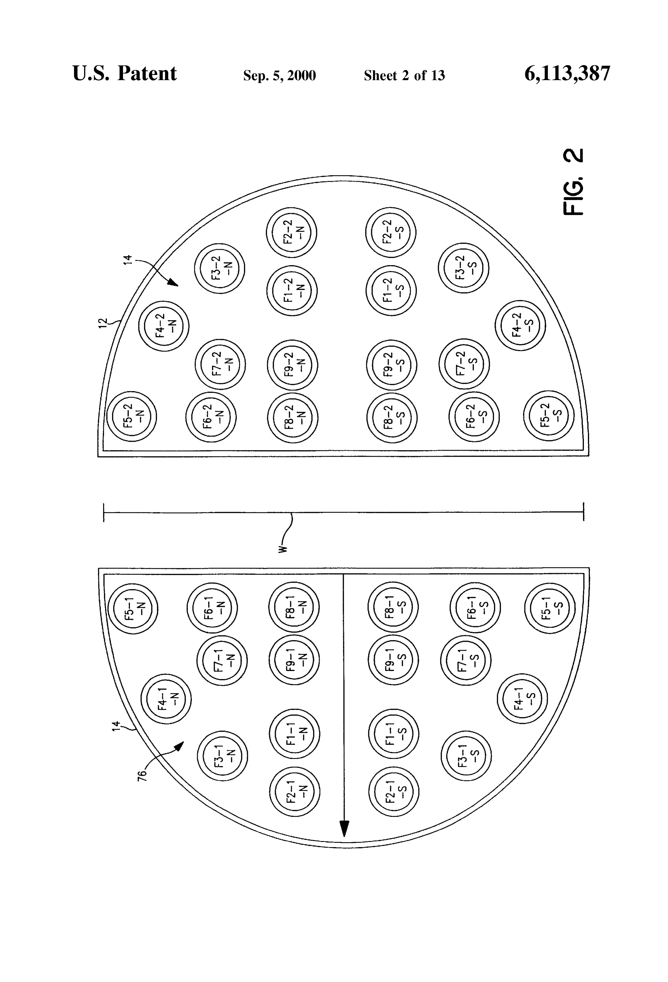
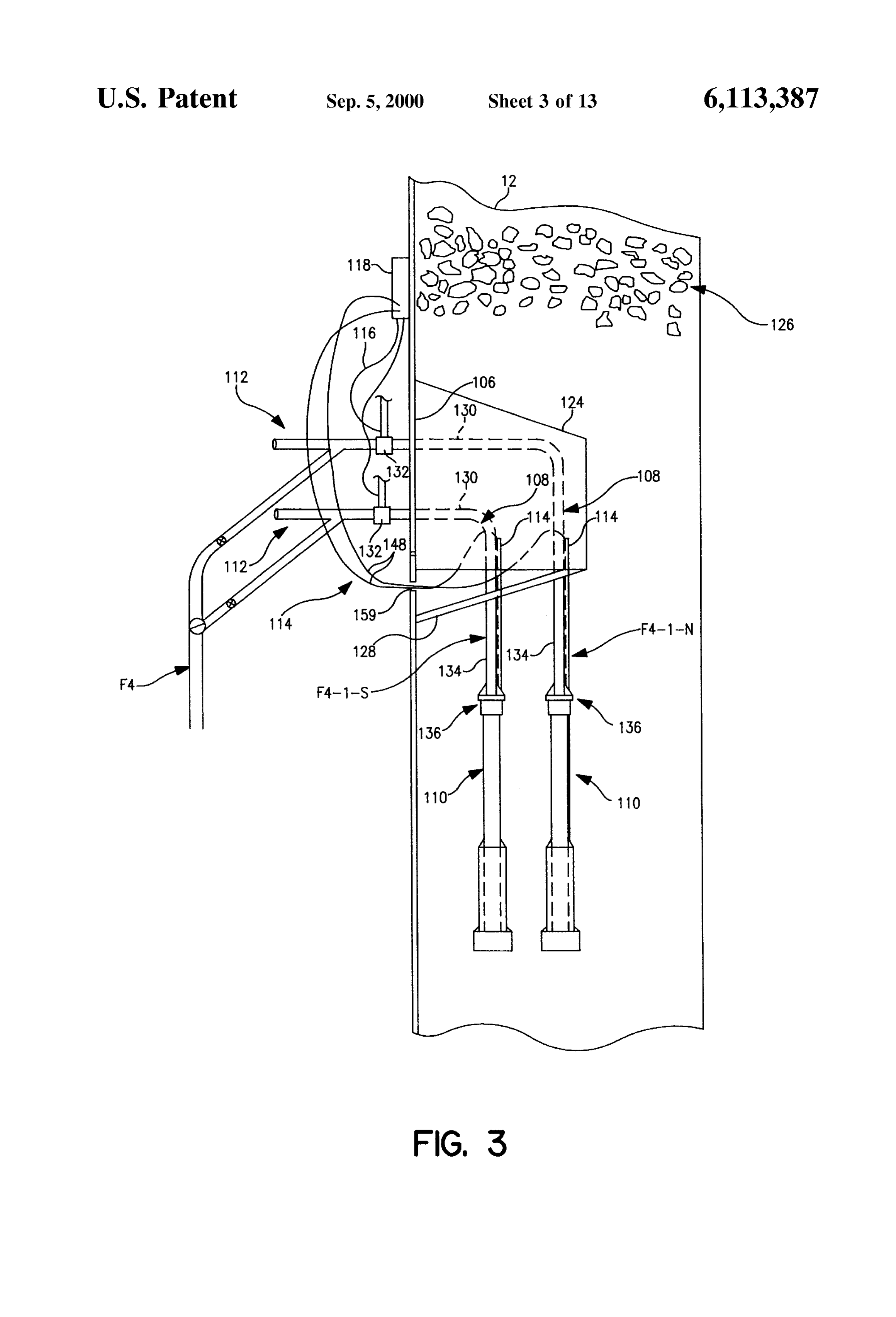
FIG. 2 is a top representational view of the D-shaped crossover duct 50 located between the combustion and shafts of the kiln and the arrangements of lances in the kiln cooling Zones connects the shafts 12 and 14. A Source of for delivering fuel. heat, Such as an oil injection lance 52, is preferably provided FIG. 3 is a side elevational view showing a pair of lances 35 within the crossover duct 50 for heating of the kiln during within the kiln. the Start-up phase.
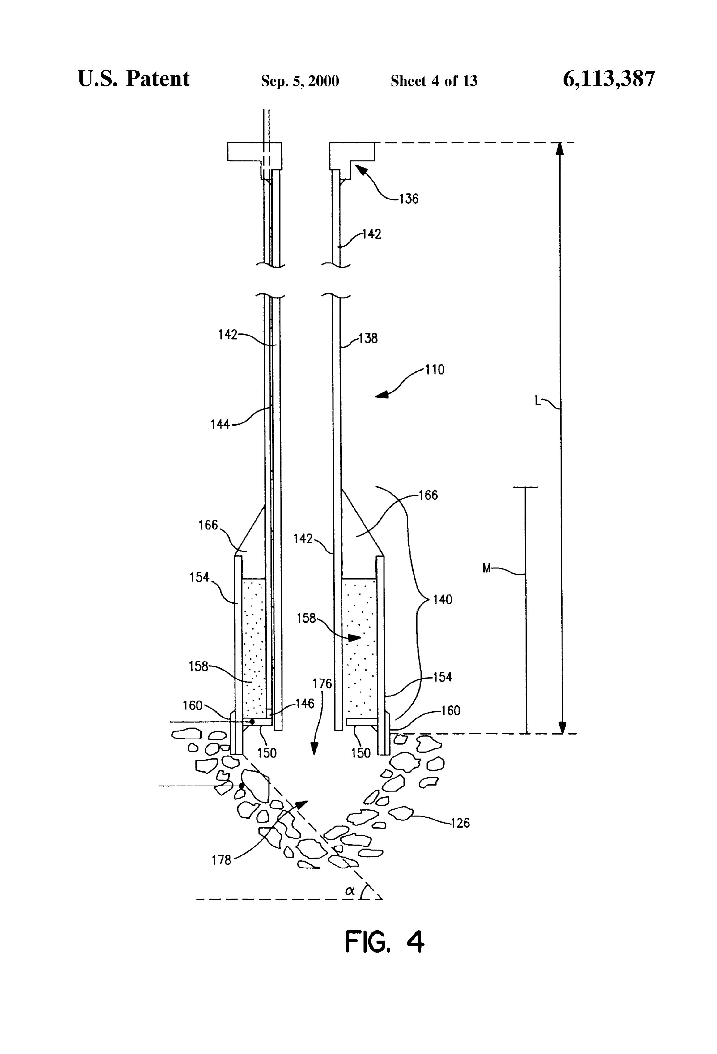
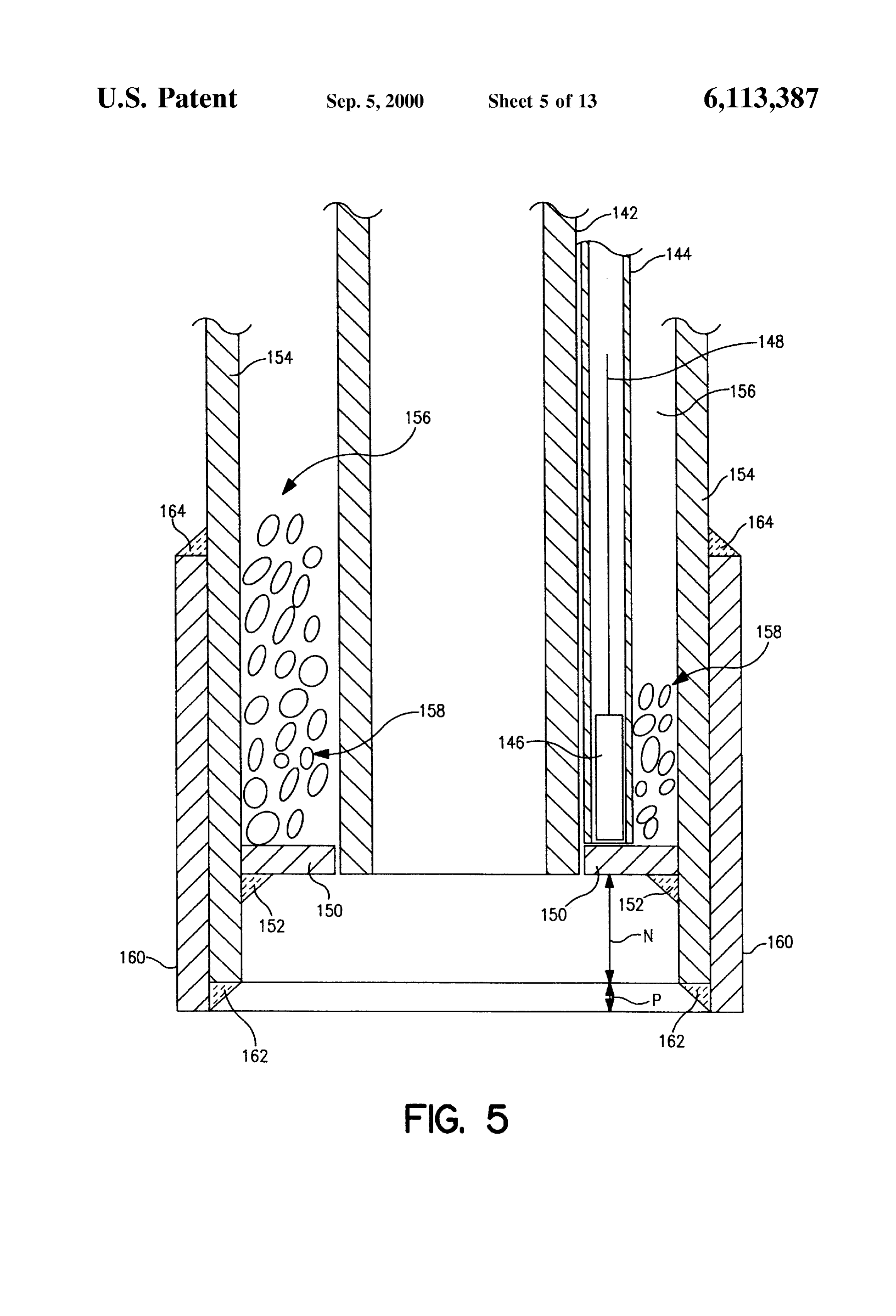
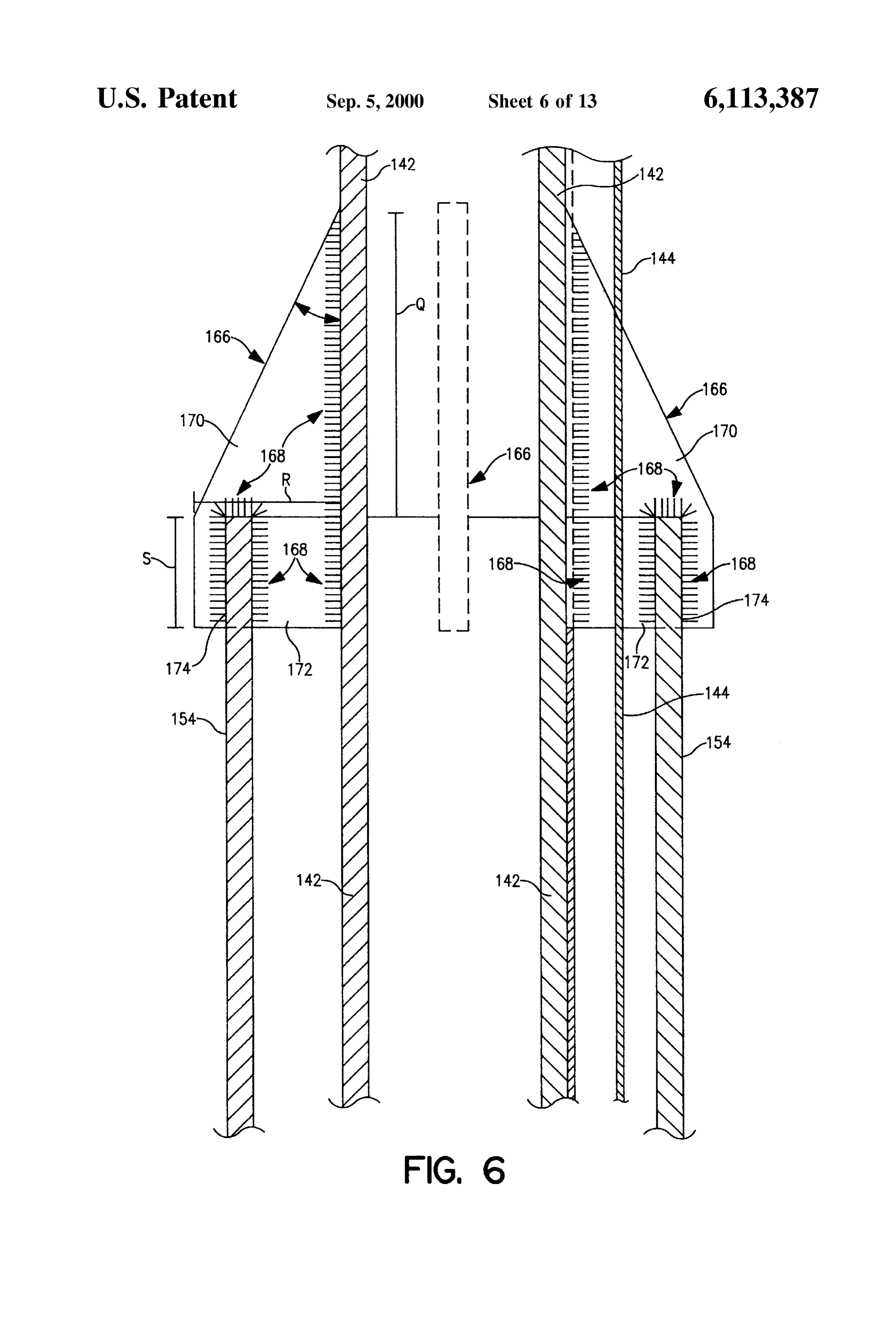
FIG. 4 is a lance having upper and lower Sections and For the purpose of an example, the shafts of the NS-70 provided with a Sensor in accordance with the invention. CIM-REVERSY kiln have an overall height of about 80 feet, FIG. 5 is a close-up cross-sectional view of a lower with the preheating Zone having a height of about 21 feet, the portion of the lower section of the lance of FIG. 4. 40 fuel introduction Zone a height of about 3 feet, the combus FIG. 6 is a close-up cross-sectional view of an upper tion Zone a height of about 13 feet, and the cooling Zone a height of about 17 feet. The width W of the d-shaped shafts portion of the lower section of the lance of FIG. 4. within the refractory lining is also preferably about 13.8 feet FIG. 7 is an enlarged detail view of a lance feed assembly across, with an inner radius R of about 6.9 feet (FIG.2). in accordance with the invention.
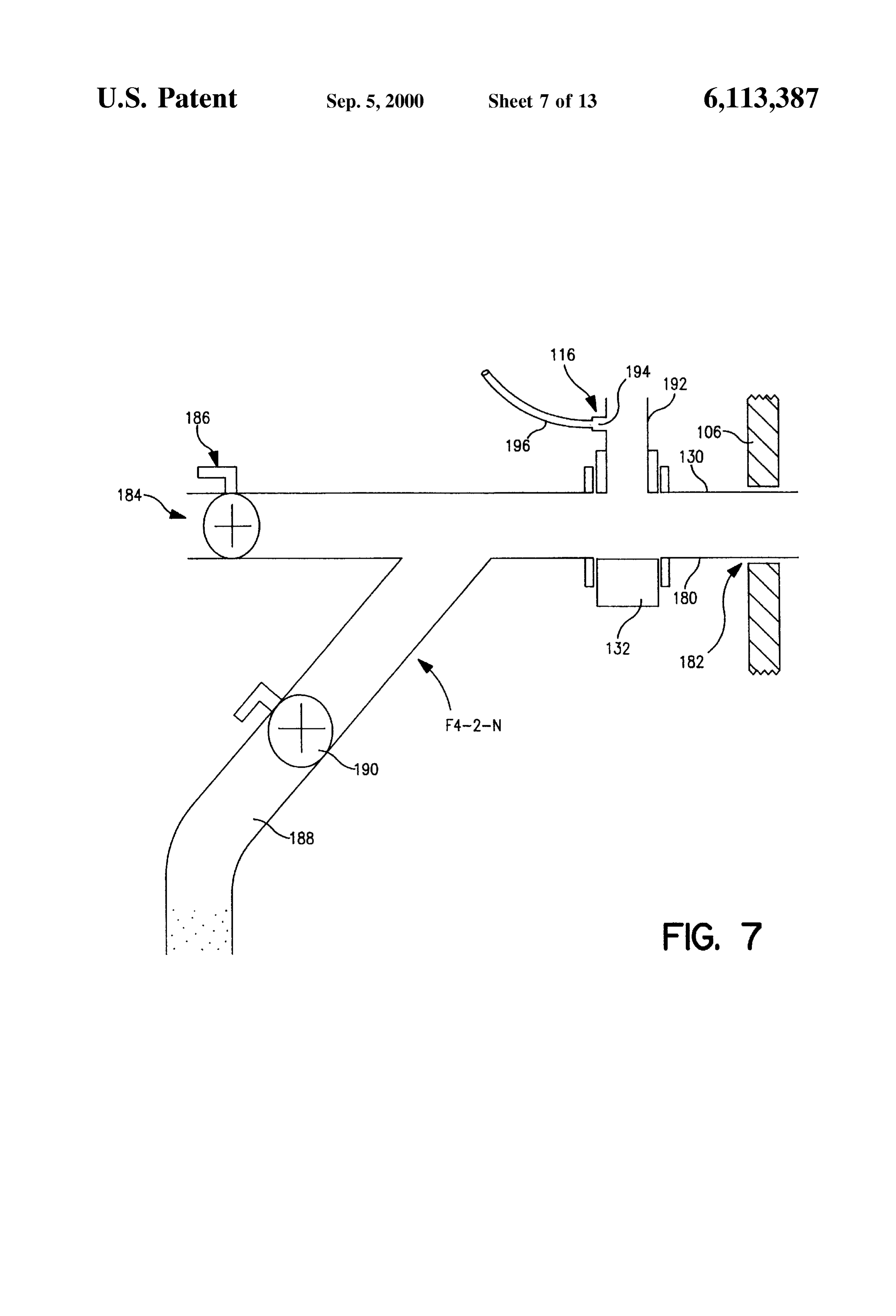
During operation of the kiln 10, only one shaft is active
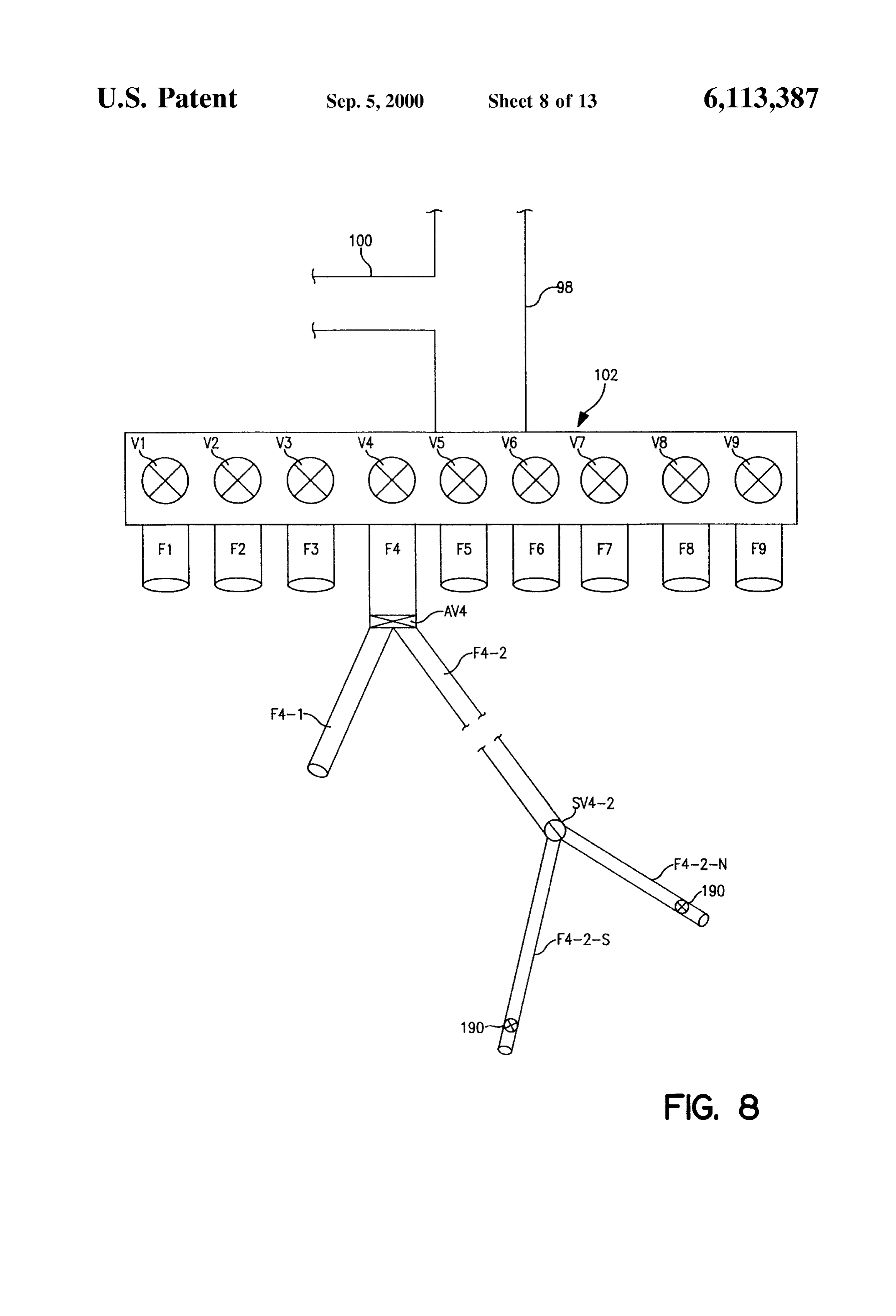
FIG. 8 is a schematic diagram of a fuel delivery system 45 at a time. The crossover duct 50 enables combustion gases Suitable for use in the invention. generated in the active shaft to enter the other “inactive” FIG. 9 is a detailed view of a pressure/temperature signal shaft for upward passage through the limestone in the processing System in accordance with the invention. inactive shaft before exiting to a pollution control system 54 FIG. 10 is a computer Screen display provided in accor 50 for treatment of kiln combustion gases and includes a dance with the invention for controlling the Supply of fuel to baghouse 56 from which solids (i.e., lime dust, etc.) may be lances. discharged as at 58 and gases discharged as at 60. The gases FIG. 11 is a computer Screen display showing lance are vented via stack 64 to the atmosphere as at 66. temperature and pressure versus time as monitored in accor The kiln configuration provides an airflow that is advan dance with the invention showing lance readings within the 55 tageous to preheat the material in the inactive shaft prior to desired range. activation of that shaft and thus allows recuperation of heat FIG. 12 is another computer display as in FIG. 11 but with and reduces fuel requirements. Outlets 68 and 70 associated showing a lance having temperature above the desired range. the shafts 12 and 14, respectively, are preferably routed FIG. 13 is another computer display as in FIG. 11 but 60 the Shafts 12 header to a common
72 for collection of exhaust gases from and transportion of the gases to the showing a lance having temperature and pressure above the pollution control system 54.
desired range. Lance systems 74 and 76 discussed in more detail below, DETAILED DESCRIPTION are provided within the fuel introduction zones 32 and 42 of the shafts 12 and 14, respectively, for injecting fuel from a
With initial reference to FIG. 1, there is shown a sche 65 fuel supply system 78 into the shafts during operation of the matic diagram of a regenerative kiln System 10 provided in kiln. The fuel is preferably injected by air preSSure in part accordance with the invention. The conventional portion of supplied by a blower system 80. The air from the blower
Page 17
S 6 system 80 also enters the shafts via the lance systems 74 and tems and to control of the introduction of fuel into individual 76 as explained below in connection with FIG. 8 and serves ones of the lances in response to the monitored conditions. as a Secondary Source of air for combustion. ExceSS air is THE LANCE SYSTEMS preferably introduced into the top of the shafts 12 and 14 via blower 82 and conduits 84 and 86 during injection to the fuel In a preferred embodiment, between about 16 and 20 to provide the primary Source of air for combustion. lances, preferably about 18 lances are provided as part of The fuel is preferably pulverized coal or coke or a mixture each lance system 74 and 76 within each shaft 12 and 14 and of the two, Such as high volatile bituminous coal found positioned to substantially evenly distribute fuel by pulsed typically in the U.S. states of Tennessee, Kentucky, West injection into the aggregate traveling down the Shafts. The Virginia, Pennsylvania, Wyoming, Colorado or petroleum lances are preferably positioned in an array Such as is shown coke produced as a byproduct of petroleum refining. in FIG. 2, with the Spacing between adjacent ones of the However, a variety of other fuels may be used, Such as lances preferably being from about 15 to about 24 inches natural gas, and heavy fuel oils. The fuel Supply system 78 apart, most preferably about 18 inches for the described preferably includes a source of the fuel 88, air blower 90, shafts.
mill 92 for pulverizing the fuel to a desired size, air classifier 15 AS will be seen, the lances are configured to enable 94 and fuel storage bin 96. Conduit system 98 from the bin monitoring of the temperatures at the tips of the lances and 96 and conduit system 100 from the blower 82 are in flow the pressure within each lance, it having been discovered communication with one another, the lance Systems 74 and that close observance of these parameters and appropriate 76 and a lance feed control system 102 for supplying and action in response to the observance of undesirable tem controlling fuel to the kiln, as will be described in more perature and or pressure can enable an operator to avoid detail below in connection with FIG. 8. damage to the lances as well as lost time and product It will be understood that the operation of the kiln begins asSociated with equipment damage. In addition, it will be with an initial start-up phase (Phase I) wherein aggregate is understood that various other lance parameters may also be loaded into the kiln. The Start-up phase typically lasts from 25 monitored to enable further improvements to the operation about 24 to about 36 hours or more. Heat for the initial of the kiln. For example, the makeup of the gases adjacent start-up is preferably provided by the oil injection lance 52. the lance tip or other regions of the kiln as well as other The Start-up phase ends when the Stone bed temperature is parameters may be monitored and reacted to in order to Sufficient to provide ignition of the fuel injected via lances provide improvements in kiln operation and product quality. 74 and 76 and it is then preferred to remove the burner 52 For ease of identification of the lances in connection with from the kiln. the computer monitoring System described Subsequent Production of lime begins with Phase I of the firing cycle. hereto in connection with FIGS. 10-13, the lances in each The exhaust gas ducting (68 or 70) above the active shaft is shaft are preferably identified by a three-phase number such shut off during Phase I and fuel and combustion air are fed as F1-1-N, wherein F1 stands for fuel line 1, the next number into the active shaft and the combustion gases generated in 35 (1) stands for shaft number (1 or 2) and the letter N stands the active shaft flow through the crossover shaft 50 into the for the North side of the shaft. However, it will be appre inactive shaft and exhausted to the pollution control System. ciated that other identification Schemes may be used. Lime is discharged from the bottom of the active shaft into AS can be seen from the numbering Scheme of the lances hopper 22 and cooling air is simultaneously injected into the depicted in FIG. 2, the kiln system preferably includes nine cooling Zone of each shaft via blower system 104 and 40 fuel lines, with each fuel line feeding two lances in each associated conduits 105 to coot the product lime from a shaft. Thus, in a preferred embodiment the fuel lances in temperature of about 1650 F. to about 150°F, preferably shaft 12 are numbered F-1-N, F1-1-S, F2-1-N, F2-1-S, about 180° F. F3-1-N, F3-1-S, F4-1-N, F4-1-S, F5-1-S, F5-1-N, F6-1-S, After Phase I are Phases II, III and IV, in seriatim. F6-1-N, F7-1-S, F8-1-N, F8-1-S, F9-1-N, F9-1-S and the Introduction of limestone into the Shafts occurs only in 45 fuel lances in shaft 14 are numbered F1-2-N, F1-2-S, Phases II and IV; however lime discharge from the shafts is F2-2-N, F2-2-S, F3-2-N, F3-2-S, F4-2-N, F4-2-S, F5-2-S, conducted only during Phases I and II. Phase I (and III) F5-2-N, F6-2-S, F6-2-N, F7-2-S, F8-2-N, F8-2-S, F9-2-N, typically have a duration of from about 10 minutes to about F9-2-S.
20 minutes, preferably from about 12 minutes to about 15 With reference now to FIG. 3, there is shown a pair of the minutes. lances (F4-1-S and F4-1-N) fed by a fuel line F4 and
In Phase II, fuel feed to all kiln lances is ceased and positioned within the shaft 12 for Supplying fuel into the combustion air, and cooling air is vented to the atmosphere kiln. As will be understood, fuel line F4 also feeds lances and limestone is fed into the previously active shaft. Phase F4-2-S and F4-2-N in the other shaft. The routing of the fuel II typically has a duration of from about 1 minute to about lines F1-F9 is described with more particularly below in 2 minutes. 55 connection with FIG. 8.
Phase III is identical to Phase I, however, the operations To facilitate installation of the lances and Subsequent of shafts are reversed from Phase I, that is, the active shaft access to the lances for maintenance and the like, an access becomes the inactive Shaft and Vice-versa. door 106 is preferably provided in the wall of the shaft 12. Phase IV is identical to Phase II, except limestone is Each lance is Substantially identical and includes an upper charged into the opposite Shaft charged in Phase II. 60 section 108, a lower section 110 and a lance feed assembly Lime discharged from the kiln may be transferred to a 112 (FIGS. 4–7).
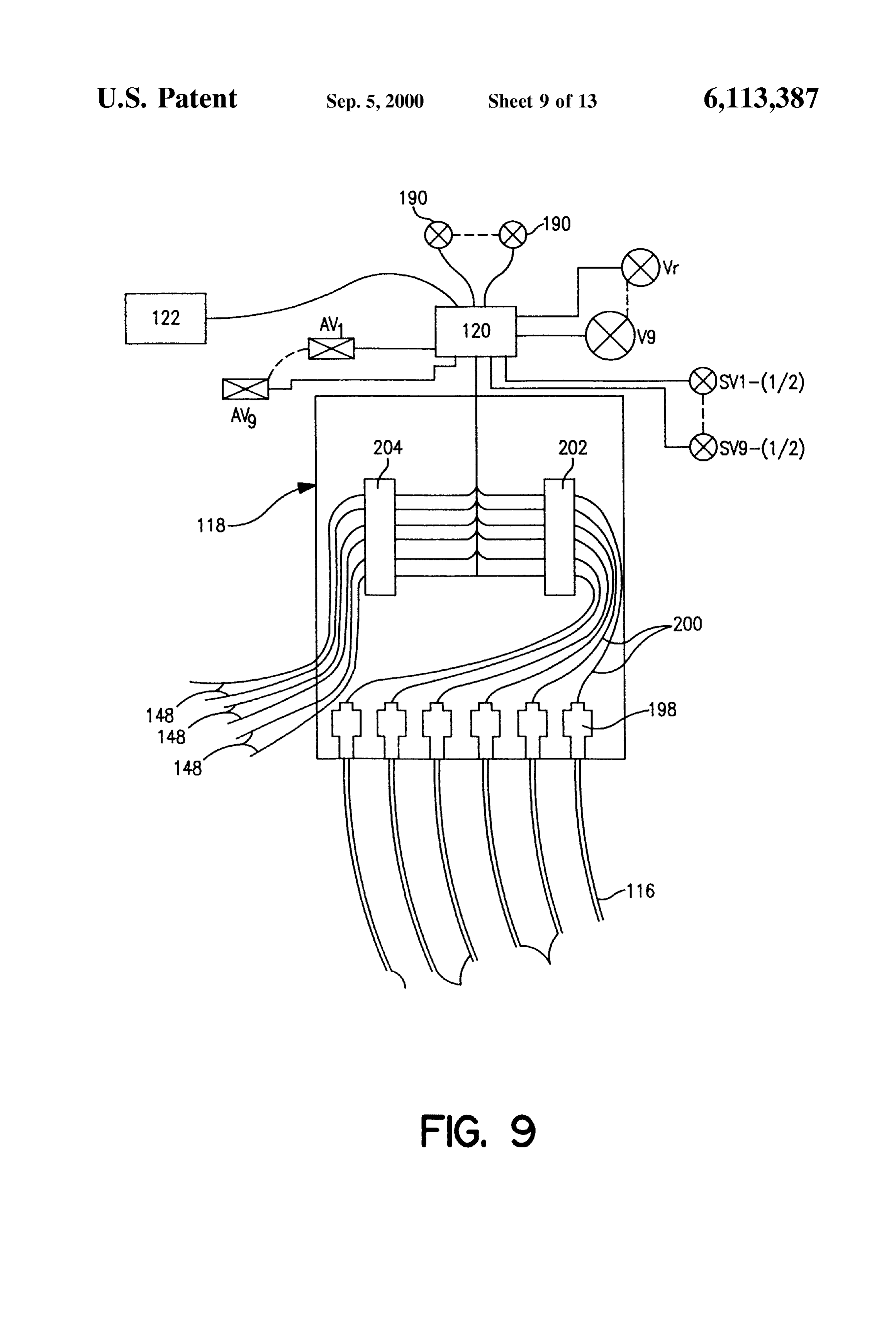
Screening and crushing System and thereafter to Storage Each lance is likewise preferably equipped with a tem and/or further processing. perature Sensor assembly 114 and a pressure Sensor assem AS will be explained in more detail, a significant aspect of bly 116 (FIG. 7) which are routed via a connector assembly the invention relates to the configuration and operation of 65 118, the output signals of which are routed to a process logic the lance systems 74 and 76, to the monitoring of certain controller 120 operatively associated with a computer con operating conditions of individual lances of the lance SyS trol system 122 (FIG. 9).
Page 18
An awning-shaped shield or deflector 124 is preferably for further rigidity. Preferably about four of the gussets are provided above the lances to Shield the lances from damage evenly Spaced apart from one another. Each guSSet 166 is from the limestone 126 traveling down the shaft. The shield preferably of one piece and includes an upper triangular is preferably made of heavy gauge, carbon Steel mounted as region 170 having a height Q of about 2 and % inches and by bolting or welding to the interior of the shaft and having a base R of about 1 and % inches, and a lower rectangular supports 128 for additional strength. region 172 having a height S of about 1 inch and including The upper section 108 connects the lance feed assembly a slit 174 defined thereon to receive the upper end of the pipe 112 to the lower section 110 for flow communication of air 154. A suitable material for the gussets is 4 inch thick 310 and fuel therethrough and is preferably provided by a length S.S. plate material sized to the above dimensions. of conduit to provide a horizontal section 130 which is The jacket pipes 154 and 160 serve to increase the connected by coupling 132 to the lance feed assembly 112, and a vertical section 134 which is connected by flange 136 diameter of the lower end of the lance and thus provides an to the lower section 110. The upper section 108 is preferably enlarged Zone 176 into which the fuel may expand as it provided by a length schedule 80 carbon steel conduit. leaves the lower end of the lance tubing 142. Without the With reference to FIGS. 4-6, the lower section 10 pref 15 jacket pipes, the ratio of the outer diameter of the lance to erably has a length L of from about 5 to about 15 feet, most the inner diameter of the lance is merely the ratio of the outer preferably about 10 feet, with upper portion 138 thereof diameter of the tubing 142 (e.g. 2.22 inches) to its inner having a length of about 7 feet and lower portion 140 having diameter (e.g. 1.72 inches), that is about 1.3. The thickness a length M of about 3 feet. The lower section 10 is preferably of the jacket pipes is Selected to increase the ratio of the provided by a 10 foot length of stainless steel tubing 142 outer diameter to the inner diameter to from at least about 2 having an outer diameter of about 2.22 inches, an inner to about 3, and preferably about 2.6, to provide structure to diameter of about 1.72 inches and referred to generally in the deflect the mineral aggregate away from the lower end of the trade as “HL' S.S. tubing. lance without changing the lance flow volume. In this With reference to FIG. 5, the lower portion 140 includes regard, it has been discovered that the construction of the a small-bore tube 144 attached to the tubing 142, preferably 25 lower end of the lance in accordance with the invention also by welding as by applying a 2 inch weld every foot, for Serves to prevent aggregate material (i.e., the limestone) receiving a temperature Sensor 146 and associated leads or from migrating into the area below the lance and thus wiring 148. The tube 144 is preferably stainless steel tubing provides a void space 178 below the lance which enables having an inner diameter of about ys inch, an outer diameter fuel and air from the lance to diffuse more readily into the stone 126 before it ignites. For the described lance, it has of about 5/8 inch and an overall length of about 13 feet such been that the tube 144 extends above the bend provided in the has anobserved angle of that the limestone below the lance typically repose C. of about 42.
upper section 108 of the lance and is protected from the migrating limestone by the awning 124 (FIG.3). The bottom FIG. 7 is a detailed view of one of the lance feed end of the tube 144 terminates against a Steel closing plate assemblies 112 for introducing air and fuel into the lances 150 provided adjacent the bottom end of the tube 142 and 35 and for obtaining pressure readings within the lance System. secured as by weld 152 to the bottom of a jacketing pipe 154 AS can be seen, the assembly 112 includes a main conduit which surrounds the lower portion of the tubing 142 to 180, one end of which is joined with section 130 of the lance provide an annular area 156 which is preferably filled with via coupling 132 for injecting air and fuel into the kiln. a suitable refractory material 158, such as a low thermal Section 132 exits the kiln through opening 182 in the door conductivity, castable refractory. 40 106. Open end 184 of the conduit 180 is selectively acces
The thermocouple 146 is preferably a standard “K” type sible via valve assembly 186 for insertion of cleaning thermocouple Suitable for use in the temperature range of devices and the like in the event the lance becomes plugged from about 32° F to about 2250 F. may be used. The and requires mechanic cleaning.
thermocouple is preferably inserted into the tube 144 until it Fuel and its associated transport air preferably enters the contacts the plate 150 to avoid an air gap therebetween 45 main conduit 180 via fuel conduit 188 having a valve 190. which might dampen the thermocouple response. The ther The valve 190 is preferably a hand operated 1%" globe mocouple leads 148 preferably exits the kiln shafts via a valve. In an alternative embodiment, each valve 190 is sealed gland 159 located below the access door 106 and preferably an electro-mechanical valve which may be thereafter to the process logic controller 118 (FIG. 3). opened or closed either totally or incrementally in response The jacketing pipe 154 preferably extends beyond the end 50 to a signal generated by the computer 122. of the tubing 142 a distance N of from about 2 to about 2 Cooling air is preferably introduced into the lance via air inches, preferably about 1 inch and is jacketed by another conduit 192 which enters the conduit 180 at the coupling jacketing pipe 160 secured to the lower end of the pipe 154 132. The conduit 192 is in flow communication with the as by weld 162 and at its upper end by weld 164, the welds blower system 80 and conduit system 100 and associated preferably being full 309 type welds. The pipe 160 prefer 55 control equipment or introducing cooling air into the lances ably extends beyond the end of the pipe 154 by a distance as desired. An opening 194 is preferably provided in each P of from about 4 to about 2 inches, preferably about 4 conduit 192 for installation of the pressure sensor assembly inch. 116, which is preferably provided by a length of tubing 196 A Suitable material for the tube 144 is 74 inch Schedule 40 connected between the opening 194 and an associated 310 SS pipe; the closing plate 150 may be provided by a /4 60 pressure transducer 198 located within the connector assem inch thick 310 SS donut shaped plate having an inner bly 118 (FIG. 9). The tubing 196 is preferably '4" copper diameter of about 2.25 inches and an outer diameter of 4 tubing. The transducer 198 preferably has a range of from inches; the pipe 154 by a three foot long section of 4 inch about 0 to about 1000 millibars.
Schedule 40310 S.S. pipe and the pipe 160 by a 4 inch long With reference to FIG. 8, the lance feed control system Section of 4 inch 310 SS bar rolled to a 4% inch I.D. 65 102 preferably includes a plurality of valves V1,V2, V3, V4, With reference to FIG. 6, a plurality of gussets 166 may V5, V6, V7, V8 and V9 operatively associated with the fuel be attached as by welds 168 to the tube 142 and the pipe 154 feed lines F1-F9, respectively, for controlling the flow of
Page 19
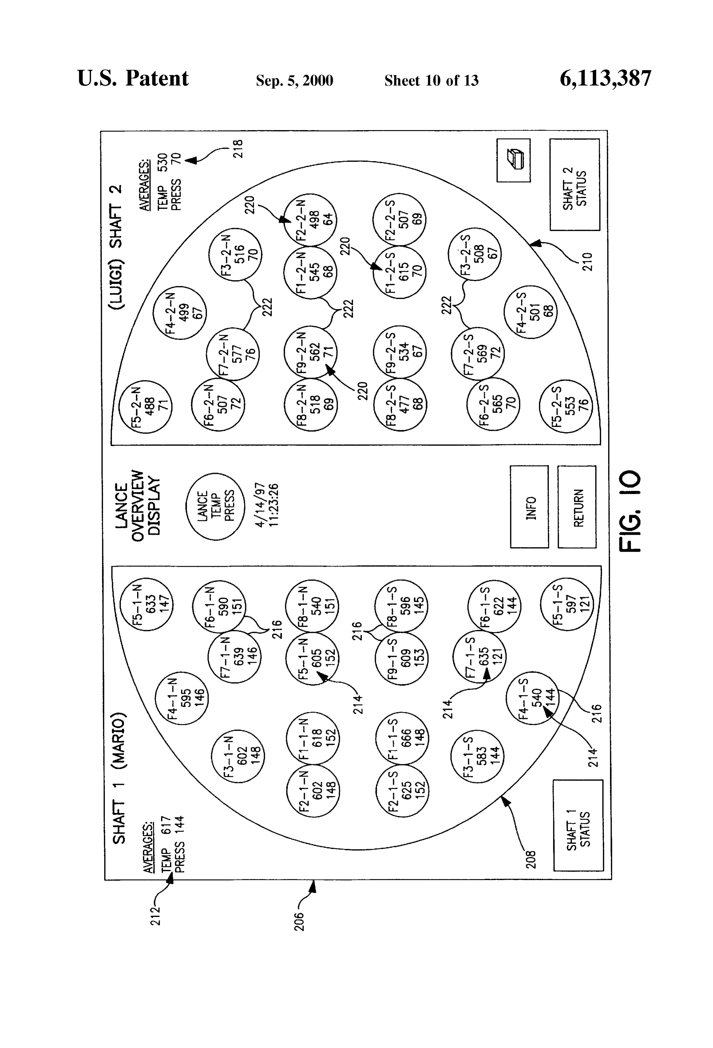
fuel into the fuel lines, it being noted that additional air way of the thermocouples and pressure transducer Systems enters the system 102 via the conduit 100 and fuel and its for each lance in a shaft, as by display indicia 212. In transport air enter the system 102 via the conduit 98. The addition, temperature and pressure information for each valves V1-V9 are preferably rotary valves having an infi lance in the shaft 12 is provided by display indicia 214 nitely variable controller which automatically opens and which preferably includes a representation of the shaft in the closes the valves in accordance with predetermined criteria layout described in connection with FIG. 2, wherein each (i.e. open for 15 minutes, closed for 2 minutes, open for 15 lance is represented by a circle 216. Within each circle 216 minutes, etc.). In the alternative, the automatic sequence of a three-tiered display format is preferably provided which the valves V1-V9 may be overridden in response to a signal includes the lance identification number, the lance from the computer 122. temperature, preferably in degrees Celsius, and the lance Fuel line F4 is shown in greater detail for the purpose of pressure, preferably in millibars. Thus, for lance F4-1-S an example. As can be seen, fuel line F4 splits into line F4-1 which for the purpose of this example has a temperature of and F4-2, wherein F4-1 feeds two lances in one shaft (12) 540 C. and a pressure of 144 millibars, the display circle and F4-2 feeds two lances in the other shaft (14). In this 216 associated therewith preferably has therein the follow regard, a Solenoid actuated valve AV-4 is provided at the 15 ing information for observation by the operator: junction where F4 splits into F4-1 and F4-2, it being understood that similar valves are provided for the other fuel F4-1-S lines. As will be appreciated, the valve AV-4 flip-flops between feeding fuel to F4-1 and F4-2 depending upon 540 which one is active at a given time, it being understood that
F4-1 is active when shaft 12 is active and F4-2 being active 144 when shaft 14 is active. In an alternative embodiment, each valve AV1-AV9 is preferably an electromechanical valve The information can be provided as desired by the opera which may be opened or closed either totally or incremen tor for various periods of time. For example, the operator can tally in response to a signal generated by the computer 122. 25 Select the length of time over which the average indicated by A mechanical splitter valve SV4-2 is provided on F4-2 at the indicia 212 is taken, e.g., 1 minute, 5 minutes, etc., and the junction where F4-2 splits into F4-2-N and F4-2-S, it the information indicated by the indicia 214 may be simi being understood that a similar valve SV4-1 is provided on larly configured. For example, the indicia 214 may represent F4-1, with similarly identified valves provided for the real time readings for each lance or the average for each remaining fuel lines, e.g., SV1-1, SV1-2, SV2-1, SV2-2, etc. lance for a specified period of time, e.g., 1 minute, 5 The splitter valves are operable to divide the fuel flow to minutes, AS will etc.
be noted, the temperature and pressure readings enable the operator to divide the fuel flow between the individual lines as desired, for example to account for circles 222 forastheshown for the lances by indicia 218 and indicia 220 in inactive shaft are significantly lower.
differences in the lengths of the lines, the resistance to flow 35 To alert the operator of progressively increasing tempera caused by bends and the like which create different pressure ture or preSSure of a lance, drops in the lines. In an alternative embodiment, each valve Sively increasing temperatureit and is preferred that the progres SV1-SV9 is preferably an electromechanical valve which played in a flashing format and thenpressure in a readings be dis color-coded format may be manipulated in response to a signal generated by the computer 122. The valves 190 are preferably provided on 40 once the readings exceed predetermined thresholds. For each fuel line downstream of the splitter valve. example, should the logic controller identify that the tem perature is increasing at a rate above a predetermined
Turning to FIG. 9, the connector assembly 118 includes threshold, for example, 25 C. per minute or if an increasing the pressure transducers 198 and a lead 200 electrically temperature is observed over a predetermined interval, Such connecting each transducer 198 to a connector strip 202. The as a continuously increasing temperature for 30 minutes, the transducers convert the preSSure into a low millivolt Signal 45 progressively increasing reading will be displayed as a that is routed via the leads 200 and connector strip 202 to the flashing number. Likewise, if the preSSure reading increases proceSS logic controller 120. The proceSS logic controller above a threshold value or rate, for example 150 millibars, 120 converts the Signal to an output Signal which is routed the display of the numerical representation will be in a to the computer 122 for display on a computer monitor. different color and or provided as a flashing display for The connector assembly 118 also preferably includes a 50 notice by the operator. In addition, the computer may also be connector Strip 204 or routing to the process logic controller programed to generate a signal to Sound an audible alarm or 120 for conversion of the low millivolt electrical output of to generate Signals that are Sent to control equipment, i.e., to the thermocouple to numeric temperature or display on a open or shut or otherwise adjust one or more of the valves computer monitor. to obtain a desired effect.
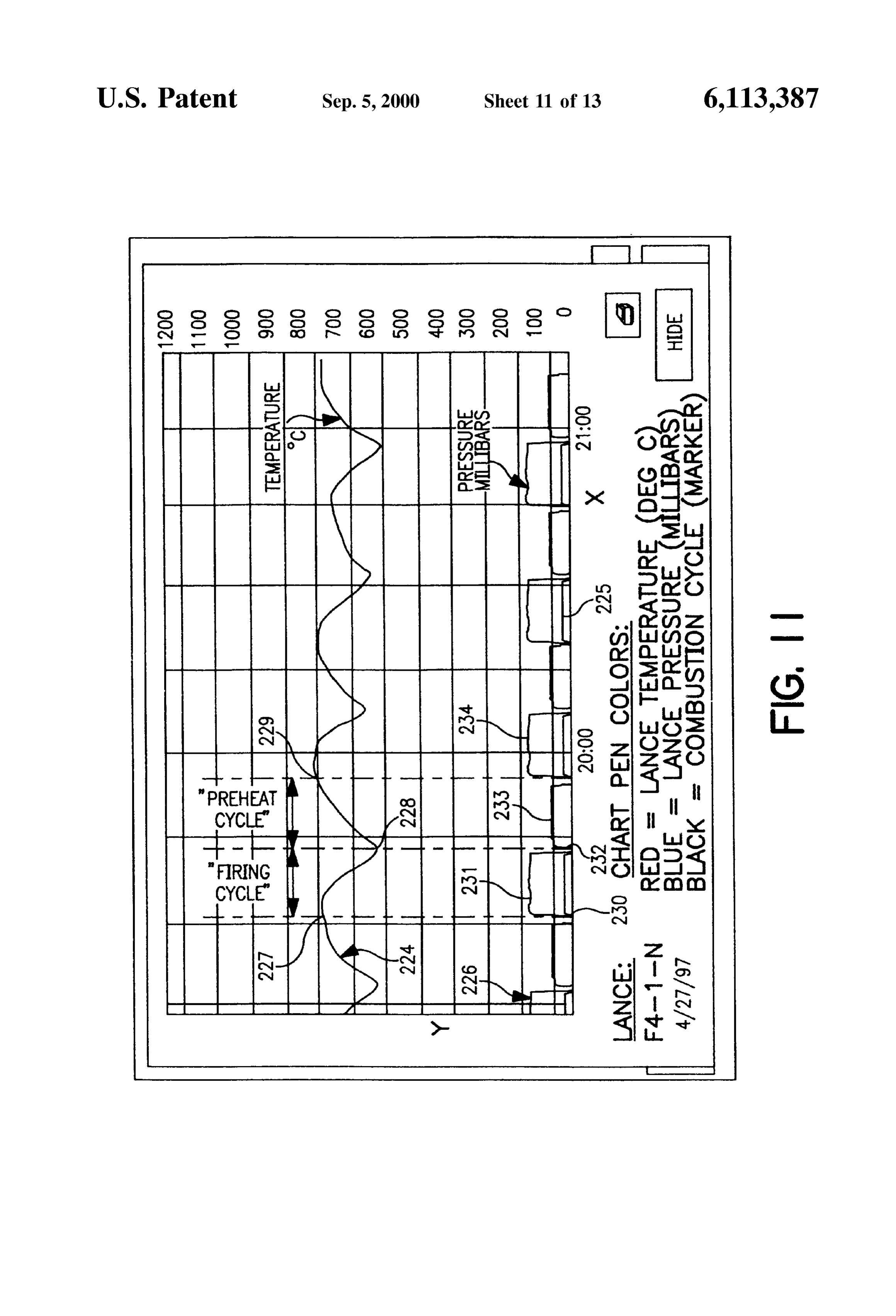
The interface display between the process logic controller 55 In addition to the screen display 216, various other 120 and an operator of the kiln is preferably provided using formats may be provided. For example, FIG. 11 is plot of the computer System 122 operating human-machine inter temperature and pressure for an individual lance versus time face Software available under the trade name InTouch from that is displayed, preferably in response to user input. That Wonderwares Corporation of Irvine, Calif. which displays is, the Y axis is Scaled for reading of millibars and tempera information on a standard computer monitor. FIG. 10 shows 60 ture and the X axis for time. In this plot, the curve 224 a preferred embodiment of one display format for informa represents the temperature readings and the line 226 repre tion in which the screen display 206 provides a shaft Sents the preSSure readings. The combustion cycle is repre representation 208 of the shaft 12 and a shaft representation sented by plot 225 for ease of identification of the beginning 210 of the shaft 14. At this point, shaft 12 is active and shaft and end of the combustion or active cycle. 14 is inactive. 65 FIG. 11 is representative of a properly operating lance, as The representation 208 preferably includes display of the the temperature and pressure are both in the desired range. averages of the temperature and pressure values obtained by That is, for the described kiln operating under conditions
Page 20
selected to provide a rate of production of about 175 metric It has been observed that if the heating problem does not tons/day, the lance temperature is preferably from about cease after numerous cycles (e.g. after about 40 or more), 800° C. to about 500° C. in the active phase and from about there may be a problem in the Shaft commonly referred to as 500° C. to about 800° C. in the inactive phase, and the “hanging characterized by fusing of Stones onto the Shaft pressure is from about 100 millibars to about 200 millibars wall or fusing of numerous Stones into one or more large in the active phase and from about 30 millibars to about 75 blocks, both of which tend to interfere with movement of millibars in the inactive phase. AS will be appreciated, these stone in the shaft. It has been observed that this problem conditions will generally be increased for higher production requires Shutting off fuel to all lances for Several hours until rates and decreased for lower rates. the problem clearS and/or physically removing the fused With further reference to FIG. 11, it has been observed stone from the shaft.
that the lance temperature typically decreases by an amount Accordingly, the operator may manipulate one or more of of from about 100 to about 200 C. during the firing cycle the valves as outlined above to overcome the problem with when coal is injected through the lance, as shown by the the lance. In the alternative, it will be understood that the curve 224 between points 227 and 228. This is believed to computer 122 may compare the measurements of the pres result from the cooling effect of the passage of the relatively 15 Sure and temperature with predetermined criteria and gen cool fuel (typically from about 50° C. to about 70° C.) erate one or more signals to open, Shut or otherwise adjust during injection. Then, during the inactive phase when fuel one or more of the System valves in response to comparison is not injected (between points 228 and 229) the lance of the measured information with predetermined logic cri temperature increases. teria.
Likewise, the lance preSSure as represented by curve 226 In a preferred embodiment, for example, the lance moni Sharply increases at the beginning of the injection of fuel as toring System preferably includes deviation Set points for shown at point 230, levels off to a substantially constant maximum allowable lance temperature and for lance line preSSure throughout the injection or active phase 231 and preSSures which exceed a value in excess of all lances in that sharply decreases back to 0 from about 150 millibars at the shaft. That is, if the average preSSure in all lances is 150 end of the active cycle as shown at point 232. The pressure 25 millibars during firing, an alarm will preferably be set to then rises to a lower pressure during the inactive phase 233 advise of individual lance preSSures which exceed the aver between points 232 and 234. age by about 20 or more millibars (e.g., for pressures above FIG. 12 is an example of a plot such as shown in FIG. 11, about 170 millibars). Thus, as in the case of excessive except the temperature of the lance has exceeded the desired temperatures as described previously, the lance operator will range, as at 235, while the pressure has remained within the shut off fuel to the affected lance or lances in the manner desired range. It has been experienced that a plot Such as described previously until the problem is eliminated. shown in FIG. 12 is typically symptomatic of localized FIG. 13 shows a plot such as FIG. 11 wherein the heating at the lance tip which leads to destruction of the temperature and pressure of a lance have exceeded the lances. desired ranges, as at 236 and 237. It has been experienced In response to an undesirable temperature or preSSure or 35 that this condition typically results from an obstruction at the both for one or more lances, the operator may take various lance tip which plugs the tip, with the plugged condition courses of action in attempt to correct the problem. being particularly identifiable by the pressure Spikes as Likewise, it will be understood that computer logic may also shown at reference numeral 237. It has been experienced be used to evaluate the readings and activate kiln control that lance conditions as represented by this plot and condi equipment, i.e., valves, in the Same manner. 40 tion may also be alleviated in many cases by the Same fuel It has been observed that manifestation of a problem as reduction/shut-off procedure described in connection with shown by the plot of FIG. 12 may be effectively taken care FIG. 12.
of in many instances by decreasing or even Shutting off the For the purpose of further example, it has also been fuel Supply to the affected lance during the Subsequent cycle. observed that a normal lance temperature with a high To accomplish this, an operator may reduce the flow through 45 preSSure is indicative of at least a partial blockage of the fuel or shut off the actuating valve and/or other valves associated line as caused by formation of coke on the interior of the fuel with the affected lance to reduce or even shut off the supply line. This typically must be treated by mechanically remov of fuel through that kiln for a desired period of time, ing the blockage as by use of an auger. Conversely, a high typically ranging from about 1 to 2 cycles, with each cycle temperature and normal preSSure is indicative of uneven being from about 10 to about 20 minutes. 50 Stone movement which is generally treatable by decreasing It has been observed that rapid escalation of lance tem flow to the affected lances as described previously. Thus, peratures such as shown by the plot of FIG. 12 is indicative monitoring both lance temperature and pressure in accor of a heat distribution problem which, if left uncorrected, will dance with the invention is useful to enable more accurate damage the metal of the lance tips. For example, and without diagnosis of the Source of the problem. being bound by theory, it is believed that one cause of 55 Monitoring of the kiln in accordance with the invention localized overheating of a particular lance or lances is has also been observed to be useful to detect problems caused by differential movement of the stone bed wherein during the Start-up phase of the kiln Such as an unsuitable the vertical column of stone within the kiln shaft does not fuel mix or an excess of oxygen in the fuel lines, both of move equally in cross-section while the Shaft is firing. It has which result in excessive lance temperatures or pressures or been observed that the temperature of the affected lances 60 both and if not quickly detected may result in damage to the may be returned to normal by Stopping the fuel Supply to the lances.
affected lances for one or more firing cycles. AS will be appreciated, the present invention enables To accomplish this, the operator shuts off the fuel to the improved control over kiln operation and enables operators affected lances for a cycle and then resumes the Supply of to quickly spot problems which left undetected would likely fuel during the Subsequent cycle. If the heating problem 65 result in damage to the kiln and poor product quality. In reoccurs the operator may repeat the shut off procedure until addition, the kiln and method for operating enable the use of the heating problem ceases. cheaper fuels which in the past have been troubleSome and
Page 21
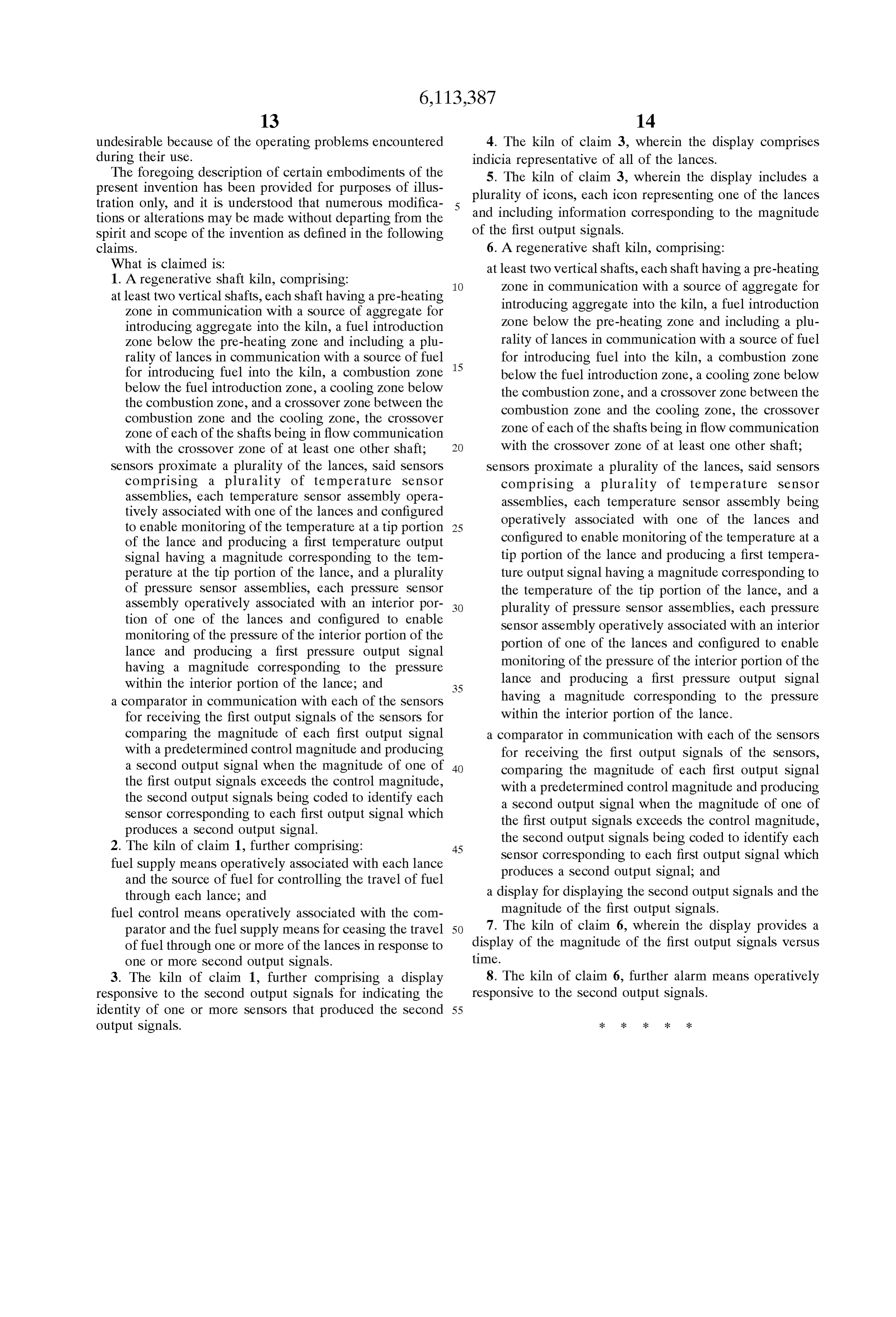
undesirable because of the operating problems encountered 4. The kiln of claim 3, wherein the display comprises during their use. indicia representative of all of the lances. The foregoing description of certain embodiments of the 5. The kiln of claim 3, wherein the display includes a present invention has been provided for purposes of illus plurality of icons, each icon representing one of the lances tration only, and it is understood that numerous modifica and including information corresponding to the magnitude tions or alterations may be made without departing from the
Spirit and Scope of the invention as defined in the following of the first output signals.
claims. 6. A regenerative shaft kiln, comprising: What is claimed is: at least two vertical shafts, each shaft having a pre-heating 1. A regenerative shaft kiln, comprising: Zone in communication with a Source of aggregate for at least two vertical Shafts, each shaft having a pre-heating introducing aggregate into the kiln, a fuel introduction Zone in communication with a Source of aggregate for Zone below the pre-heating Zone and including a plu introducing aggregate into the kiln, a fuel introduction
Zone below the pre-heating Zone and including a plu rality of lances in communication with a Source of fuel rality of lances in communication with a Source of fuel 15 for introducing fuel into the kiln, a combustion Zone for introducing fuel into the kiln, a combustion Zone below the fuel introduction Zone, a cooling Zone below below the fuel introduction Zone, a cooling Zone below the combustion Zone, and a croSSOver Zone between the the combustion Zone, and a croSSOver Zone between the combustion Zone and the cooling Zone, the croSSOver combustion Zone and the cooling Zone, the croSSOver Zone of each of the Shafts being in flow communication Zone of each of the Shafts being in flow communication with the croSSOver Zone of at least one other shaft; with the croSSOver Zone of at least one other shaft; Sensors proximate a plurality of the lances, Said Sensors Sensors proximate a plurality of the lances, Said Sensors comprising a plurality of temperature Sensor comprising a plurality of temperature Sensor assemblies, each temperature Sensor assembly opera assemblies, each temperature Sensor assembly being tively associated with one of the lances and configured operatively associated with one of the lances and to enable monitoring of the temperature at a tip portion 25 of the lance and producing a first temperature output configured to enable monitoring of the temperature at a Signal having a magnitude corresponding to the tem tip portion of the lance and producing a first tempera perature at the tip portion of the lance, and a plurality ture output Signal having a magnitude corresponding to of pressure Sensor assemblies, each preSSure Sensor the temperature of the tip portion of the lance, and a assembly operatively associated with an interior por plurality of pressure Sensor assemblies, each preSSure tion of one of the lances and configured to enable Sensor assembly operatively associated with an interior monitoring of the pressure of the interior portion of the portion of one of the lances and configured to enable lance and producing a first pressure output Signal having a magnitude corresponding to the pressure monitoring of the pressure of the interior portion of the within the interior portion of the lance; and 35 lance and producing a first pressure output Signal a comparator in communication with each of the Sensors having a magnitude corresponding to the pressure for receiving the first output signals of the Sensors for within the interior portion of the lance. comparing the magnitude of each first output Signal a comparator in communication with each of the Sensors with a predetermined control magnitude and producing for receiving the first output signals of the Sensors, a Second output signal when the magnitude of one of 40 comparing the magnitude of each first output Signal the first output Signals exceeds the control magnitude, with a predetermined control magnitude and producing the Second output Signals being coded to identify each a Second output signal when the magnitude of one of Sensor corresponding to each first output Signal which the first output Signals exceeds the control magnitude, produces a Second output signal. the Second output Signals being coded to identify each 2. The kiln of claim 1, further comprising: 45
Sensor corresponding to each first output Signal which fuel Supply means operatively associated with each lance produces a Second output Signal; and and the source of fuel for controlling the travel of fuel through each lance, and a display for displaying the Second output signals and the fuel control means operatively associated with the com magnitude of the first output Signals. parator and the fuel Supply means for ceasing the travel 50 7. The kiln of claim 6, wherein the display provides a of fuel through one or more of the lances in response to display of the magnitude of the first output Signals verSuS one or more Second output Signals. time.
3. The kiln of claim 1, further comprising a display 8. The kiln of claim 6, further alarm means operatively responsive to the Second output signals for indicating the responsive to the Second output signals. identity of one or more Sensors that produced the Second 55 output signals.
Page 22
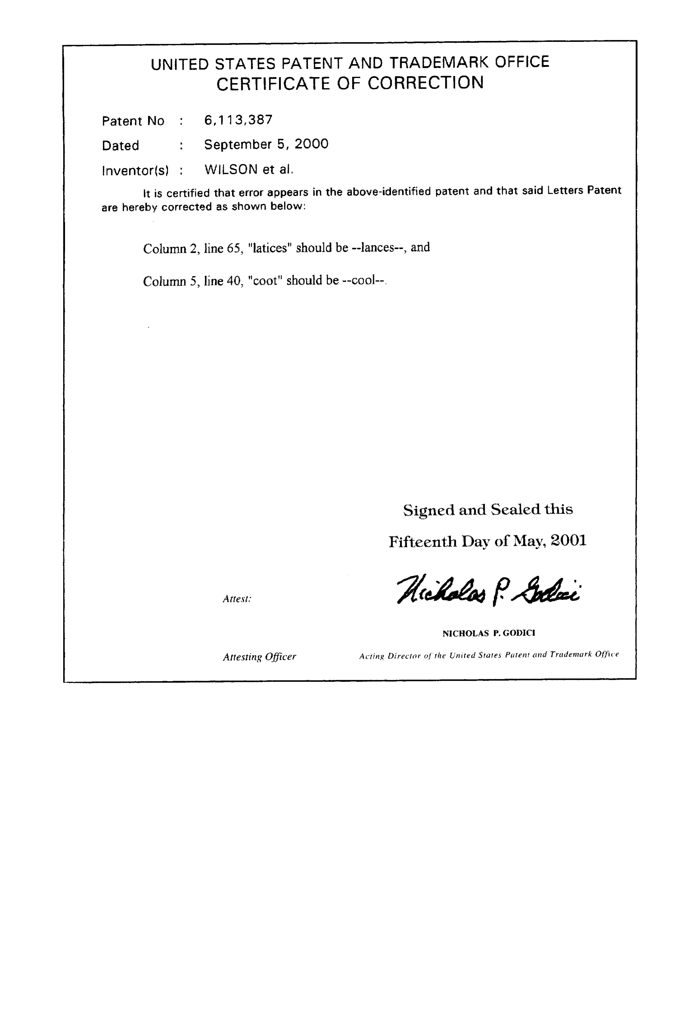
UNITED STATES PATENT AND TRADEMARK OFFICE
CERTIFICATE OF CORRECTION
Inventor(s) ; WILSON et al.,
It is certified that error appears in the above-identified patent and that said Letters Patent are hereby corrected as shown below:
Column 2, line 65, "latices" should be --lances--, and Column 5, line 40, "coot" should be --cool--.
Signed and Sealed this
Fifteenth Day of May, 2001
NCHOLAS P. GOOC
Attesting Officer Acting Director of the United States Patent and Trademark Office
Provenance
- Collection
- Patents citing this work
- Current assignee
- ON Minerals Co
- Original assignee
- Global Stone Corp
- Pages
- 22
- Method
- pdftotext (the PDF's own text layer) + pdftoppm 300dpi page scans
- Patent office record
- patents.google.com →
- Source
- Google Patents citing-documents table
- Inventors
- Herb G. A. Wilson; Jeffery Thompson; Robert Perricone; Michael Barkdoll; Global Stone Corp
- Published
- 2000-09-05
- Transcribed from
- patentimages.storage.googleapis.com →