patent · US4315735
Process for calcining mineral raw materials in a uniflow regenerative shaft furnace
16 February 1982
Page 1 — bibliographic record
United States Patent (19) 11) 4,315,735 Fissl et al. 45) Feb. 16, 1982 54) PROCESS FOR CALCINING MINERAL RAW 3,003,756 10/1961 Steffensen ............................. 432/79 MATER ALS IN A UNIFLOW 3,074,706 1/1963 Schmid et al. . ... 432/99 REGENERATIVE SHAFT FURNACE 3,761,567 9/1973 Parsons .......... ... 423/175 3,771,946 11/1973 Hofer et al. ........................... 432/14 75) Inventors: Erwin Fissl, Zurich; Karl Primary Examiner-Gary P. Straub Scheibenreif, Adliswil, both of Attorney, Agent, or Firm-Toren, McGeady and Stanger
Switzerland 73) Assignee: Maerz Ofenbau AG, Zurich, 57 ABSTRACT Switzerland Either sulphur-containing raw materials or sulphur 21 Appl. No.: 87,308 containing fuels may be used in the calcination of min eral raw materials in a calcining furnace, with signifi 22 Filed: Oct. 22, 1979 cant desulphurization of the calcined material being (30) Foreign Application Priority Data achieved if, on the one hand, cooling air introduced into Dec. 29, 1978 CH Switzerland ....................... 13294/78 the cooling zone of the furnace is removed at the upper end of the cooling zone thereof through exhaust ducts 5) Int. Cl. ........................ C22B 26/20; F27D 3/22; and if, on the other hand, the flue gases are free of F27D 23/00; C01F 11/06 oxygen and have a carbon monoxide content of 1 to 5% 52 U.S. Cl. ...................................... 432/25; 423/175; by volume. In order to obtain this composition of the 423/637; 432/79; 432/96 flue gases, the combustion process can either be per 58 Field of Search ............... 423/173, 175, 177,637; formed in the calcining zone of the calcining shaft of the 432/24, 25, 95, 96, 100, 79 furnace with a deficiency of air or a gaseous, liquid or (56) References Cited solid fuel can be supplied by means of fuel tubes located at a transfer duct between the furnace shafts.
2,654,589 10/1953 Somogyi ............................... 432/79 6 Claims, 2 Drawing Figures
Page 2
Drawing sheet — no readable text.
Page 3
zone of each shaft and by conveying the flue gases from
PROCESS FOR CALCINING MINERAL RAW the uniflow shaft to the counterflow shaft with a carbon MATERIALS IN A UNFLOW REGENERATIV monoxide content of 1 to 5% by volume. SHAFT FURNACE It has been suggested, with regard to the calcination BACKGROUND OF THE INVENTION of lime in uniflow regenerative shaft furnaces, to par tially utilize, in the combustion process, the cooling air
The invention relates to a process for calcining min heated during cooling of the calcined lime. In this con eral raw materials, such as limestone, dolomite, or mag nection, reference is made to the magazine "Zement nesite, in a uniflow regenerative shaft furnace having at 10 Kalk-Gips" (cement-lime-gypsum) 1970, No. 6, pages least two shafts which are connected to each other 277-284. However, it has been found that with this through a transfer or annular duct with each shaft being measure, the required carbon monoxide content in the alternately operated as the calcining or uniflow shaft flue gases cannot be achieved.
and as the counterflow shaft, wherein the calcined raw The various features of novelty which characterize material is cooled in cooling zones of both shafts. 15 the invention are pointed out with particularity in the For calcining mineral raw materials, a regenerative claims annexed to and forming a part of this disclosure. process described in U.S. Pat. No. 3,074,706 is known For a better understanding of the invention, its operat which is frequently used for the construction of uni ing advantages and specific objects attained by its use, flow/counterflow shaft furnaces, having at least two reference should be had to the accompanying drawings shafts. This type of furnace is simple in its operation 20 and descriptive matter in which there are illustrated and and, aside from a low energy consumption, it has the described preferred embodiments of the invention. significant advantage of providing a good soft burning of the calcined raw material, while also being capable of producing medium and hard burning. . . . . . . . DESCRIPTION OF THE DRAWING A large portion of the material produced in such 25 mannerinvention
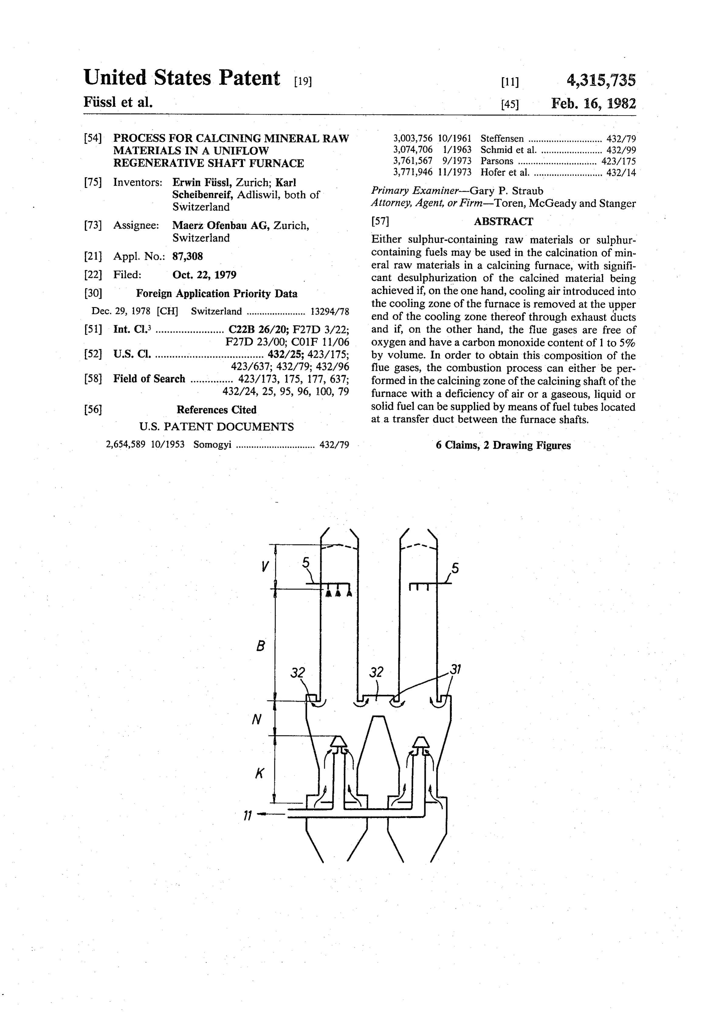
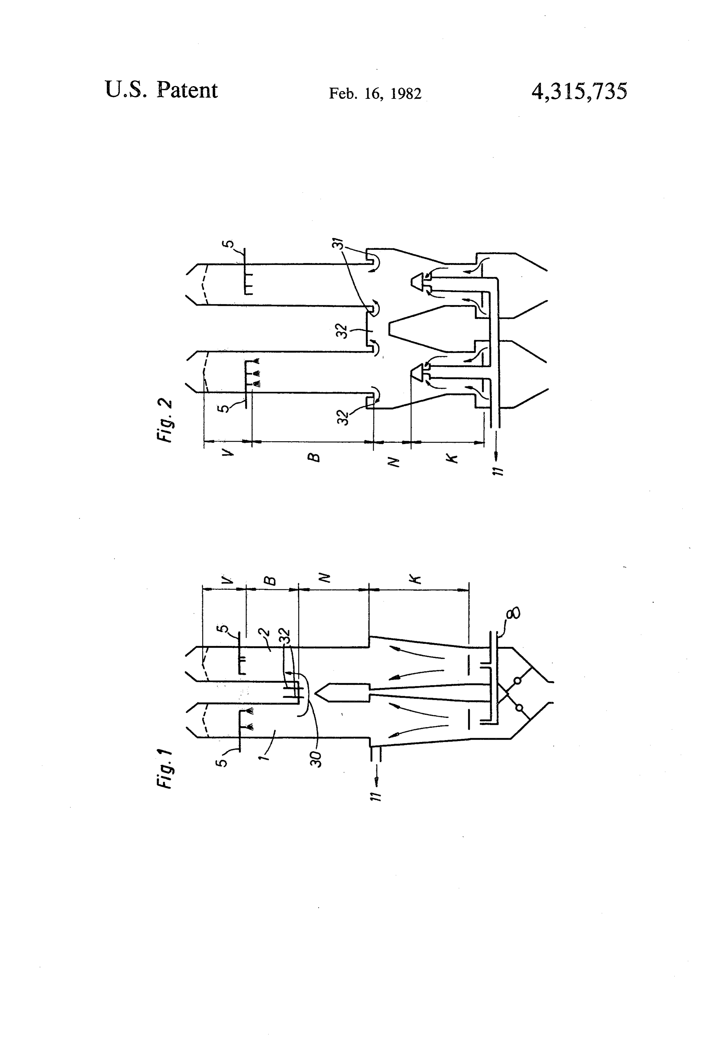
The shall be explained in an exemplified uniflow/counterflow shaft furnaces is utilized in steel furnaces which are ofschematically with the aid two uniflow regenerative shaft illustrated in the mills. For metallic and quality reasons, new and restrict drawing. . .
ing requirements are imposed upon these steel mills. In the drawing: . . . - However, these can only be met when the materials FIG. 1 is a section through a schematically illustrated used in the plants meet certain requirements. Among uniflow regenerative shaft furnace; and . these is the requirement that the lime produced in the 30 FIG. 2 is a section through another schematically calcining furnaces have a very high degree of desul phurization, for example, about 90%. illustrated uniflow regenerative shaft furnace. Experiments have shown (Transactions AIME, vol DETAILED DESCRIPTION OF THE ume 254, March 1973, pages 28-33) that it is possible to PREFERRED EMBODIMENTS achieve a desulphurization of sulphur-containing lime 35 stone or to prevent an absorption of sulphur introduced The shaft furnaces, which are schematically illus with the fuel in the calcined lime, if a reducing atmo trated in FIGS. 1 and 2 have two shafts 1, 2. In the sphere can be adjusted in the calcining zone of the fur embodiment according to FIG. 1, these two shafts 1, 2 nace or in the calcining unit. For a given composition of are connected to each other by means of a transfer duct the flue gases, in accordance with the thermal dynamic 40 30 arranged at the end of a calcining zone B. In the basic equations, the degree of desulphurization in embodiment according to FIG. 2, on the other hand, creases with increasing temperature in dependence the calcining shafts 1, 2 are connected to each other by upon the maximum partial pressure of the SO2 gener means of annular ducts 31.
ated in the flue gases during the desulphurization. The calcining zone B is followed by an after If this finding is to be utilized in the aforementioned 45 deacidification Zone N and, subsequently, by a cooling uniflow/counterflow lime shaft furnace, it would be zone K. Above the calcining zone B, there is addition possible to adjust a reducing atmosphere in the calcin ally provided a preheating zone V. Burners 5 are ar ing shaft of such a furnace by means of combustion with ranged between the preheating zone V and the calcin less than stoichiometric amounts. However, due to the ing zone B.
fact that the cooling air is mixed with the flue gases 50 A reducing atmosphere will be created if, for exam coming from the calcining shaft and with CO2 expelled ple, the shaft 1 is used as the uniflow or calcining shaft from the limestone in the calcining shaft, an oxygen and if the burners 5 are operated with a deficiency of containing atmosphere is obtained in the counterflow air. Simultaneously, the cooling air entering at the shaft. As a result of the equilibrium, this oxygen-con lower end of the cooling zone K through a line 8 is taining atmosphere may again lead to a partial sulphuri 55 either entirely or partially removed at the upper end of zation of the calcined lime. Accordingly, it is not al the cooling zone K through exhaust ducts 11, so that ways possible to achieve the desired high degree of flue gases flowing into the counter shaft are either to desulphurization. tally devoid of, or only insignificantly enriched with, The present invention proceeds from this state of the oxygen from the cooling air.
art and is directed toward development of a process of 60 In the shaft furnace according to FIG. 2, the flue the type described above in such a manner that the flue gases generated in the calcining shaft 1 flow into the gases generated in the uniflow or calcining shaft can be counterflow shaft 2 through the annular ducts 31, with conveyed to the counterflow shaft without oxygen. the cooling air entering the cooling zone K from below SUMMARY OF THE INVENTION and being removed either entirely or partially through 65 exhaust ducts 11, in a similar manner as in the arrange
In accordance with the invention, the desired results ment according to FIG. 1.
are achieved by at least partially removing from the In order to safely obtain a high degree of desulphuri furnace the heated cooling air at the end of the cooling zation in the operation of the furnace, it is essential, on
Page 4
the one hand, that the supply of oxygen into the coun counterflow shaft, said shafts extending in a generally terflow shaft be prevented and that, on the other hand, juxtaposed vertical orientation each defining a bottom the combustion be carried out with a deficiency of air, with a cooling zone proximate said bottom wherein so that oxygen-free gases will be produced which have simultaneous cooling of calcined lime with cooling air is a carbon monoxide content of 1 to 5% by volume. effected in said cooling zones of said shafts, said furnace The aforementioned flue gas composition can also be including transfer duct means located above said cool obtained with a normal combustion of the fuel in the ing zones connecting said shafts in flow communication calcinating shaft by supplying a gaseous liquid or solid with each other, the improvement comprising that cool fuel in the transfer duct 30 between the shaft 1, 2 or in ing air the annular duct 31 at the end of the calcining zone of 10 both saidis shafts introduced simultaneously at the bottom of into said cooling zone, that heated cool the uniflow shaft, by means of one or more fuel tubes 32. ing air is removed at the upper termination of said cool As a result, the oxygen which may possibly be con tained in the flue gases is (chemically) limited and the ing zones from both shafts, that flue gases are conveyed from the one of said shafts operating as a calcining shaft flue gases will contain carbon dioxide and nitrogen and to 1 to 5% by volume carbon monoxide. This flue gas 15 shaftthethrough other of said shafts operating as a counterflow composition is prerequisite for preventing the sulphuri composition ofsaid transfer duct means, and that the the fiue gases conveyed through said zation of the raw materials which are present in the transfer duct means and the amount of cooling air re counterflow shaft 2.
In addition to the combustion reaction of the raw moved from said cooling zones is such that a net reduc materials, the process described also makes it possible to 20 ing atmosphere is maintained throughout the counter safely prevent a sulphurization of the raw materials. flow shaft above the cooling zone.
This does not have a significant negative influence on 2. The improvement according to claim 1 wherein the operation of the shaft furnace and, therefore, the said conveyed flue gases are produced in said calcining advantages of the shaft furnace are preserved, the im shaft by adjusting the combustion conditions therein to portant consideration being that sulphur-containing raw 25 maintain less than stoichiometric proportions. materials and/or sulphur-containing fuels can be uti 3. The improvement according to claim 1 wherein lized and that essentially desulphurized final products said conveyed flue gases are produced by burning fuel can nevertheless be obtained. within said transfer duct means. While specific embodiments of the invention have 4. The improvement according to claim 3, wherein been shown and described in detail to illustrate the 30 one of gaseous, liquid and solid fuel is supplied for the application of the inventive principles, it will be under combustion in said transfer duct means. stood that the invention may be embodied otherwise 5. The improvement according to claim 1 wherein without departing from such principles. said transfer duct means comprise annular ducts. What is claimed is: 6. The improvement according to claim 1 wherein 1. In a process for calcining raw materials, such as 35 the carbon monoxide content of said conveyed flue limestone, dolomite or magnesite, in a uniflow regenera gases is maintained between about 1 to 5 percent by tive shaft furnace having at least two shafts alternately volume.
operated one as a calcining shaft and the other as a sk st x x sk
Provenance
- Collection
- Cited prior art
- Original PDF
- patentimages.storage.googleapis.com →
- Filed
- 1979-10-22
- Pages
- 4
- Method
- pdftotext (the PDF's own text layer) + pdftoppm 300dpi page scans
- Source
- Google Patents bibliographic record
- Granted
- 1982-02-16
- Inventors
- Erwin Fussl; Karl Scheibenreif; Maerz Ofenbau AG
- Transcribed from
- patentimages.storage.googleapis.com →