patent · US4094629
Vertical kiln apparatus
13 June 1978
Page 1 — bibliographic record
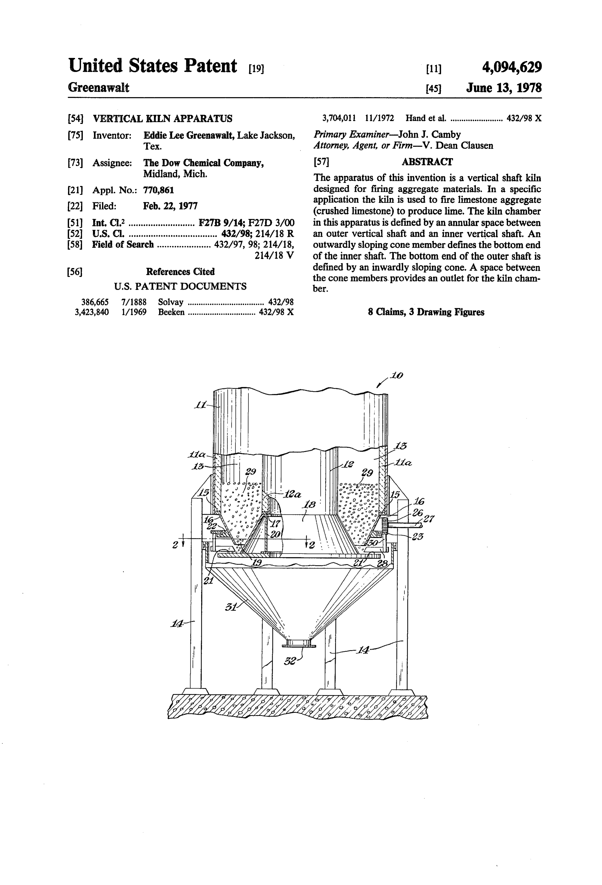
United States Patent 19 (11) 4,094,629 Greenawalt 45 June 13, 1978 54 VERTICAL, KILNAPPARATUS 3,704,011 11/1972 Hand et al. ........................ 432/98 X (75) Inventor: Eddie Lee Greenawalt, Lake Jackson, Primary Examiner-John J. Camby Tex. Attorney, Agent, or Firm-V. Dean Clausen 73 Assignee: The Dow Chemical Company, 57 ABSTRACT Midland, Mich. The apparatus of this invention is a vertical shaft kiln (21) Appl. No.: 770,861 designed for firing aggregate materials. In a specific 22 Filed: Feb. 22, 1977 application the kiln is used to fire limestone aggregate (crushed limestone) to produce lime. The kiln chamber (51) Int, C.’........................... F27B 9/14; F27D 3/00 in this apparatus is defined by an annular space between (52) U.S. C. .................................... 432/98; 214/18 R an outer vertical shaft and an inner vertical shaft. An 58 Field of Search ...................... 432/97, 98; 214/18, outwardly sloping cone member defines the bottom end 214/18 V of the inner shaft. The bottom end of the outer shaft is 56 References Cited defined by an inwardly sloping cone. A space between the cone members, provides an outlet for the kiln cham
386,665 7/1888 Solvay ................................... 432/98 3,423,840 1/1969 Beeken ............................... 432/98 X 8 Claims, 3 Drawing Figures
Page 2
Drawing sheet — no readable text.
Page 3
Drawing sheet — no readable text.
Page 4
Drawing sheet — no readable text.
Page 5
of the wall of the smaller shaft. The wall of the outer
WERTICAL KELNAPPARATUS cone member is sloped inwardly and downwardly from In a typical operation the rock aggregate moves its top end, which is joined to the bottom end of the wall downwardly in the annular chamber through a firing defining the larger diameter shaft. An outlet for the kiln Zone. From the chamber the rock falls through the 5 chamber is provided by a space between the bottom end outlet space and collects on a stationary shelf. As the of the outer cone wall and the outside surface of the rock collects on the shelf it assumes a normal angle of inner cone wall. A flat plate is fastened along its upper repose. The "toe" of the rock is then continuously dis surface to the bottom end of the inner cone wall. The placed by several moving scraper blades. This changes upper surface of this plate extends beyond the inner the normal angle of repose to a steeper angle which O cone wall to provide a shelf. The shelf is designed to allows the rock to slide off the shelf at a controlled, support the aggregate material during downward uniform flow rate. The displaced rock is swept into a movement of the aggregate from the kiln chamber. hopper and falls onto a transport device, such as a con Above the shelf member is a driven gear which is veyor belt, which delivers it to the next point. supported by a support member fastened to the wall of 15 the outer cone. The drive gear is engaged by a driver
BACKGROUND OF THE INVENTION
gear which, in turn, is operatively connected to a drive
This invention relates to an improvement in a vertical means, Several blade members are fastened to the kiln apparatus. In this apparatus an aggregate material, driven gear such that each blade is positioned above the after being fired in the kiln chamber, flows downwardly shelf. During operation of the kiln the blades more in onto a shelf below the chamber. The aggregate is con 20 the same direction as the driven gear and continuously tinuously displaced from the shelf, in volumetrically scrape the aggregate material from the shelf. The dis equal increments, to induce uniform gravity flow of the placed material falls into a collection means positioned aggregate through the kiln. . below the shelf.
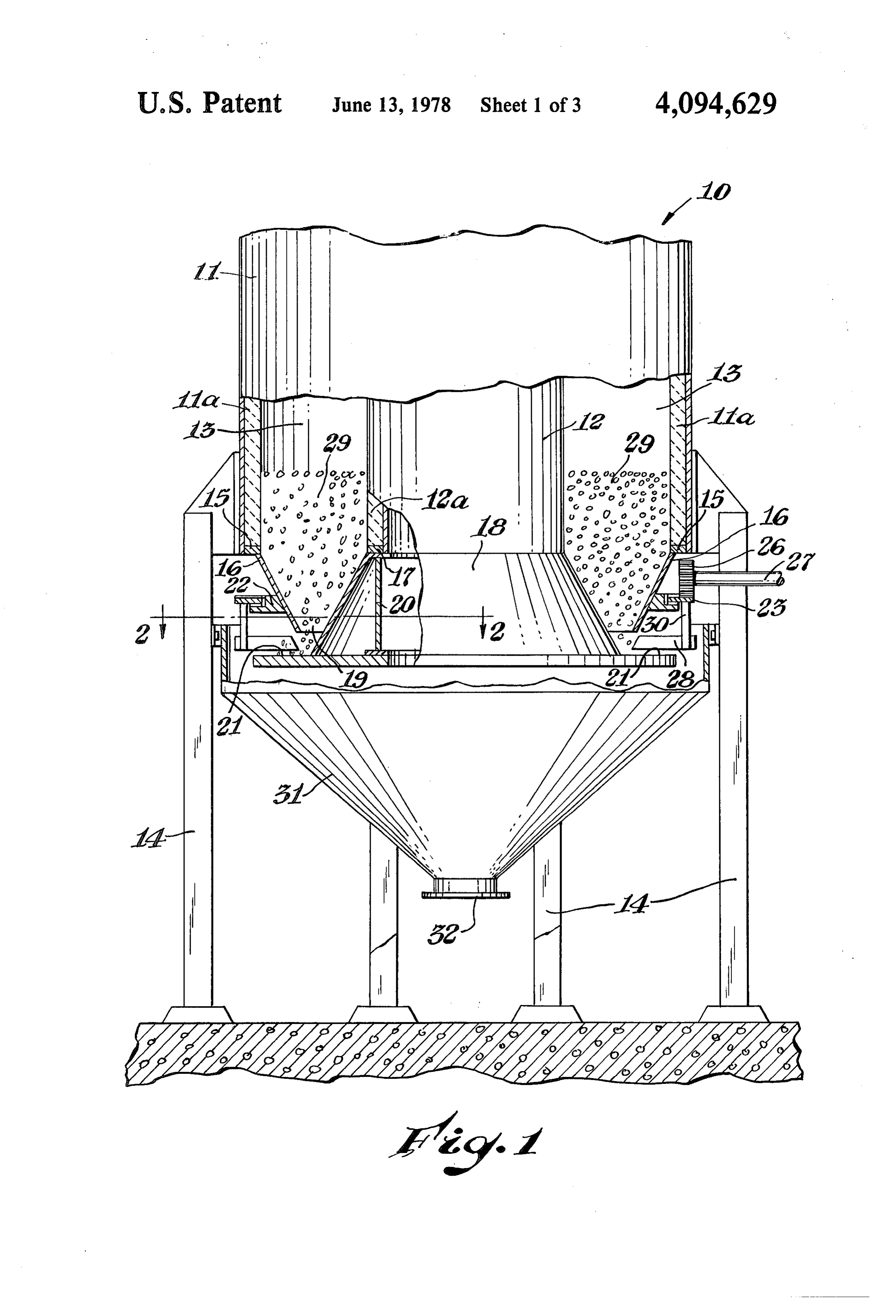
Vertical kilns are used for various applications, such as firing of limestone aggregate to produce lime. A 25 DESCRIPTION OF THE DRAWINGS typical commercially available vertical kiln is a struc FIG. 1 is a side elevation view, partly in section, of ture having a vertical cylindrical shaft which provides a one embodiment of a vertical kiln apparatus according kiln chamber. Pipes which include flame nozzles are to this invention.
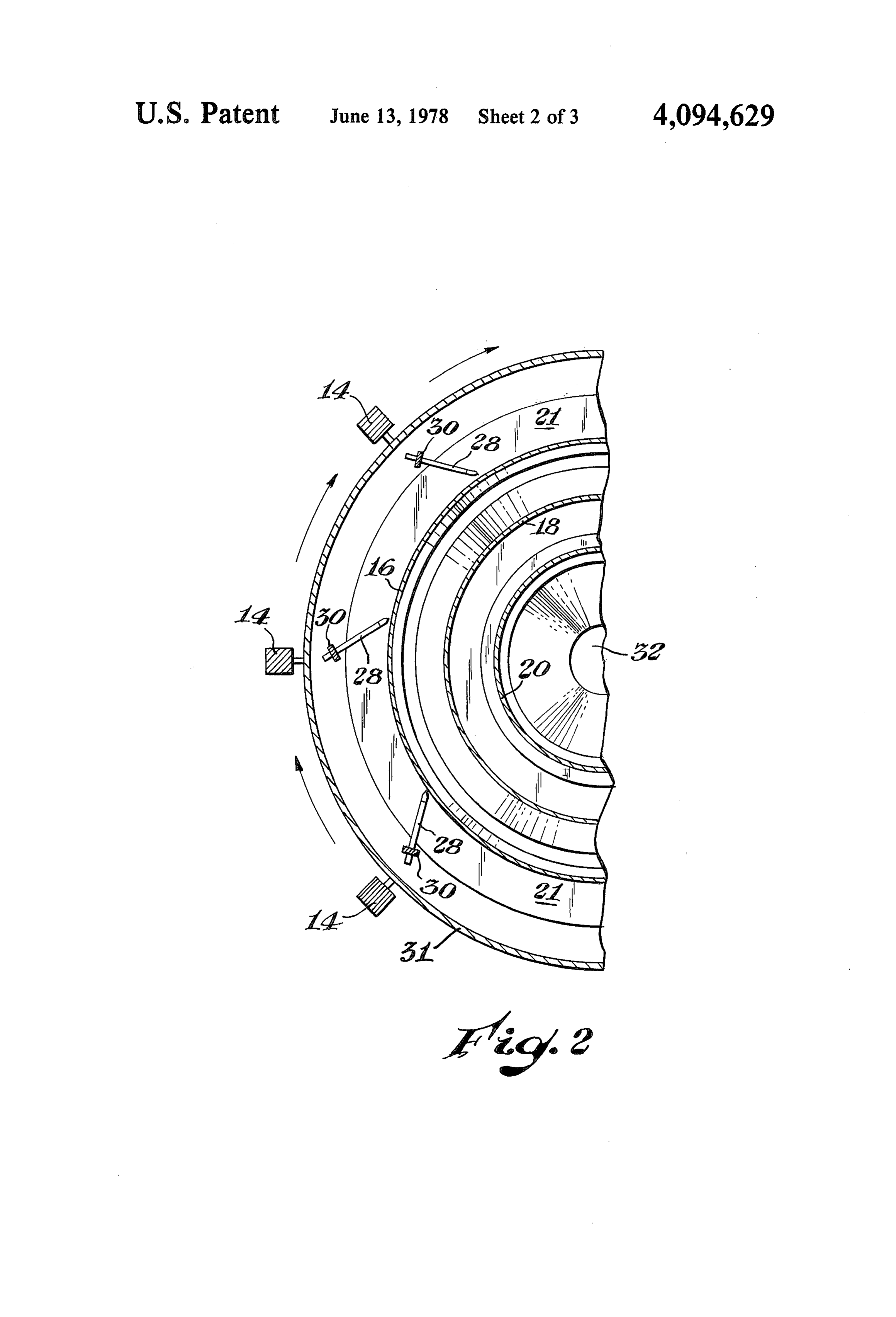
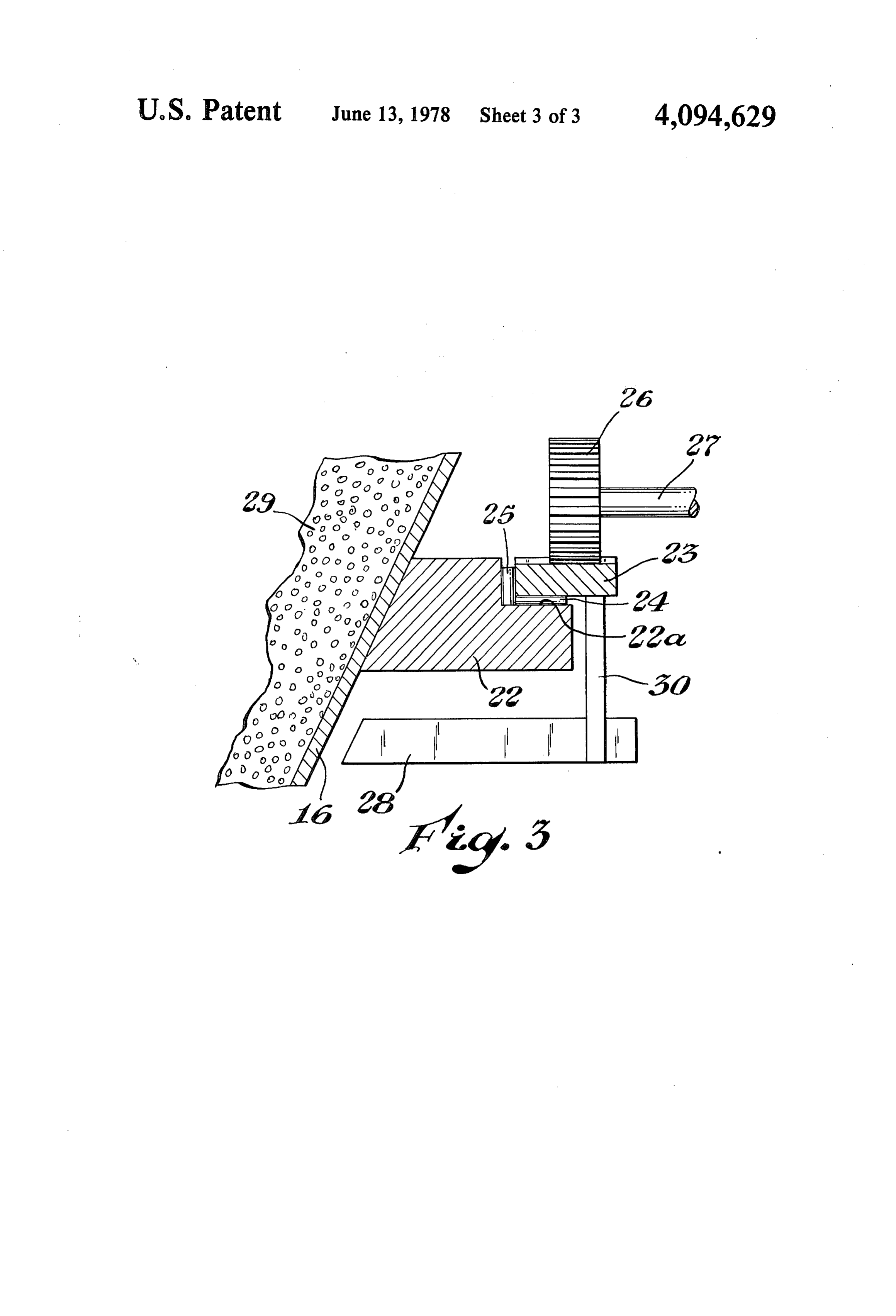
positioned crosswise in the kiln chamber to provide a FIG. 2 is a cross section view, taken along line 2-2, firing zone. These pipe structures are usually referred to 30 of the kiln apparatus of FIG. 1. as firing beams. FIG. 3 is an enlarged detail view illustrating a scraper In the kiln structure described above the firing beams blade component of the kiln apparatus of FIG. 1. cause a problem which is difficult to overcome. For DESCRIPTION OF A PREFERRED example, in the manufacture of lime in a vertical kiln the EMBODIMENT limestone aggregate (crushed limestone) is introduced 35 through the top of the kiln chamber. As the stone falls In the drawing, referring particularly to FIG. 1, the downwardly in the kiln chamber it passes first through numeral 10 generally designates the kiln apparatus of a preheat zone, then through a firing zone, and into a this invention. The basic kiln apparatus is made up of cooling zone at the bottom of the kiln. The firing zone two upright cylindrical shafts 11 and 12. Only the lower is the middle part of the kiln chamber in which the 40 part of each shaft is shown in the drawing. Shaft 11 is an crosswise firing beams are positioned. The presence of outer shaft, of a larger diameter, which encloses the the firing beams disrupts the normal flow of the aggre smaller diameter shaft 12. The inner wall surface of gate, thus causing the aggregate to move at an erratic shaft 11 is lined with a layer 11a of a refractory material. rate through the firing zone. The result of this erratic The outer wall surface of shaft 12 is covered with an flow rate is a variance in the residence time of the ag 45 identical layer of refractory material, indicated by nu gregate in the firing zone, so that inevitably some of the meral 12a. An annular space defined between the re stone is overburned and some is underburned. It fol fractory layers 11a and 12a provides a kiln chamber 13. lows, therefore, that to produce a uniformly, high qual The kiln apparatus 10 is supported by several leg ity aggregate in a shaft kiln, it is essential that the aggre members 14. At the top end each leg is fastened into a gate flow at a controlled, uniform rate through the 50 bracket attached to the outer wall surface of shaft 11. At firing zone. the bottom end of shaft 11 the inner wall surface of the SUMMARY OF THE INVENTION shaft is adhered to a circular ring member 15. An outer cone member 16 is fastened to the bottom end of shaft
The invention is directed to a vertical kiln apparatus 11. More specifically, the wall which defines cone mem useful for firing an aggregate material. The basic appa 55 ber 16 is joined at its top end to the underside of ring ratus is made up of two upright cylindrical shafts, one member 15. The wall of cone member 16 slopes in shaft being of larger diameter than the other. Each shaft wardly and downwardly from its top end. At the bot defines a wall which has a bottom end. The larger diam tom end of shaft 12 a smaller diameter circular ring eter shaft encloses the smaller diameter shaft, in a con member 17 is fastened to the outer wall surface. An centric relationship, The wall of the larger shaft is 60 inner cone member 18 is defined by a wall which is spaced from the wall of the smaller shaft to provide an joined at the top end to the underside of the ring mem. annular kiln chamber between the shaft walls. The an ber 17. The wall of cone member 18 slopes outwardly nular chamber is adapted to receive and contain an and downwardly from its top end.
aggregate material during operation of the kiln. The bottom end of the wall which defines cone mem The apparatus includes two cone members, an inner ber 16 is spaced from the wall of cone member 18. This cone and an outer cone. The wall of the inner cone space, as indicated by numeral 19, is an outlet for the slopes outwardly and downwardly from its top end. kiln chamber 13. A flat circular plate is joined along its The inner cone is joined at its top end to the bottom end upper surface to the bottom edge of the wall which
Page 6
forms the inner cone member 18. This plate is further kiln makes it possible to achieve the desired uniform supported by a vertical ring member 20, which fits flow of aggregate. For example, the annular cross Sec between the underside of ring member 17 and the upper tion of kiln chamber 13 provides a relatively narrow surface of the flat plate. As indicated in the drawing, the space through which the aggregate must move. upper surface of the plate extends beyond the bottom 5 In this narrow chamber the effects of "wall friction' outer edge of the wall which forms the inner cone 18. on the downwardly moving aggregate are substantially This extended portion of the plate upper surface pro equal at all points in the aggregate mass. The narrow vides a shelf 21. The surface which forms shelf 21 is best cross section of the kiln chamber also makes it possible illustrated in FIG. 2. to eliminate the firing beams which are required in the Referring particularly to FIG. 3, a circular support 10 prior vertical kilns. Instead of firing beams the firing member 22 is fastened to the outer surface of the wall of zone in the present kiln apparatus consists of opposing cone 16 at a point above the bottom edge of the cone sets of firing nozzles. One set of nozzles is inset into the wall. A shoulder portion 22a is defined at the top edge refractory layer 11a. An identical set of nozzles is in of support member 22. This shoulder portion is de stalled in refractory layer 12a directly opposite to the signed to support a ring gear 23. It is preferred to sup 15 first set. These firing nozzles, which are located about port the gear 23 on a bearing surface as the gear rides the mid point of the kiln chamber, are not illustrated in around the shoulder 22a. A horizontal bearing surface is the drawing.
provided by a set of roller bearings 24. The vertical There are several other features of the present kiln bearing surface is provided by another set of roller apparatus which enable a uniform flow of the aggregate bearings 25. 20 rock through the kiln chamber. For example, the "toe' The driven gear 23 is rotated by a driver gear 26, of the aggregate 29 can be generally defined as the which is mounted on one end of a shaft 27. The opposite portion of the aggregate material which lies below the end of shaft 27 is connected into a suitable drive means, bottom edge of cone wall 16 and which is at rest on such as an electric motor (not shown). During operation shelf 21. While it is in the rest position the aggregate toe of the kiln 10, the aggregate material 29 in the kiln will 25 portion assumes a normal angle of repose, probably collect on shelf 21. Several upright scraper blades 28 about 45'. At the normal angle of repose the aggregate provide a means for removing the aggregate material material will lie at rest without sliding. However, as from shelf 21. Each scraper blade 28 is secured to the each moving scraper blade 28 displaces a given portion underside of the ring gear 23 by a leg member 30. The of the aggregate toe, the normal angle of repose will size, shape, and sweep angle of each blade is identical, 30 change.
and the blades are connected at equidistant points When the angle of repose changes, the rock above around the ring gear, as best illustrated in FIG. 2. The each moving blade will immediately assume a steeper invention is not limited to the precise structure of the angle. The steeper angle causes the aggregate to slide scraper blades illustrated and described herein. Any downwardly. After each blade passes, the aggregate means may be used which will remove the aggregate 29 35 behind the blade will settle by gravity and again assume from shelf 21 in a manner such that uniform flow of the a normal angle of repose. A good uniform flow of the aggregate through the kiln chamber is achieved. aggregate through the chamber outlet 19 is also made A typical procedure for producing lime in the present possible by the steep downward slope of the inner cone kiln apparatus will now be described to illustrate the wall 18 and the outer cone wall 16. For example, each invention. In this procedure the aggregate material 29 is cone wall has a downward slope of about 30' from crushed limestone rock. At the start of the procedure perpendicular. Since the slope angle of the cone walls is the rock aggregate 29 is loaded into the kiln chamber 13 several degrees steeper than the normal angle of repose, through the top of the kiln apparatus 10. The top of the the aggregate passing downwardly through outlet 19 kiln is not shown in the drawing. The rock aggregate is has a good slide angle at all times. loaded evenly so that the height of the material is the 45 In addition to the advantges described above, the same at all points around the top of the kiln chamber. present kiln apparatus has a capability for using less As the kiln chamber is loaded, the rock aggregate 29 energy than is required by the conventional kilns now in will move downwardly through the outlet 19 and col use. For example, the scraper blades are mounted on lect on shelf 21. After loading is complete the driven ring gear 23 such that each blade sets at an angle. The gear 23 is rotated continuously by the driver gear 27 to 50 blade angle is relative to the perpendicular axis of shelf move the scraper blades 28 in a circular path just above 21 and is toward the direction in which the blade travels the shelf 21. The rate of rotation is variable, at the above the shelf. The preferred set angle for each blade operator's discretion. The travel path of the scraper is from about 30' to 50.
blades may be clockwise, as indicated by the arrows in By setting the scraper blades at an angle, much less FIG. 2, or it can be counter clockwise. As the moving 55 power is required to push the blades through the aggre blades contact the rock which is resting on shelf 21, gate than would be required if the blade faces were each blade removed an equal portion of the "toe" of the pushing flat against the aggregate material. In addition, rock from the shelf. That portion of the rock which is by setting the scraperblades at an angle, the aggregate displaced is swept into a hopper 31 positioned below ahead of each blade is pushed toward the outer edge of shelf 21. The rock in the hopper falls through the the shelf 21, where it can easily fall into the hopper hopper outlet 32 and onto a conveyor belt or other below the shelf.
suitable means for transporting it to the next point. The The invention claimed is:
conveyor means is not illustrated in the drawing. 1. A vertical kiln apparatus for firing an aggregate In the practice of this invention the objective is to material which comprises:
move the aggregate material through the kiln chamber 65 a first upright cylindrical shaft defining a wall which at a uniform rate. This is done to avoid overburning the has a bottom end;
aggregate as it passes through the firing Zone in the a second upright cylindrical shaft defining a wall chamber. The construction and operation of the present which has a bottom end;
Page 7
the second shaft enclosing the first shaft, with the shelf member in the same direction as the driven second shaft wall being spaced from the first shaft gear to continuously remove the downwardly wall to define an annular kiln chamber between moving aggregate material from the shelf member; said shaft walls; and the kiln chamber being adapted to receive and con- 5 a collection means positioned below the shelf mem tain an aggregate material; ber, said collection means being adapted to collect a first cone member having a wall with a top end and the aggregate material removed from the shelf a bottom end, the first cone wall sloping outwardly member.
and downwardly from the top end, and the first cone wall being joined at its top end to the bottom 10 gate The 2. kiln apparatus of claim 1 wherein the aggre removing means comprises at least one upright end of the first shaft wall; blade member, the blade being connected to one end of a second cone member having a wall with a top end a leg member, the opposite end of the leg being con and a bottom end, the second cone wall sloping nected to the driven gear, and the lower edge of the inwardly and downwardly from the top end, and blade being positioned slightly above the shelf member. the second cone wall being joined at its top end to 15 3. The kiln apparatus of claim 1 in which the aggre the bottom end of the second shaft wall;
the bottom end of the second cone wall being spaced gate removing means comprises several upright blade from the first cone wall to define an outlet for the members, each blade is connected to one end of a leg annular kiln chamber; member, the opposite end of each leg is connected to a plate member fastened along its upper surface to the 20 the driven gear at equidistant points on said gear, and bottom end of the wall of the first cone member, the lower edge of each blade is positioned slightly the upper surface of said plate extending beyond above the shelf member.
the outer edge of the bottom end of said first cone 4. The kiln apparatus of claim 3 in which each blade wall, the extended surface defining a shelf member member is set at an angle of from 30' to 50 from the below the kiln chamber outlet, the shelf member 25 perpendicular axis of the shelf member, the angle of set being adapted to support the aggregate material for each blade being toward the direction in which the during a downward movement of the aggregate blade travels above the shelf member.
material from the kiln chamber, through said out 5. The kiln apparatus of claim 1 in which the plate let, and onto the shelf member; member is a circular plate member. a support member fastened to the wall of the second 30 6. The kiln apparatus of claim 1 in which the wall of cone member, and positioned above the shelf mem the first cone member has a downward slope angle ber; which is at least 30' from perpendicular. a driven gear supported by said support member, and 7. The kiln apparatus of claim 1 in which the wall of positioned above the shelf member; the second cone member has a downward slope angle a driver gear which engages the driven gear; 35 which is at least 30' from perpendicular. a drive means operatively connected to the driver 8. The apparatus of claim 1 in which the aggregate. gear; collection means is a hopper positioned below the shelf a means fastened to the driven gear, positioned above member, the shelf member, and adapted to travel above the
Provenance
- Collection
- Cited prior art
- Original PDF
- patentimages.storage.googleapis.com →
- Filed
- 1977-02-22
- Pages
- 7
- Method
- pdftotext (the PDF's own text layer) + pdftoppm 300dpi page scans
- Source
- Google Patents bibliographic record
- Granted
- 1978-06-13
- Inventors
- Eddie Lee Greenawalt; Dow Chemical Co
- Transcribed from
- patentimages.storage.googleapis.com →